BK Radio KNG Series User manual


Contents - Page i
CONTENTS
SECTION I
GENERAL INFORMATION
1.1 Introduction ...................................................................................................................... 1-1
1.2 Description ....................................................................................................................... 1-1
1.3 Technical Characteristics................................................................................................ 1-1
1.4 Factory Options ............................................................................................................... 1-3
1.5 Accessories ..................................................................................................................... 1-3
1.6 License Requirements .................................................................................................... 1-3
1.7 Radio Controls ................................................................................................................. 1-4
1.8 LCD Display...................................................................................................................... 1-4
Status Indicators .............................................................................................................................1-5
Alphanumeric Label Options............................................................................................................1-6
1.9 Programmable Switches and Buttons ........................................................................... 1-7
Options and Labels..........................................................................................................................1-7
1.10 Service Information ...................................................................................................... 1-8
SECTION II
OPERATION AND PROGRAMMING
2.1 General Information ........................................................................................................ 2-1
2.2 Basic Radio Operation .................................................................................................... 2-2

Contents - Page ii
2.3 Radio Functions and Setup ............................................................................................ 2-3
Radio Controls ...............................................................................................................................2-3
Button Options and Labels ...........................................................................................................2-4
Keypad Menu Operation...............................................................................................................2-4
Channel/Zone Selection Options..................................................................................................2-5
Display Options .............................................................................................................................2-8
Command Zones..........................................................................................................................2-10
Building a Command Zone [CHAN+]..........................................................................................2-10
Editing a Command Zone [CHAN-] ............................................................................................2-10
Code Guard and Network Access Codes .................................................................................. 2-11
Code Guard Receive..................................................................................................................2-11
Code Guard Transmit .................................................................................................................2-11
Analog Squelch Control.............................................................................................................. 2-11
APCO Project 25 Digital Squelch Control................................................................................... 2-11
Mixed Mode ..................................................................................................................................2-12
Mixed Mode Talkback .................................................................................................................2-13
Scan Options................................................................................................................................2-13
Channel Scan [SCAN]................................................................................................................2-13
Channel Scan List [SCN+]..........................................................................................................2-14
Talkback Scan ............................................................................................................................2-14
Vote Scan [Requires Option KZA0581] ......................................................................................2-14
Dual Mode Scan [DSCN]............................................................................................................2-16
Priority Scan [PSCN] ..................................................................................................................2-16
Priority Channel Select [PRI]......................................................................................................2-16
Zone Scan [ZSCN] .....................................................................................................................2-18
Zone Scan List [ZSC+] ...............................................................................................................2-19
Picklist Options............................................................................................................................2-19
TX/RX CxCSS Picklist [TXCG] [RXCG]......................................................................................2-19
TX/RX Network Access Code Picklist [TNAC] [RNAC]...............................................................2-20
Talk Group ID Picklist [TGID]......................................................................................................2-20
Encryption Key Picklist [KEY].....................................................................................................2-21
Keyset Picklist [KSET]................................................................................................................2-21
Unit Call Options..........................................................................................................................2-21
Individual Unit Call [UNIT] ..........................................................................................................2-21
Emergency Signalling .................................................................................................................2-22
Messaging ....................................................................................................................................2-24
Text Messaging [TXT].................................................................................................................2-24
User Status Messaging [STS] ....................................................................................................2-26
Paging and Call Alert...................................................................................................................2-28
Conventional Two-Tone/DTMF/MDC1200 Paging [MUTE] .......................................................2-28
Call Alert Paging [ALRT] ............................................................................................................2-29
Radio Check [RCHK] .................................................................................................................2-30
Radio Inhibit/Unihibit [INH][UNIH]..............................................................................................2-31
Other Radio Functions ................................................................................................................2-32
Backlight [LITE] ..........................................................................................................................2-32
Busy Channel Operation ............................................................................................................2-32
Control Lock [LOCK]...................................................................................................................2-33
Monitor [MON] ............................................................................................................................2-34
Contents

Contents - Page iii
Nuisance Channel [NUIS]...........................................................................................................2-34
Radio Information .......................................................................................................................2-34
Repeater Talkaround [T/A]..........................................................................................................2-35
Squelch Adjust [SQL]..................................................................................................................2-35
Site Display [STDS]....................................................................................................................2-35
Site Lock [STLK].........................................................................................................................2-35
Site Search [STSR] ....................................................................................................................2-36
Surveillance Mode [SUR] ...........................................................................................................2-36
Transmit Digital [TXD/A] .............................................................................................................2-36
Transmit Power [PWR] ...............................................................................................................2-37
2.4 Programming Options .................................................................................................. 2-37
Computer Programming ..........................................................................................................2-37
Keypad Programming .............................................................................................................2-37
Global Settings ......................................................................................................................2-39
System Settings.....................................................................................................................2-39
Zone Settings.........................................................................................................................2-40
Channel Settings ...................................................................................................................2-40
P25 ID Unit Call/Receive List ...................................................................................................2-43
User Selectable Code Guards .................................................................................................2-43
User Selectable Network Access Codes ................................................................................2-44
User Selectable Talkgroup IDs ................................................................................................2-44
Keypad Programming Characters ..........................................................................................2-44
2.5 Radio Cloning................................................................................................................. 2-45
SECTION III
THEORY OF OPERATION
3.1 Introduction ...................................................................................................................... 3-1
3.2 Equipment Description.................................................................................................... 3-1
3.3 Theory of Operation......................................................................................................... 3-1
Contents

Contents - Page iv
SECTION IV
MAINTENANCE
4.1 Introduction ...................................................................................................................... 4-1
4.2 Overhaul ........................................................................................................................... 4-1
4.4 Radio Test Procedures .................................................................................................... 4-2
SECTION V
ILLUSTRATED PARTS LIST
5.1 Introduction ...................................................................................................................... 5-1
5.2 Parts List Description...................................................................................................... 5-1
5.3 Assembly Drawing Symbols ........................................................................................... 5-1
5.4 Interconnect Diagram ..................................................................................................... 5-2
5.5 Final Assembly................................................................................................................. 5-3
Parts List..........................................................................................................................................5-3
Assembly Diagram...........................................................................................................................5-3
5.5 Front Assembly ................................................................................................................ 5-5
Parts List..........................................................................................................................................5-5
Assembly Diagram...........................................................................................................................5-5
5.6 Back Assembly................................................................................................................. 5-7
Parts List..........................................................................................................................................5-7
Assembly Diagram...........................................................................................................................5-7
5.7 Systems Assembly .......................................................................................................... 5-7
Parts List..........................................................................................................................................5-9
Assembly Diagram...........................................................................................................................5-9
Contents

Contents - Page v
5.8 Rx/Tx Assembly ..............................................................................................................5-11
Parts List........................................................................................................................................5-11
Assembly Diagram.........................................................................................................................5-13
5.9 System Board................................................................................................................. 5-17
Parts List........................................................................................................................................5-17
Parts Placement ............................................................................................................................5-33
Schematics ....................................................................................................................................5-35
5.10 P-150 Rx/Tx Board ....................................................................................................... 5-55
Parts List........................................................................................................................................5-55
Parts Placement ............................................................................................................................5-71
Schematics ....................................................................................................................................5-73
5.11 P-400 Rx/Tx Board ....................................................................................................... 5-83
Parts List........................................................................................................................................5-83
Parts Placement ............................................................................................................................5-99
Schematics ..................................................................................................................................5-101
5.15 P-500 Rx/Tx Board ......................................................................................................5-111
Parts List...................................................................................................................................... 5-111
Parts Placement ..........................................................................................................................5-127
Schematics ..................................................................................................................................5-129
5.16 P-800 Rx/Tx Board ..................................................................................................... 5-139
Parts List......................................................................................................................................5-139
Parts Placement ..........................................................................................................................5-157
Schematics ..................................................................................................................................5-159
Contents

Contents

BK Radio Page 1-1
SECTION I
GENERAL INFORMATION
1.1 INTRODUCTION
This manual contains information about the physical, mechanical, and electrical characteristics of the BK
Radio KNG Series APCO Project 25 portable digital radios. KNG Portable radios are available in VHF,
UHF and 800 MHz models.
Models Frequency Range
KNG-P150 136 - 174 MHz
KNG-P400 308 - 470 MHz
KNG-P150 440 - 520 MHz
KNG-P800 763 - 870 MHz
1.2 DESCRIPTION
The KNG is a handheld FM transceiver designed for use in domestic and foreign Land Mobile services.
The radio supports standard analog FM and digital C4FM modulation pursuant to TIA-102.BAAD (Project
25 Common Air Interface Description for Conventional Channels) et al. The radio can be congured for
as many as 2048 channels that can be arranged into channel zones. Each channel species unique
receive and transmit RF frequencies, sub-audible squelch, digital control parameters, etc.
Top panel controls include on/off/volume, channel rotary selector, a concentric two-position switch, an
orange momentary switch, and two toggle switches with dealer programmable function. The side panel
contains a PTT switch, and two programmable push buttons. Connectors are provided via the side
connector for external antenna, speaker, microphone, programming, and options. Some models include
a front panel LCD display for status information, four programmable push buttons, and a keypad for
tailoring radio operation.
1.3 TECHNICAL CHARACTERISTICS
OPERATIONAL FEATURES: Programmable Switches, Per Channel Analog/Digital/Mixed-Mode, RX
and TX Dual Priority Scan, Frequency Display, Transmit Time-Out Timer, User Selectable Scan, Scan
Delay, Busy Channel Indicate / Lockout, Tone Code Guard (CTCSS), DTMF/ANI Encode, Digital Code
Guard (CDCSS), Nuisance Channel Delete, Talkback Scan and User Selectable Code Guard.
CHANNELS WITH VARIABLE ZONE SIZE: ................... 2048
OPERATING VOLTAGE: ................................................. 12 VDC Nominal
PHYSICAL DIMENSIONS: .............................................. Weight: 9 oz. (15 oz. with battery)
Width: 2.5 in. (63.5 millimeters)
Depth: 1.8 in. (45.7 mm.)
Height: 5.5 in. (139.7 mm.)
CHANNEL SPACING: ...................................................... 25/12.5 kHz
CHANNEL INCREMENTS: .............................................. 1.25 kHz
ANTENNA TYPE:............................................................. Helical wound molded rubber ex (standard)
Contents

Page 1-2 Service Manual - KNG Portables
General Information
MAX CURRENT DRAIN:.................................................. Transmit High Power: 1.5 amps
Receive: 255 mA
Standby: 20 mA (battery save on)
Standby: 100 mA (battery save off)
OPERATING TEMPERATURE: ...................................... -30° to +60° C
Receive: 2 A
Standby: 150 mA
OPERATING TEMPERATURE: ...................................... -30° to +60° C
Specication M-150 M-400 M-500 M-800
Frequency Range 136 - 174 MHz 380 - 470 MHz 440 - 520 MHz 763 - 870 MHz
FCC ID
Receiver
Sensitivity: 12db SINAD -121 dBm -119 dBm -121 dBm -119 dBm
P25 Sensitivity: 5% BER -121 dBm -119 dBm -121 dBm -119 dBm
Adjacent Channel Rejection
Per TIA/EIA-603 2.1.6
80 (70) dB 78 (67) dB 79 (67) dB 72 (63) dB
P25 Adjacent Channel Rejection 60 dB 60 dB 60 dB 60 dB
Spurious and Images 80 dB 80 dB 85 dB 75 dB
Intermodulation Rejection 78 dB 75 dB 77 dB 75 dB
Audio Response +1dB / -3dB +1dB / -3dB +1dB / -3dB +1dB / -3dB
Audio Distortion at 5W 2 % 2 % 2 % 2 %
RX Current Draw 2 A 2 A 2 A 2 A
Transmitter
RF Power (Watts) 10-50 or 50-100 10-40 or 40-100 10-40 10-35
Frequency Stability 1.5 ppm 1.5 ppm 1.5 ppm 1.5 ppm
Modulation Deviation 5 (2.5) kHz 5 (2.5) kHz 5 (2.5) kHz 5 (2.5) kHz
Audio Distortion 3 % 3 % 3 % 3 %
FM Hum & Noise 50 (45) dB 50 (45) dB 50 (45) dB 50 (45) dB
Spurious and Harmonics 75 dB 75 dB 75 dB 75 dB
Current Draw @ High Power 15 A @ 50 W
20 A @ 100 W
15 A @ 40 W
20 A @ 100 W
15 A 15 A
Audio Response +1dB / -3dB +1dB / -3dB +1dB / -3dB +1dB / -3dB
Modulation 16K0F3E
(11K0F3E)
8K10F1E
(8K10F1D)
Contents

BK Radio Page 1-3
General Information
1.4 FACTORY OPTIONS
Factory installed options are referenced on the back of the radio.
The following list includes options available at the time of printing.
KZA0558 Intrinsically Safe
KZA0570 Over-the-Air Rekeying (OTAR)
KZA0577 AES and DES Encryption
KZA0579 Project 25 Digital Trunking
KAA0582 Over-the-Air Programming (OTAP)
KZA0583 Vote Scan Operation
1.5 ACCESSORIES
Use only BK Radio approved supplied or replacement antennas, batteries, and accessories. Use of non-
BK Radio approved antennas, batteries, and accessories may exceed the FCC RF exposure guidelines.
For a list of BK Radio approved accessories visit the following web site: http://www.relm.com.
1.6 LICENSE REQUIREMENTS
This equipment must be licensed by the Federal Communications Commission (FCC) before it may be
used. Your BK Radio dealer can assist you in ling the appropriate application with the FCC and program
each radio with your authorized frequencies and signaling codes.
Contents

Page 1-4 Service Manual - KNG Portables
General Information
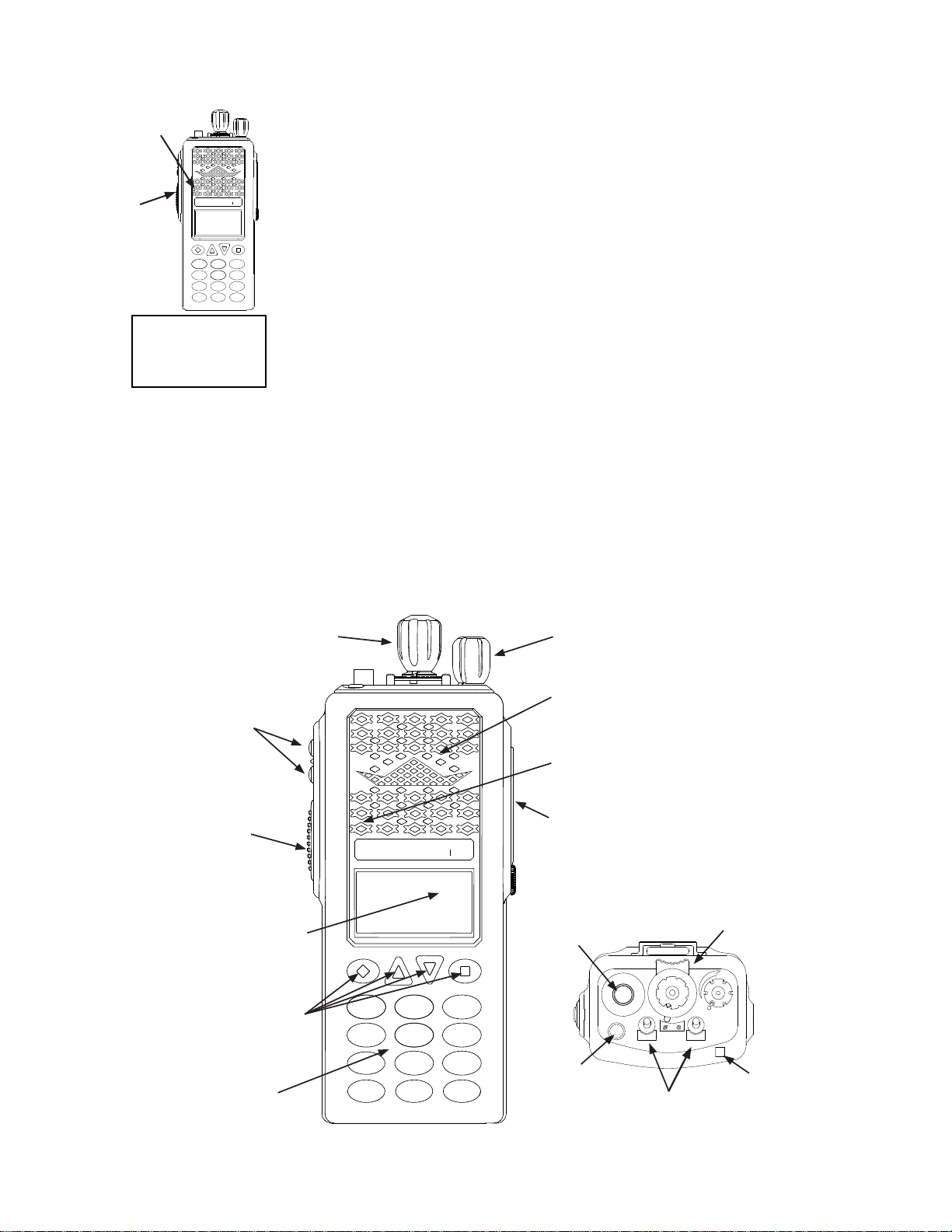
1.7 RADIO CONTROLS
Square Button
KNG
ABC DEF
GHI JKL MNO
PQRS TUV WXYZ
*
#
123
4
789
56
0
BK RADIO
Ch 1
KNG-CMD
171.58500 MHz
CHAN+ TXCG ZONE MENU
Programmable
Side Buttons
Push-to-Talk
Speaker
Accessory Connector
Alphanumeric Display
Microphone
Diamond Button
Up Arrow Button
Down Arrow Button
Keypad
SCAN
PRI
VOL
On/Off Volume
Channel/Zone Select Collar Switch
Antenna Connector
Emergency Button
Toggle Switches
LED Indicator
RXD ØH
C
1.8 LCD DISPLAY
The KNG display can be programmed
for a variety of options and functionality.
Check with your RELM/BK Radio
dealer or communications ofcer
for information on the programmed
functions of your radio.
NOTE: The KNG display can be programmed to display different information when a trunking or
conventional channel is selected.
Ch 1
KNG - P150
171.58500 MHz
CHAN+ TXCG ZONE MENU
RXD
C
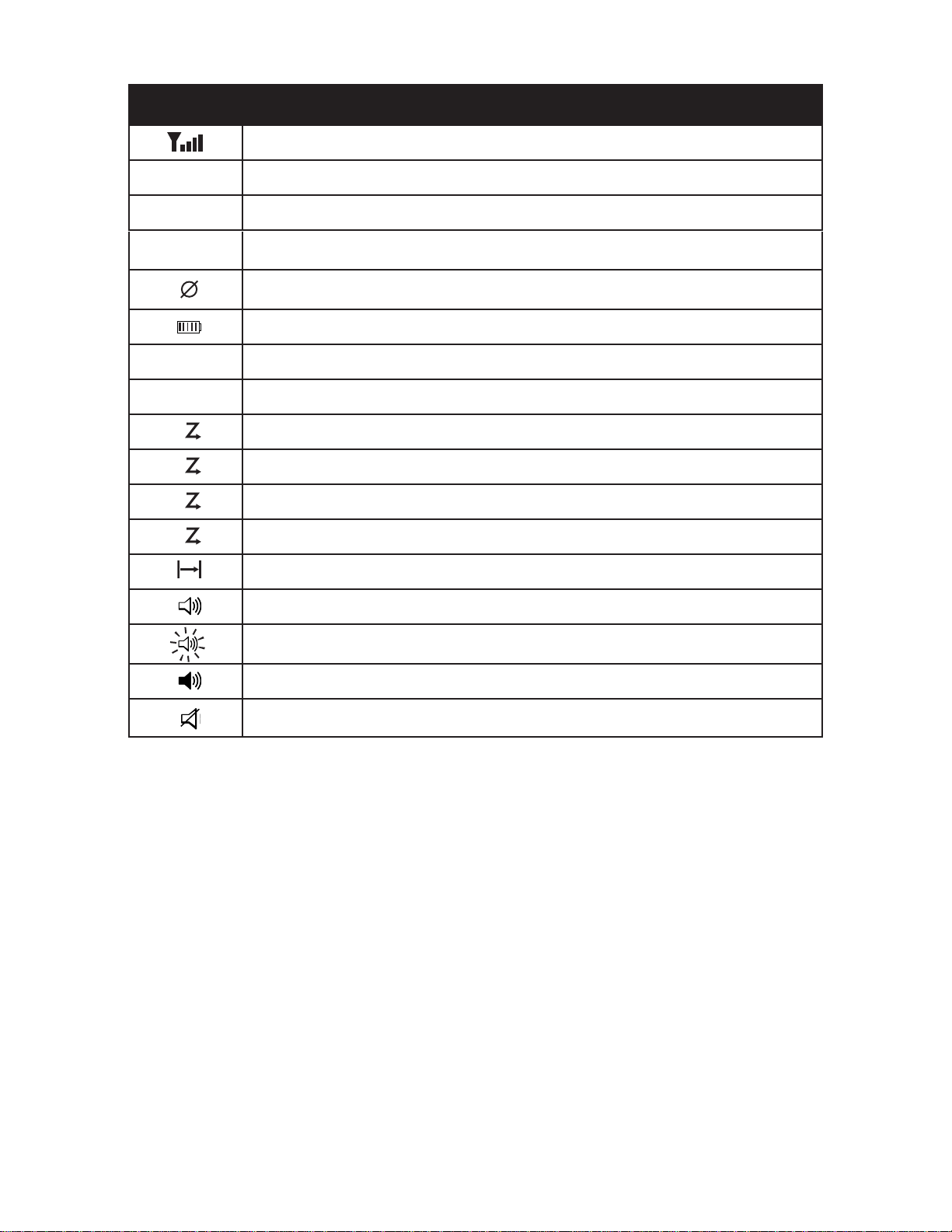
Status Indicators
Programmable Alphanumeric Labels
Programmed Button Labels
Contents
BK Radio Page 1-5
General Information
STATUS INDICATORS
Receiver Signal Strength
RXD, RXA Receive Digital, Receive Analog, Hold Time Active
TXD, TXA Transmit Digital, Transmit Analog
H/L High/Low Transmit Power
Selected channel Tx is encrypted or Rx incoming signal is encrypted
Battery Level Indicator
P1, P2 Priority 1 Channel, Priority 2 Channel
Scanned Channel
C
Channel Scan On
D
Dual Mode Scan On
Z
P
Zone Scan On
C
P
Priority Scan On
Repeater Talkaround Enabled
Monitor Mode
Flashing indicates Normal Mode in digital operation
Open Audio
Voice Mute Enabled
Contents

Page 1-6 Service Manual - KNG Portables
General Information
ALPHANUMERIC LABEL OPTIONS
NOTE: Three channel information lines are programmable with PC Radio Editor.
Channel Number Channel Number of Currently Selected Channel or Active Scanned Channel
Channel Label Alphanumeric Label of Currently Selected Channel or Active Scanned Channel
Channel Number and
Zone Label Currently Selected Channel number and Currently Selected Zone Label
Frequency* Operating Frequency of Currently Selected Channel or Active Scanned Channel
Unit ID Shows your P25 Unit ID
While receiving, the ID of the radio transmitting the message is displayed
If the received ID is programmed in your radio's Call List, the corresponding label will
be displayed
Received Talk Group ID P25 Talk Group ID of the radio transmitting the message currently being received
Pick List Selection* NAC, TGID or Code Guard currently selected from the programmable Pick Lists
Zone Label Label of Currently Selected Zone
Zone # and Channel # Currently Selected Zone and Channel Numbers
Zone Number Currently Selected Zone Number
RX/TX Key Currently selected encryption key
Subaudible* Displays CxCSS value of received signal
DTMF* Displays the numeric DTMF tones of received signal
MDC* Displays the numeric MDC ID of received signal
*Conventional Channels Only
Contents

BK Radio Page 1-7
General Information
1.9 PROGRAMMABLE SWITCHES AND BUTTONS
The KNG portable radio is equipped with seven programmable control buttons and three programmable
switches. Switch and button functions are assigned via PC programming.
NOTE: Switches, buttons and menu items can be programmed for different functions when a trunking or
conventional channel is selected.
The Diamond, Up Arrow, Down Arrow, and Square buttons are programmable with PC Radio Editor
Software. The programmed functions are activated by pressing the associated button. Active functions
are indicated by a highlighted background.
SCN = Active, SCN = Inactive.
SCAN
PRI
VOL
Right ToggleCollar Switch
Left ToggleOrange Button
KNG
ABC DEF
GHI JKL MNO
PQRS TUV WXYZ
*
#
123
4
789
56
0
BK RADIO
Square
Diamond
Up Down
Side Buttons
SCAN
PRI
On Off
On Off
OPTIONS AND LABELS
Menu Switch Button Label Trunk Conv.
Backlight x x x LITE x x
Channel Scan x x x SCAN x
Channel Scan List x x SCN+ x
Channel Select x x CHAN x x
Cloning x-x
Contrast x-x x
Control Lock x LCK x x
Dual Mode Scan x x x DSCN x x
Emergency1x-x x
Menu x MENU x x
Monitor x x x MON x
Nuisance Channel Delete xDEL x
Picklist - Rx CxCSS x x RXCG x
Picklist - Rx NAC x x RXNC x
Picklist - Talkgroup ID x x TGID x
Picklist - Tx CxCSS x x TXCG x
Picklist - Tx NAC x x TXNC x
Picklist-KEY* x x KEY x
Picklist-KEYSET* x x KSET x
(cont.)
Contents

Page 1-8 Service Manual - KNG Portables
General Information
Menu Switch Button Label Trunk Conv.
Priority Channel Select x x PRI x
Priority Scan x x x PSCN x x
Radio Info x -
Rekey Request x x RKEY x x
Repeater Talkaround x x x T/A x
Squelch Adjust x x SQL x
Surveillance Mode x x x SURV x x
System Test x -
Tx Digital/Analog x x x TXAD x
Tx Power x x x PWR x x
Tx Secure x x x SEC x x
Unit Call x x UNIT x x
User Status x x STS x
Version x-
Voice Mute x x MUTE x
Zeroize Keys* x x ZERO x x
Zone Scan x x x ZSCN x
Zone Scan List x x ZSC+ x
Zone Select x x ZONE x x
Call Alert** x x ALRT x
Site Display** x x STDS x
Site Lock** x x STLK x
Site Search** x x STSR x
Emergency button can only be assigned to the orange button.
* Requires Encryption option.
** Trunking Channels Only. Requires P25 Trunking option.
1.10 SERVICE INFORMATION
If you need service, contact your local BK Radio dealer equipped to service your radio. If you nd it
impractical to have service performed by your local dealer, contact BK Radio at the address below:
BK Radio Attention: Customer Service
7100 Technology Drive
West Melbourne, FL 32904
Voice (800) 422-6281
FAX (321) 953-7986
Contents

BK Radio Page 2-1
SECTION II
OPERATION AND PROGRAMMING
2.1 GENERAL INFORMATION
This section contains information concerning the installation and programming of the BK Radio KNG
APCO Project 25 digital radios.
UNPACKING AND INSPECTING EQUIPMENT
Exercise extreme care when unpacking the equipment. Make a visual inspection of the unit for evidence
of damage incurred during shipment. If a claim for damage is to be made, save the shipping container
to substantiate the claim. The claim should be promptly led with the transportation company. It would
be advisable to retain the container and packaging material after all equipment has been removed in the
event that equipment storage or reshipment should become necessary.
BATTERY INSTALLATION
Installing the Battery
1. Turn the radio off.
2. Align the tabs on the bottom of the battery with the slots on the radio.
3. Push the top of the battery toward the radio until release tab “clicks”
into place.
Removing the Battery
+TS ON
-
Release Tab
1. Slide the release tab toward the bottom of the radio.
2. Pull the top of the battery out.
(Approximately 30o)
3. Pull up to remove the battery pack.
NOTE: All information programmed into the radio is maintained even when the battery pack is removed.
BK Radio battery packs are available in a variety of capacities and types for special applications.
Rechargeable battery packs can be charged separately or while attached to a radio.
Periodically check the contacts on the battery pack for dirt that could prevent a good electrical contact
with the charging base.
Contents

Page 2-2 Service Manual - KNG Portables
Operation and Programming
ANTENNA INSTALLATION
NOTE: Transmitting without an antenna could result in damage to your radio.
Use RELM/BK Radio approved antennas only. Use of non-qualied or mismatched antennas could
result in diminished radio operation. Published radio specications cannot be guaranteed with non-
approved antennas. Bent, broken or damaged antennas should be replaced.
INSTALLING THE ANTENNA
Insert the radio’s antenna connector into the threaded connector of the
antenna and turn it clockwise until it is rmly seated.
REMOVING THE ANTENNA
Holding the base, turn the antenna counterclockwise until released.
2.2 BASIC RADIO OPERATION
Turn power on by turning the Volume knob clockwise. A beep sounds, indicating the radio is operational.
The LCD display shows the programmed display information of the currently selected channel.
RECEIVE
15
1
2
3
4
5
6
7
89
1 1
10
12
13
14
16
SCAN
PRI
VOL
Ch 1
KNG - P25
171.58500 MHz
LITE T/A MENU LCK
RXD
Set the volume knob to approximately 50-60%.
When a signal is received, the unprogrammable top line of the display indicates
the signal strength and operating mode of the incoming transmission. RXA =
analog, RXD = digital.
The check radio volume when no signal is being received, put the Monitor mode
in “Open Squelch” (see “Monitor”) and adjust the volume to a comfortable level.
Contents
BK Radio Page 2-3
Operation and Programming
TRANSMIT
Ch 1
KNG - P25
171.58500 MHz
LITE T/A MENU LCK
TXD
KNG
ABC DEF
GHI JKL MNO
PQRS TUV WXYZ
*
#
123
4
789
56
0
BK RADIO
Microphone
PTT
1. Press the PTT (Push-To-Talk) switch. When the radio is transmitting the
indicator LED glows red and TXD or TXA appears in the display.
2. Talk in a normal voice with the microphone one to two inches from your
mouth.
3. Release the PTT switch to stop transmitting.
If the length of your message is nearing the programmed Time-Out Timer
setting, a tone sounds indicating 5 seconds left to transmit. At the end of the
programmed time, the transmitter automatically shuts off and an alert tone
sounds. To continue transmission, release the PTT switch, then press it again
and continue talking.
If the Transmit Indicator does not glow and a tone sounds, you are on a receive-
only channel or the channel is busy (see Busy Channel Lockout). Select an
authorized transmit channel.
NOTE: When using a channel programmed for mixed mode transmit the signal will be transmitted in the
mode selected by the TX Digital selection. Or if programmed for Mixed Mode Talkback, the radio will
transmit in the mode of the last received channel while the “RX” icon is displayed. (See Mixed Mode
Operation.)
2.3 RADIO FUNCTIONS AND SETUP
RADIO CONTROLS
KNG
ABC DEF
GHI JKL MNO
PQRS TUV WXYZ
*
#
123
4
789
56
0
BK RADIO
On/Off
Volume
Programmable
Side Buttons
Push-to-Talk
Speaker
Accessory
Connector
Alphanumeric
Display
Microphone
Programmable
Buttons
Keypad
Channel/Zone
Select
Collar Switch
Antenna
Connector
Emergency
Button
Toggle Switches
LED
15
1
2
3
4
5
6
7
89
1 1
10
12
13
14
16
SCAN
PRI
VOL
Contents

Page 2-4 Service Manual - KNG Portables
Operation and Programming
Button Options and Labels
The Diamond, Up Arrow, Down Arrow, and Square buttons are programmable with PC Radio
Editor Software. The programmed functions are activated by pressing the associated button. Active
functions are indicated by a highlighted background.
SCN = Active, SCN = Inactive.
15
1
2
3
4
5
6
7
89
1 1
10
12
13
14
16
SCAN
PRI
VOL
Right ToggleCollar Switch
Left ToggleOrange Button
KNG
ABC DEF
GHI JKL MNO
PQRS TUV WXYZ
*
#
123
4
789
56
0
BK RADIO
Square
Diamond
Up Down
Side Buttons
15
1
2
3
4
5
6
7
89
11
10
12
13
14
16
SCAN
PRI
On Off
On Off
Keypad Menu Operation
One button can be programmed as “Menu”. Items shown in the Options and Labels table can be
programmed and arranged via PC programming. These items can then be accessed with the Menu
button.
To select from the menu:
Channel Scan
Tx Digital
PRI Scan
ESC ▲ ▼ ENT
TXD
1. Press the programmed “Menu” button.
2. Scroll to the desired menu item with the up/down buttons .
3. Press the button marked ENT to open the item.
Options and Labels
Menu Switch Button Label Trunk Conv.
Backlight xxxLITE x x
Call Alert x x ALRT x x
Channel Add/Delete x CHAN+/- x
Channel Scan x x x SCAN x
Channel Scan List x x SCN+ x
Channel Select x x CHAN x x
Cloning x-x
Contrast x-x x
Control Lock x x x LCK x x
Dual Mode Scan x x x DSCN x x
Emergency1x-x x
Inhibit x x INH x
Menu xMENU x x
Monitor xxxMON x
Nuisance Delete x DEL x
Picklist - Rx CxCSS x x RXCG x
(cont.)
Contents

BK Radio Page 2-5
Operation and Programming
Options and Labels (cont.)
Menu Switch Button Label Trunk Conv.
Picklist - Rx NAC x x RXNC x
Picklist - Talkgroup ID x x TGID x
Picklist - Tx CxCSS x x TXCG x
Picklist - Tx NAC x x TXNC x
Picklist-KEY* x x KEY x
Picklist-KEYSET* x x KSET x x
Priority Channel x x PRI x
Priority Scan x x x PSCN x x
Radio Check x x x RCHK x
Radio Info x -x x
Rekey Request x x RKEY x x
Repeater Talkaround x x x T/A x
Site Display x x STDS x
Site Lock x x STLK x
Site Search x x STSR x
Squelch Adjust x x SQL x
Surveillance Mode x x x SURV x x
System Test x -
Text Message x x TXT x
Tx Digital/Analog x x x TXAD x
Tx Power x x x PWR x x
Tx Secure x x x SEC x x
Unihibit x x UNINH x
Unit Call x x UNIT x x
User Status x x STS x
Version x-x x
Voice Mute x x MUTE x
Zeroize Keys* x x ZERO x x
Zone Scan xx x ZSCN x
Zone Scan List xxZSC+ x
Zone Select xxZONE x x
1Emergency button can only be assigned to the orange button.
* Requires Encryption option.
Channel/Zone Selection Options
The KNG can be programmed with up to 2048 individual channels. These channels can be divided
into zones of one or more channels. Accessing a channel or zone depends on radio programming.
Channels or zones can be selected using the channel/zone select knob, by an assigned button or
menu item or by direct keypad entry. More than one selection mode can be programmed.
Contents
Other manuals for KNG Series
2
This manual suits for next models
4
Other BK Radio Portable Radio manuals

BK Radio
BK Radio DPH- CMD User manual

BK Radio
BK Radio KNG2-P150 User manual

BK Radio
BK Radio GPH Plus User manual

BK Radio
BK Radio GPH Flex Mode User manual

BK Radio
BK Radio P150S User manual

BK Radio
BK Radio DPH User manual

BK Radio
BK Radio DPHX User manual

BK Radio
BK Radio KNG Series User manual

BK Radio
BK Radio GPH-CMD User manual

BK Radio
BK Radio Aurora Series User manual


