Bkon Craft Brewer User manual

SERVICE MANUAL

of 861
SAFETY
DANGER
WARNING
WARNING
CAUTION
DANGER
Indicates potentially life-threatening danger or grave injury from electrocution.
WARNING
Indicates risk of injury.
CAUTION
Indicates risk of minor injury.
WARNING
Indicates risk of injury from Heat / Hot Surface.
DANGER Electrical System
-Energized electrical circuits present a potentially life threatening hazard.
-Ensure all electrical power circuits connected to the unit and supply outlets
or connections are completely de-energized before performing any service.
-When testing electrical components, always follow the OSHA standard for
the control of hazardous Energy (Lockout/Tagout), Title 29 Code of Federal
Regulations (CFR) Part 1910.147.
Explanation of safety symbols
For your safety
This documentation has been created exclusively for trained and authorized service providers of Franke Foodservice
Systems, Inc.
WARNING Risk of burning or scalding
-Hot water and steam are released repeatedly during the cleaning cycle.
-Keep hands away from the outlet (purge valve) while in operation.
-The glass cylinder may be HOT to the touch.
-Do not disconnect “Hot Water” line before purging lines of hot water or
allowing sufficient time for water in lines to cool.
IMPORTANT SAFETY INSTRUCTIONS - READ, UNDERSTAND AND SAVE
This operation manual contains important instructions and safety information about the BKON™ Craft Brewer.
Observe the following dangers, warnings, cautions and notices when operating the BKON™ Craft Brewer.

of 862
Safety
WARNING
CAUTION
NOTICE
NOTICE
NOTICE General Reminders.
-Do not discard any loose parts as they may be required for proper
operation.
-Make sure line voltage matches voltage specifications in this manual.
Risk of injury and / or damage to the equipment!
Making improper changes in the form of modifications or unauthorized repairs
can lead to injury or damage to the equipment.
-Programming and settings may only be preformed by authorized service
technicians.
-Retrofits and repairs may only be preformed by authorized service
technicians.
-Do not make any modifications to the equipment that are not authorized by
documentation provided by Franke Foodservice Systems, Inc.
Damage can occur from improper transport.
Improperly transporting the equipment can cause faults or damage.
-Always transport in an upright position.
-Transport the equipment so that it is protected from the elements, such as
rain and moisture.
Damage can occur from using inappropriate tools.
-Using inappropriate tools can damage components of the equipment.
Possible health hazard from heavy lifting.
-Lifting heavy objects unaccompanied can cause injury.
-Do not lift or move the equipment without appropriate help or tools.

of 863
Table of Contents
Safety 1
Table of Contents 3
Service Prerequisites 4
Removal / Installation of Parts - Tower 7
Removal / Installation of Parts - WVSC 25
Programming 47
Testing and Adjustments 49
Troubleshooting 53
Water / Air Diagram 57
Electrical Diagram 59
Sequence of Operations 75
of 864
SERVICE PREREQUISITES
If the BKON unit is powered ON upon the service technician’s arrival, the water
system will be filled with hot water under pressure. Utilize the Cool Down function
within the service menu before making any repairs or disconnecting any water
lines.
WARNING
Cool Down Instructions
i
Green Tea White Tea
Black Tea
Spirits
Chai / Rooibos
Oolong Tea
Herbal / Fruit
Coffee
17:30
i17:30
Service Menu
Vacuum Calibrati
Cool Down
Nitrogren Flush
Calibration
i
Cool Down
Brewing Process...
17:30
X
i
Cool Down
Brewing Process...
17:30
X
COOL DOWN completed
Cool Down completed. Turn of mac
CONTINUE
i
Green Tea White Tea
Black Tea
Spirits
Chai / Rooibos
Oolong Tea
Herbal / Fruit
Coffee
17:30
Enter PIN
123
456
789
Cancel 0Enter
i
Update MB
Firmware
Administration
17:30
Export
Log
Clear
Log
Reset
Counters
View
Log
<III
Whi
te
Tea
ck
Tea
Vac
uum
C
Co
C
C
C
C
C
C
C
og
g
g
g
g
g
g
g
g
g
g
g
g
g
g
g
g
g
g
re
ren
ren
en
ren
en
e
ren
r
re
e
en
n
n
en
n
r
r
n
n
n
r
r
r
e
e
n
n
ren
r
r
e
e
n
r
r
r
e
e
n
r
r
r
r
e
r
r
r
Fl
ush
h
h
h
h
h
h
h
h
h
h
h
h
h
h
h
own
CON
T
TI
T
T
T
T
T
T
T
T
T
Cle
Cle
Cle
le
Cle
e
Cle
Cle
Cle
Cle
e
Cle
e
le
Cle
e
e
e
le
e
Cle
l
Cle
Cle
e
Cle
e
Cle
Cle
l
l
e
e
Cle
e
C
C
Cl
l
l
C
C
l
C
C
C
C
C
C
C
C
C
C
C
a
a
a
a
ar
ar
ar
a
a
a
a
a
a
a
a
a
a
a
a
a
Log
Res
e
e
e
et
Cou
ou
ou
o
ou
o
ou
o
o
o
o
o
o
o
o
o
o
o
o
o
o
o
o
o
o
o
o
o
o
o
o
o
o
o
o
nte
rs
s
s
s
s
s
s
s
s
s
s
s
s
s
s
s
s
s
s
s
s
s
s
s
s
s
s
s
rs
s
s
r
rs
II
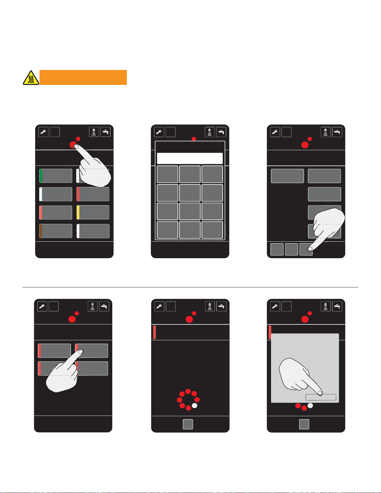
Press and hold the BKON dots
for 5 seconds
Select Cool Down Cool Down is in process Cool Down is complete, select
Continue and power off the
WVSC
Enter PIN number 4576 and
press Enter Select page 21.
4. 5. 6.
2. 3.
4576
Purge Water System

of 865
Service Prerequisites
Protect Air and Water Line and Connections
Remove the water, air and drain
lines if the repair requires their
removal.
Place a piece of tape over the
water, air and drain tubing to
prevent foreign debris from
entering the system.
Before reconnecting the water,
air and drain tubing ensure any
foreign debris is expelled.
1. 2. 3.

of 866

of 867
REMOVAL / INSTALLATION OF PARTS - TOWER
Top Cover (Tower)
Procedure Qty Remarks
(1)
(2)
(3)
Disassembly Order
Electrical connection
Screw (Phillips)
End cover
Top cover
4
2
1
Assembly is in the reverse order of disassembly
Unplug at wall from WVSC
(1)
(3)
(2)

of 868
Removal / Installation of Parts - Tower
Locking Lever
Procedure Qty Remarks
(1)
(2)
(3)
(4)
Disassembly Order
Screw
Axel Clamp
Axis
Locking lever
4
2
1
1
Assembly is in the reverse order of disassembly
(1)
(2)
(3) (4)
Requisite Service Removal / Installation: Top Cover (Tower) - Page 7

of 869
Plunger Assembly
Procedure Qty Remarks
(1)
(2)
(3)
Disassembly Order
Screw (Phillips)
Valve Cylinder
Plunger
4
1
1
Assembly is in the reverse order of disassembly
Remove the silicone water and air lines and microswitch connections
Requisite Service Removal / Installation: Top Cover (Tower) - Page 7
Locking Lever - Page 8
(1)
(2)
(3)
Removal / Installation of Parts - Tower

of 8610
Requisite Service Removal / Installation: Top Cover (Tower) - Page 7
Locking Lever - Page 8
Plunger Assembly - Page 9
Micro Switch Plunger Assembly
Procedure Qty Remarks
(1)
(2)
(3)
(4)
(5)
Disassembly Order
Screw
Washer
Spring
Micro Switch
Safety Slide
1
1
1
1
1
Assembly is in the reverse order of disassembly
Caution: spring is easy to loose
Disconnect wiring
(1)
(2)
(3) (4)
(5)
Removal / Installation of Parts - Tower

of 8611
Logo LEDs
Procedure Qty Remarks
(1)
(2)
Removal Order
Screws
LED Board 2
1
Assembly is in the reverse order of disassembly
Disconnect wiring connection
Requisite Service Removal / Installation: Top Cover (Tower) - Page 7
(1)
(2)
Removal / Installation of Parts - Tower

of 8612
Tower Solenoid Valves
Procedure Qty Remarks
(1) Removal Order
Solenoid Valves Assembly is in the reverse order of disassembly
Disconnect silicone tubing and voltage connectors
Requisite Service Removal / Installation: Top Cover (Tower) - Page 7
Removal / Installation of Parts - Tower

of 8613
Tower Left Side Panel
Procedure Qty Remarks
(1) Removal Order
Side Panel 1 Assembly is in the reverse order of disassembly
Requisite Service Removal / Installation: Top Cover (Tower) - Page 7
(1)
Removal / Installation of Parts - Tower

of 8614
Temperature Sensors - Thot and Tmix
Procedure Qty Remarks
(1)
(2)
Removal Order
NTC Tmix sensor
NTC Thot sensor 1
1
Assembly is in the reverse order of disassembly
Ensure water supply is turned off.
Requisite Service Removal / Installation: Top Cover (Tower) - Page 7
Tower Left Side Panel - Page 13
(1)
(2)
Removal / Installation of Parts - Tower

of 8615
Tower LED Left Side Lights
Procedure Qty Remarks
(1)
(2)
Removal Order
LED strip (Upper)
LED strip (Lower) 1
1
Assembly is in the reverse order of disassembly
Disconnect wire connections
Requisite Service Removal / Installation: Top Cover (Tower) - Page 7
Tower Left Side Panel - Page 13
(1)
(2)
Removal / Installation of Parts - Tower

of 8616
Tower Right Side Panel
Procedure Qty Remarks
(1) Removal Order
Right Side Panel 1 Assembly is in the reverse order of disassembly
Disconnect (6) wire connections before lifting side panel
Thot sensor wires are green
Tmix sensor wires are grey
(1)
Requisite Service Removal / Installation: Top Cover (Tower) - Page 7
Removal / Installation of Parts - Tower

of 8617
User Interface Display
Procedure Qty Remarks
(1)
(2)
(3)
(4)
(5)
(6)
(7)
(8)
Removal Order
Screw
Cover
Screws
PCB Board
Stand off
Touch screen
User Interface mounting screws
User Interface gasket
1
1
4
1
4
1
2
1
Assembly is in the reverse order of disassembly
Disconnect wire connections before removing boards
(1)
(2)
(3)
(4)
(5)
(6)
(7)
Removal / Installation of Parts - Tower
(8)

of 8618
Tower LED Right Side Lights
Procedure Qty Remarks
(1)
(2)
Removal Order
LED strip (Upper)
LED strip (Lower) 1
1
Assembly is in the reverse order of disassembly
Disconnect wire connections
Requisite Service Removal / Installation: Top Cover (Tower) - Page 7
Tower Right Side Panel - Page 16
(1)
(2)
Removal / Installation of Parts - Tower

of 8619
Drain Pan
Procedure Qty Remarks
(1)
(2)
(3)
(4)
Removal Order
Drain Pan Cover
Screws
Drain Pan
Seal
1
4
1
1
Assembly is in the reverse order of disassembly
Not shown
(1)
(2)
(3)
(4)
Removal / Installation of Parts - Tower
Table of contents
Popular Brewing System manuals by other brands

Royal Catering
Royal Catering RCBM-40N user manual

Blichmann Engineering
Blichmann Engineering Fermenator G4 Assembly operation maintenance

Fetco
Fetco TBS-122D Users guide and operator instructions

Ruby Street Brewing
Ruby Street Brewing Alpha Ruby owner's manual

Curtis
Curtis Gemini Satellite user guide

Grindmaster
Grindmaster VS-1.5 Specification sheet


