Black & Decker BD-29-DWH User manual

www.bdwaterheaters.com
P.N. 197882C
Electric Tankless Water Heaters
Models
BD-18-DWH, BD-24-DWH, BD-27-DWH,
BD-29-DWH, BD-36-DWH
118ºF
temp

2
Important Safety Guideline
THIS INSTRUCTION MANUAL SHOULD BE SAVED FOR FUTURE REFERENCE.
Denitions: Safety Alert Symbols and Words
This instruction manual uses the following safety alert symbols and words to alert you to hazardous
situations and your risk of personal injury or property damage.
DANGER: Indicates an imminently hazardous situation which, if not avoided, will result in
death or serious injury.
WARNING: Indicates a potentially hazardous situation which, if not avoided, could result
in death or serious injury.
CAUTION: Indicates a potentially hazardous situation which, if not avoided, may result in
minor or moderate injury.
(Used without word) Indicates a safety related message.
NOTICE: Indicates a practice not related to personal injury which, if not avoided, may
result in property damage.
WARNING:PLEASEREADTHISINSTRUCTIONMANUALTHOROUGHLYANDCOMPLETELY
BEFORE INSTALLATION & USE. FAILURE TO DO SO COULD CAUSE DAMAGE TO PROPERTY,
SERIOUS INJURY OR DEATH, AND VOID YOUR WARRANTY.
Please contact us directly, should you have any questions regarding your unit. We are available
Monday- Friday, 9AM-5PM EST at:
Phone: 1-844-746-6688
Email: [email protected]
For California residents / Pour les résidents de la Californie / Para residentes en California
WARNING: Cancer and Reproductive Harm -
www.P65Warnings.ca.gov.
AVERTISSEMENT: Cancer et Troubles de l'appareil reproducteur -
www.P65Warnings.ca.gov.
ADVERTENCIA: Cáncer y Daño Reproductivo -
www.P65Warnings.ca.gov.

3
Table of Contents
1. Safety Guidelines ------------------------------------------------------------------------------------04
2. About Your Black+ Decker Electric Tankless Water Heater ---------------------------------04-05
3.Selecting an Installation location -------------------------------------------------------------------05
4. Mounting Your Water Heater -------------------------------------------------------------------06-07
5. Plumbing Requirements and Precautions-----------------------------------------------------07-08
6. Plumbing Installation --------------------------------------------------------------------------------08
7. Electrical Requirements and Precautions ---------------------------------------------------------09
8. Electrical Installation-----------------------------------------------------------------------------10-13
9. Flow Rate --------------------------------------------------------------------------------------------14
10. Operation Guide---------------------------------------------------------------------------------14-15
11. Care and Maintenance--------------------------------------------------------------------------15-16
12. User Interface/Controls -------------------------------------------------------------------------16-17
13. Troubleshooting----------------------------------------------------------------------------------18-19
14. Reset Unit --------------------------------------------------------------------------------------------20
Before Installing
By installing this product, you acknowledge the terms of the manufacturer’s warranty and
authorized dealer’s return policy. Once the heater is installed, do not return the product to the
place of purchase. If you have any questions regarding the warranty or the product return policies,
please contact us by phone or email.

4
1. Safety Guidelines
Please read this manual thoroughly before installing & using the instant water heater. Failure
to comply with the safety, installation or operating instructions will void the product warranty.
Manufacturer and distributor of the product will not be liable for any damage or injury caused
by the failure to comply with the installation and operating instructions specied in this manual
or the improper use of the product. Ensure that this product is installed in accordance with the
national, state or local electrical and plumbing codes applicable to your area, and as specied in
our instructional guide to get the best performance from your Instant Water Heater.
This product has more than one power connection source. Do not attempt to install, clean, inspect,
disassemble, service or repair the water heater without shutting o all the power sources to the
unit on the main electrical panel using the circuit breaker.
WARNING: Failure to adhere might result in severe injury or death. The water heater must
be installed in compliance with all national, state, provincial and local electrical and building
regulations. We recommend that you consult a qualied electrician and a qualied plumber if
you have questions about anything relating to codes or regulations for this product.
This product is intended for household and indoor use only. Do not immerse in water.
The breaker used to power this unit must be grounded by means of the electrical panel.
The heater must be directly connected to dedicated circuit breakers on the main electrical
panel.
Do not install the heater where it may be subjected to direct sunlight, rain, splashing water,
moisture/humidity or freezing temperatures.
This unit is intended for heating water only. Do not attempt to use the unit for heating any
other kind of liquid.
2. About Your Black+ Decker Electric Tankless Water Heater
Congratulations on making the decision to purchase one of the best and nest Instant Water
Heaters currently available in the market today! Your new Instant Water Heater features advanced
water ow rate and temperature sensors which are designed to modulate power to the heating
elements to maintain a user-selected output water temperature range for 24kW / 27kW / 29kW:
86°F (30°C) to 122°F (50°C) (subject to the temperature of the incoming water).
WARNING: When selecting the water temperature setting of your Instant Water Heater’s
thermostat, factors such as safety and energy conservation should be considered. Continuous
exposure of the skin to water temperatures above 120°F (49°C) can result in severe burns or
death. The maximum temperature to be set on this Instant Water Heater’s thermostat is 122°F
(50°C). Always take precaution to feel the water before bathing or showering to make sure the
temperatures are not too hot. You are required to read and comply with the Time/Temperature
Relationship Chart on the following page to determine the right water temperature for your home.

5
Time/Temperature
Relationship in Scalds
120°F (49°C)
Exposure for more than 5 minutes
122°F (50°C) Around 3 minutes of exposure
You may require a 120°F (49°C) or lower thermostat setting
to prevent contact with “HOT” water, if you have small children,
disabled, or elderly persons in your home. The temperature of the
water is regulated by the electronic control on the front of the water
heater.
3. Selecting an Installation Location
• This Water Heater is designed for indoor installation only.
• It should not be installed in a location where it might be
subjected to freezing temperatures as the freezing of the
water in the Water Heater can lead to severe and irreversible
damages which are not covered under your warranty.
• The Water Heater should not be placed in a location that is dicult to access.
• Ensure that the water heater, as well as the power supplies and water connections, are
out of reach of children as the outlet water pipe can get very hot and touching can lead to
injury.
• Avoid installing your tankless water heater in a location prone to excessive humidity, moisture,
or dust, or in an area where it may be splashed with water or other liquids. DO NOT install
underwater pipes or air conditioning lines that might leak or condense moisture that could
then drip onto the heater. DO NOT install above electrical boxes or junctions.
• Do not install in areas which can be damaged due to leakage from the Water Heater. However,
safety measure such as suitable drip pan or an active water leak detector and shuto valve
should be installed in such areas that cannot be avoided.
Item # Unit dimensions (inches) Weight (lbs) Connections
BD-18-DWH 15.52 x 4.49 x 13.9 9.21 1/2”
BD-24-DWH 18.74 x 4.53 x 14.76 12.17 3/4”
BD-27-DWH 18.74 x 4.53 x 14.76 12.17 3/4”
BD-29-DWH 18.74 x 4.53 x 14.76 12.17 3/4”
BD-36-DWH 23.23 x 4.53 x 14.77 16.23 3/4”
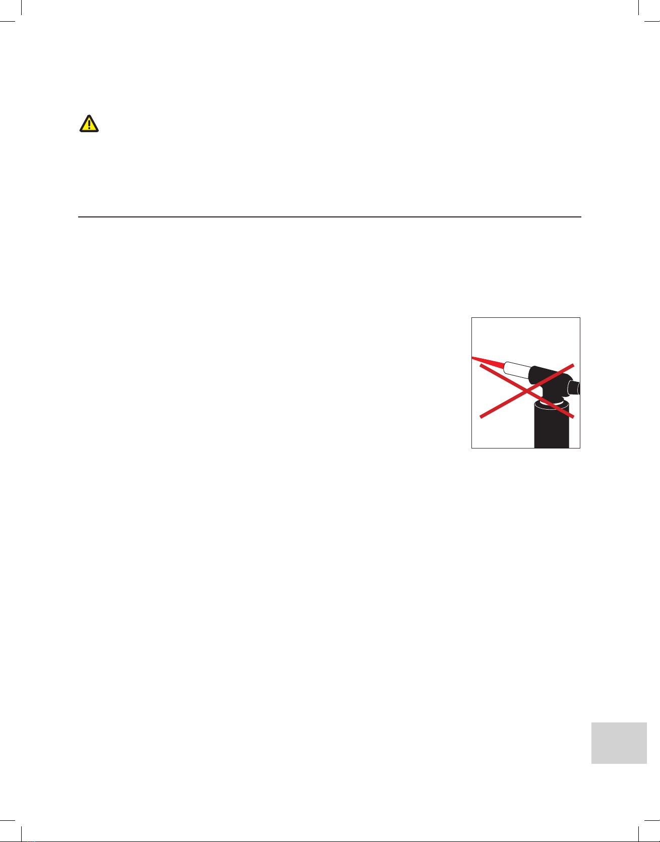
WARNING: Water heaters are heat producing appliances. In order to avoid damage, injury or
death, there shall be no materials stored against the water heater and proper care shall be
taken to prevent unnecessary contact (especially by children) with the water heater. UNDER
NO CIRCUMSTANCES SHALL FLAMMABLE MATERIALS, SUCH AS GASOLINE OR PAINT
THINNER BE USED OR STORED IN THE VICINITY OF THIS WATER HEATER OR ANY
LOCATION FROM WHICH FUMES COULD REACH THE WATER HEATER.
• Children, disabled and
elderly are at high risk of
being scalded.
• See instruction manual
before setting your desired
hot water temperature
• Always feel water before
bathing or showering

6
4. Mounting Your Water Heater
1. Your tankless water heater should be secured to a solid mounting surface with four screws,
(minimum 1” (25.4mm) long).
2. Ensure that the unit is level before fastening the screws in place.
3. The unit must be installed in an upright position with the water inlet and outlet at the bottom
of the unit. Do not install inversely with connections facing up or sideways with connections
facing right or left.
4. Do not install the unit above electrical boxes or junctions.
5. The water heater must be installed in a manner that prevents contact with ammable liquids
and gases. Keep these ammable materials at least two feet away from the heater and the
hot water outlet pipe. The water heater and the hot water outlet pipe must be secured, and
out of children’s reach to prevent tampering with controls or contact with an extremely hot
pipe.
6. If installing the heater on an upper oor or attic, make sure installation complies with the local
codes. Install a drip pan with drainage, or a leak detector and automatic shuto valve, to
prevent damage in case of any leakage.
a. Remove the appliance cover. (Heater cover) (gure 3)
b. Mount the unit on the wall with 4 screws at the marked points (gure 4)
c. Make sure the unit is leveled horizontally, with water inlets and outlets at the bottom
(g.5)
Fig. 3 Fig. 4
18kW
18kW
18kW
36kW
36kW
36kW
24/27/29kW
24/27/29kW
24/27/29kW
Fig. 5
Do not install upside down or on its side
Fig. 6
118
º
F
temp
Water
Pre-Filter

7
Recommended clearances: 12” (304.8mm) above and below the heater
6” (152.4mm) in front of and to the sides of the heater
CAUTION: Please keep any ammable materials at least 24” (609.6mm) away from the water
heater and hot water outlet pipe.
5. Plumbing Requirements and Precautions
• Please follow all plumbing instructions carefully. This product must be installed in accordance
with all national, state, provincial, and local plumbing codes. We recommend consulting with
your municipality or a qualied plumber if you have questions relating to plumbing codes for
your area prior to installing.
• The plumbing installation must be completed before the electrical installation.
• DO NOT solder any pipe with the unit connected to the pipe. The
heat from soldering may cause damage to the ow sensor. Doing so
will void the warranty.
• The use of a temperature pressure relief valve (T&P) is not required for
most installations because the tankless water heater does not use a
storage tank. UL Standard 499 does not require that a pressure relief
valve is used, although it may be needed to meet installation codes in
your area. In such cases, the pressure relief valve should be installed
in accordance with local codes. It is important to ensure that the unit
is operating correctly, and that air is purged from the valve prior to installing the water heater.
• A T&P valve is recommended for added safety when connecting to plumbing rated Metal,
Flex or High-Temperature CPVC piping.
NOTE: A pressure relief valve is required for installations in the Commonwealth of
Massachusetts and State of Kentucky. Please check your local installation codes
for any special requirements.
• The plumbing installation requires piping that can withstand pressure up to 8 BAR.
• The maximum operating water pressure for this unit is 150PSI / 10BAR. Residential plumbing
systems with unstable pressure or pressure above 5 BAR require the application of a pressure
reduction valve set to 4-5 BAR for optimal performance.
• The water supply ow rate must be at least 0.5 Gallons per Minute (GPM) to ensure proper
operation.
• Flexible water hoses are recommended to be used with your water heater when installing
your water heater. When connecting the inlet water pipe to the unit, use a wrench to hold the
unit’s connection, and another wrench to tighten so that the ow sensor on the unit will not
be loosened or damaged. Do not over-tighten the water inlet and outlet connections to avoid
severe internal damage to the water heater.
Fig. 7
Do not solder any
piping to the unit’s
Connection points

8
• We recommend the installation of a manual shut-o valve (ball valve) on the inlet and outlet
of the water heater to create a convenient shut-o point if future maintenance or servicing
is required. Before connecting the pipes to the water heater, it is highly essential to ush
the lines to eliminate all the plumbing paste or residue in the lines caused by any welding or
soldering.
• All the water pipes within 3 feet (1 meter) of the inlet and outlet connections are recommended
to be rated for high-temperature applications with 150°F (66°C) minimum.
• Before proceeding to the electrical installation, run water through the unit for several minutes
to ush out any air bubbles from the water line.
6. Plumbing Installation
STEP 1: Thoroughly ush cold supply line of debris.
STEP 2: Connect the HOT WATER line to the water heater OUTLET. The water heater outlet can
be seen on the left side of the heater when facing the unit. Connect the COLD-WATER line to the
water heater marked COLD WATER INLET which is located on the right side when facing the unit.
* Pre-heated water can be connected to the cold water inlet, where this unit will act as a booster.
STEP 3: After tightening both ttings at the water heater, several hot water faucets should be
opened to allow the ow of water through the water heater for at least 2 to 3 minutes. This process
purges all the air from the water lines and MUST be performed before turning on the power at the
unit.
FAILURE TO FOLLOW THIS STEP MIGHT CAUSE PERMANENT DAMAGE TO THE HEATING
ELEMENTS. (The power to the heater should be turned o and the air purged out of the lines
before turning the power on anytime maintenance is performed on the water heater or the homes
plumbing system, as air might have been introduced into the plumbing pipes.)
STEP 4: Carefully inspect all connections, units, and the pressure relief device for leaks after the
plumbing installation is completed. If there are no leaks present, you can proceed to the electrical
installation.
CAUTION: If you detect a water leak from the water heater at this point, turn o the water
supply at the shut o valve on the unit’s incoming water supply and contact us at 1-844-746-6688.
Plumbing Specications
18kW 24kW, 27kW, 29kW, 36kW
Minimum water ow to activate the unit 0.5 gpm
Working pressure 0.5–10 BAR (7–150 psi)
Tested pressure (maximum) 20 BAR (290 psi)
Water connections 1/2” NPT 3/4” NPT

9
7. Electrical Requirements and Precautions
Manufacturer recommends that this product be installed in accordance with all applicable national,
state, provincial, and local electrical codes. Consult a qualied and licensed electrician if you have
questions or are unsure about anything relating to codes for this product. The heater must be
connected to a dedicated circuit breaker on the main electrical panel.
WARNING: As with all electrical appliances, it’s crucial to rst shut o all power to the unit
directly at the fuse or breaker box before attempting to install, repair or disassemble this water
heater. Ensure that the breaker is shut o. SERIOUS BODILY INJURY OR DEATH COULD OCCUR
IF YOU IGNORE THIS WARNING.
CAUTION: All wiring (wire gauge), as well as circuit protection (breaker), must comply with
the U.S. National Electrical Code (NEC) in the USA or the Canadian Electrical Code (CEC) in
Canada. Failure to do so could lead to property damage, personal injury, and void your warranty.
Note: The Canadian Electrical Code generally requires that all supply wires and corresponding
circuit protection used for domestic hot water heating and hydronic heating applications be sized
to a minimum of 125% of the maximum current rating of the heater (check heater specication
details below).
Before installing this tankless water heater, ensure that sucient electrical power is available
in the home to handle the maximum amperage load of the applicable heater.
IMPORTANT NOTES:
18kW heater requires 2 set of wire and ground (see wiring diagram on page 11)
24kW, 27kW and 29kW heater requires 3 set of wire and ground (see wiring diagram on page 11)
36kW heater requires 3 set of wire and ground (see wiring diagram on page 12)
• Please see electrical specications by heater input and wiring diagram on the page 10 for
additional electrical information.

10
8. Electrical Installation
STEP 1: Take the wire pair and connect to the breaker (see wiring diagram). Be sure that the
breaker is connected to one black wire and one red wire. Be sure the power to the unit is shut o
using the dedicated circuit breakers in the main electrical panel.
STEP 2: Run the correct set of power cable wires from the circuit breaker in the main electrical
panel to the water heater by utilizing a suitable wire gauge which meets all applicable electrical
codes for the size of the breaker. Then, connect the power cable to the block terminal within the
water heater.
STEP 3: Unit requires a ground conductor for the incoming circuit.
STEP 4: DOUBLE CHECK the electrical connections and ensure the wire connections are
correct, tight and secure. It’s important to conrm that the right breaker size and wire gauge has
been used and that the unit has been connected to a ground in accordance with applicable codes.
Be sure to reattach the front cover of the unit with two screws.
STEP 5: Ensure that all the air has been purged from the water lines before turning on power to
the unit. Refer to STEP 3 in the plumbing installation section. Restore power to the unit through
the dedicated circuit breaker in the main electrical panel.
It is crucial to follow the wire connection as shown and ensure all connections are made
correctly for proper operation of the unit. The unit will not operate correctly, even though it
turns on and otherwise appears to function, if you mix up one set of wire with another.
Electrical Specications by Heater Input
Item # kW Max
Amps Required Breaker Req. Wire Size
BD-18-DWH 18 75 2 x 40A Double Pole 2 x 8/2 AWG with Ground
BD-24-DWH 24 100 3 x 40A Double Pole 3 x 8/2 AWG with Ground
BD-27-DWH 27 112.5 3 x 40A Double Pole 3 x 8/2 AWG with Ground
BD-29-DWH 29 120 3 x 40A Double Pole 3 x 8/2 AWG with Ground
BD-36-DWH 36 150 4 x 40A Double Pole 4 x 8/2 AWG with Ground
Power Rates
Item # 240V 220V 208V
BD-18-DWH 18,000 Watts 15,125 Watts 13,520 Watts
BD-24-DWH 24,000 Watts 20,166 Watts 18,026 Watts
BD-27-DWH 27,000 Watts 22,687 Watts 20,280 Watts
BD-29-DWH 29,000 Watts 24,368 Watts 21,782 Watts
BD-36-DWH 36,000 Watts 30,250 Watts 27,040 Watts
Your tankless water heater is now installed and ready to use! Follow the General Operating
Instructions to complete the setup.

11
Terminal Block in Unit
40 Amp
Double Pole
40 Amp
Double Pole
Unit Requires 10 AWG ground wire - one for each 240V circuit
L1L1 L2
8/2 AWG
8/2 AWG
L2
240V
240V
L1 L2 L1 L2
Wiring Diagram for 18kW
Terminal Block in Unit
40 Amp
Double Pole
40 Amp
Double Pole
40 Amp
Double Pole
Unit Requires 10 AWG ground wire - one for each 240V circuit
L1L1L1 L2
8/2 AWG
8/2 AWG
8/2 AWG
L2L2
240V
240V
240V
L1 L2 L1 L2 L1 L2
Wiring Diagram for 24kW, 29kW

12
40 Amp
Double Pole
40 Amp
Double Pole
40 Amp
Double Pole
40 Amp
Double Pole
Unit Requires 10 AWG ground wire - one for each 240V circuit
L1L1L1 L2
8/2 AWG
8/2 AWG
8/2 AWG
L2L2
240V
240V
240V
L1 L2 L1 L2 L1 L2
L1 L2
240V
L1 L2
8/2 AWG
Wiring Diagram for 36kW
Terminal Block in Unit

13
Testing the connections from your Breaker Panel to your unit
1. Measure the voltage by using AC multimeter.
2. Verify All circuit breakers are in the ON position. DO NOT turn on water while conducting this
test or turn on unit.
3. Make sure your Multimeter is set to testing Voltage and in AC position.
4. Place the multimeter probes between each L1-L2 pairing on the terminal block (see drawing) –
Each pairing should read approximately 240V.
5. Place the multimeter probes between each L1-L1 pairing and L2-L2 pairing on the terminal
block (see drawing) - Each pairing should read approximately 0V.
TERMINAL BLOCK IN THE UNIT
Measurement 1- Vac
Measurement 1- Vac
Measurement 1- Vac
L1 L2
240V
240V
L1 L2
240V
240V
L1 L2
240V
240V
L1 L2
240V
240V
L1 L2
240V
240V
L1 L2
240V
240V
L1 L2
240V
240V
L1 L2
240V
240V
L1 L2
240V
240V
TERMINAL BLOCK IN THE UNIT
Measurement 2- Vac
Measurement 2- Vac
Measurement 2- Vac
L1 L2
0V
240V
L1 L2
0V
240V
L1 L2
0V 0V
240V
L1 L2
0V 0V
240V
L1 L2
240V
L1 L2
0V 0V 0V
240V
L1 L2
0V 0V 0V
240V
L1 L2
240V
L1 L2
240V
18kW
24kW/ 29kW
36kW

14
9. Flow Rate
The chart below indicates maximum temperature rise for a given ow rate
INLET GROUND WATER TEMP
Item # kW 30°F 40°F 50°F 60°F 70°F
BD-18-DWH 18 4.1 3.06 2.46 2.04 1.75
BD-24-DWH 24 5.2 3.95 3.52 3.3 2.4
BD-27-DWH 27 5.4 4.15 3.65 3.4 2.7
BD-29-DWH 29 6.55 4.94 3.93 3.47 2.8
BD-36-DWH 36 6.2 5.15 4.4 3.9 3.1
Based on 105°F Output Water Temp
10. Operation Guide
Operating your new tankless water heater is similar to using any traditional water heating system.
However, it is essential that you carefully read all setup procedures, operating instructions and
tips to ensure the maximum performance and energy savings from your new water heater. We
recommend that all members of the household read these General Operating Instructions.
This electric water heater is designed to supply hot water. The unit contains heating elements within,
capable of heating water quickly on-demand for as long as you need it. Unlike a conventional tank
storage water heater, this unit is a tankless water heater that does not store hot water. However,
once you begin using the system, you will understand it works like a conventional tank system.
Tankless system delivers hot water instantaneously on demand. Since a tankless system does not
waste energy continually when heating water, i.e. idly sitting and losing heat in a storage tank, it
provides signicant energy savings than a conventional water heater.
With your new system, as soon as you turn on the hot water faucet, the demand for hot water is
detected by a ow sensor, and the high-power heating elements are activated. Sensors continually
monitor the water ow rate and measured the incoming and outgoing water temperature. Data is
transmitted to the system logic controls, which determines the exact amount of power required by
heating elements to heat the water to your desired temperature.
It is essential to keep in mind that all tankless water heaters are subject to a maximum ow rate. If
this ow rate is exceeded, the heater will not be capable of suciently heating water.
Also keep in mind that conventional tank heaters are set to high temperatures to prevent running
out of hot water quickly, and thus a large amount of cold water needs to be mixed in to reach a
comfortable level for washing and showering. Since this unit heats water on demand, it is designed
to heat to a lower temperature. This means you only need to mix in a small amount of cold water
or none at all.
Your hot water supply may also be aected by the incoming water temperatures as the season
diers. During winter, if the incoming water temperature is frigid, you might not be able to run
multiple hot water outlets at the same time as compared to the summer. However, you can run
showers back-to-back without having to wait for the water to heat.

15
Water Quality: One of the things which should be taken into consideration when installing and
maintaining the water heater is the quality of water. Water conditions outside the recommended
levels outlined below are not permitted and can damage the water heater. We reserve the right to
deny any warranty claim regarding damage suered due to use in water conditions that are not
in accordance with the table below. The water must be treated, and the heater ushed regularly
when this product is installed in an area that is known to have hard water that causes scale build-
up to prevent damage to the heat exchanger and heating elements. We recommend that a water
treatment device or water softener should be installed to maintain optimal performance of the
water heater in hard water areas.
Chart for Recommended Water Quality levels
pH Total
Dissolved
Solid (TDS)
Free
CO2 Total
Hardness Aluminum Chloride Copper Iron Manganese Zinc
6.5
-
8.5
Up to
500
mg/L
Up to
500
mg/L
Up to
200
mg/L
Up to
0.2
mg/L
Up to
250
mg/L
Up to
1.0
mg/L
Up to
0.3
mg/L
Up to
0.05
mg/L
Up
to 5
mg/L
11. Care and Maintenance
To ensure maximum performance of your water heater and to reduce the risk of a water leak, we
recommend the following maintenance:
• The water heater has minimally required maintenance procedures. Periodic inspections and
tests are always recommended for signs of damage or failure. Any damage, cracks, leakage
or weakness should be addressed and xed immediately. Do not over tighten any of the
connections. Over tightening the connection points could cause severe internal damage to
the unit.
• Remember that water heated at higher temperatures produces scale buildup much faster
than at lower temperatures. Having manual shut-o/maintenance valves installed on the inlet
and outlet of the water heater will allow access to ush the unit with a descaling solution. We
recommend routine maintenance once a year or once every six months if the water supply
has an unusually high level of mineralization (hard water)
• Clean the pre-lter on the inlet water side once every six months. Wash lightly to remove any
debris.
When any form of maintenance is carried out on the water heater or the home’s plumbing system
that may introduce air into the plumbing pipes, it is crucial to power o the water heater and purge
the air out of the lines before allowing the unit to power up.
FAILURE TO DO SO COULD RESULT IN PERMANENT DAMAGE TO THE HEATING ELEMENT
AND VOID YOUR WARRANTY.
When air is introduced into the plumbing system, follow the steps below to ensure the unit can
safely resume operation.

16
1.Shut o all power connections to the unit at the circuit breaker on the main electrical panel.
2.Perform the maintenance or servicing tasks.
3.Open one or more hot water faucets and allow water to run through the unit for several
minutes to purge any air from the heater and water lines.
This step must be performed before turning on power to the heater. Failure to complete
this step may cause permanent damage to the heating elements.
4.Reconnect power to the unit at the circuit breaker on the main electrical panel. Press and
switch the ON position.
5.With the water running through the unit, check and reset the temperature if necessary. The
recommended temperature setting is 118°F (48°C).
12. User Interface/Controls
Power
• Press button, the display will turn on
• Press button again, the display will turn o
Setting the Output Water Temperature
• To set the temperature, rst turn on a hot water
faucet and allow water to run through the
heater. The digital display lights up and shows
the current temperature setting.
• To increase or lower the temperature setting, press increase the temperature or to
decrease the temperature.
• Temperature can be set to any temperature from 86°F (30°C) to 122°F (50°C).
• A comfortable temperature for bathing and showering is between 105°F (41°C) and 110°F
(43°C).
• The recommended temperature setting is 118°F (48°C), which will deliver hot water for all
household needs at a maximum water ow rate.
CAUTION: A higher temperature setting is not recommended, as it can cause severe
scalding injuries to children and elderly persons. Higher temperatures also produce more
scale buildup in water heating devices.
118
º
F
temp
Press button to raise the
temperature (up to 122°F / 50°C)
or Press button to lower the
temperature (as low as 86°F / 30°C)

17
118ºF
temp
Starting the system for the rst time
1. Press button, to activate the heater to display outlet temperature.
2. With the water running through the unit, press or to adjust the temperature.
Freezing Temperatures
If the ambient temperature falls below 32°F (0°C), protect the heater from potential damage. Power
o the unit using the dedicated circuit breaker on the main electrical panel. Open a faucet slightly
to cause water to ow continuously through the device at a very low rate, without heating. Restore
power to the unit when temperature condition is normal.
If the water inside the heater freezes, it can cause damage that is not covered by warranty. If
you suspect water has frozen within the unit, do not turn it on until you are sure the frozen water
has melted, and there are no leaks in the unit. It is recommended to contact a qualied electrician
or the manufacturer for service in this situation.
“NOTICE: Hard water, water containing mineral concentration of over 250 mg/liter, may cause a
scale build up that can damage the product. In case of hard water it is recommended to use an
anti scale treatment. Damage caused by scale is not covered by the warranty.”
Digital temperature display
Temperature setting Buttons
Power Button
Cold water inlet
Hot water outlet
(to be connected to the main hot water pipe)

18
13. Troubleshooting
Before calling for service, check the troubleshooting list of common issues.
If you are unable to resolve a problem, contact your locally authorized distributor.
PROBLEM
ISSUE POSSIBLE CAUSE SOLUTION
No hot
water and
display do
NOT light up
Power outage or
faulty wiring. Check the power supply. Check the circuit breakers.
Make sure the breakers at main electrical panel are ON.
You may have a faulty breaker or unit may be wired
incorrectly.
Make sure the shuto valve on the unit’s incoming water
supply line is fully open.
The ow rate needed
to activate the heating
element (0.5 gpm) has
not been reached.
Increase the ow rate from the water supply source.
Clean the lter screen on the unit’s water inlet.
No hot
water and
display
DOES light
up
Reset the unit Refer to manual (Page 18) for diagram of reset points.
Make sure to shut all power on your breaker panel
before attempting to reset unit. All resets must be
pressed.
Potential internal part
failure Please call us for further technical assistance.
Water is
heated,
but not hot
enough.
The water ow rate
exceeds the heating
capacity of the heater.
Reduce the water ow rate at the faucet or slightly close
the shuto valve on the unit’s incoming water supply line
to reduce the water ow rate.
Voltage less than 240
Volts The heating elements on your water heater are designed
for 240 volts. When used with a lower voltage, they
produce less heating power. You may need to upgrade
to a larger input heater.
Crossed Wires. If it’s a new installation, double check the wiring to
conrm that it is correct.
Temperature setting is
too low. Increase the temperature setting on the unit.
Water pressure is less
than 0.5 bar (7 psi). Make sure the shuto valve is fully open, and the water
supply line is not blocked.
Mixing too much cold
water You do not need to mix as much cold water with your
tankless water heater compared to when you use a
conventional water heater. You may also have an anti-
scald feature on your faucet that is mixing cold water.
These types of faucets can usually be adjusted to reduce
the amount of cold water mixed.
Thermal loss due to
long pipe run. As the hot water from the heater runs through the hot
water delivery system to your faucet, some heat will be
lost especially if it has long distance to travel or the pipes
are cold. This is normal. You can compensate for this by
increasing the setting on your water heater if you need/
want hotter water.

19
Water is
heated,
but not hot
enough.
Voltage less than 240
Volts The computer chips in your tankless water heater are
programmed with the expectation that your incoming line
voltage is 240 volts. If you have less than 240 volts [i.e.
208V or 220V], it may aect the reading on your water
heater’s digital display and cause it to read slightly higher
than the actual output temperature. To compensate
for this, increase the setting on your water heater if you
need or want hotter water.
Water is too
hot. The water ow rate
through the heater is
too slow.
Increase the ow rate at the water outlet.
Temperature setting is
too high Switch to a lower temperature setting.
Water Temperature at
faucet is too hot. Check for too little ow, or if the set point temperature is
too high. This could possibly indicate a possible internal
part failure. Call us for technical assistance.
Heater
shuts o
during use.
Power outage or
faulty wiring. Check the power supply. Check the circuit breakers.
If the problem persists, please call us for further technical
assistance.
Water stops
owing. Possible Blockage in
water pipes or hoses. Make sure the main water line valve is fully open, and
there are no obstructions in the water supply line.
Water
temperature
varies from
hot to cold
during use.
Water pressure has
dropped below a
minimum level.
Increase the ow rate from the water supply source.

20
14. Reset Unit
As with all electrical appliances, it is crucial to rst shut o all power to the unit directly at the fuse
or breaker box before attempting to reset this water heater.
WARNING: SERIOUS BODILY INJURY OR DEATH COULD OCCUR IF YOU IGNORE THIS
WARNING.
Locate the three reset button locations as shown below and press all buttons. If you hear a “click,”
the unit has reset. If you nd that the unit needs to be reset quite often, please call our customer
service for further assistance. Proceed to turn on your breakers and power on the unit.
18kW
24kW, 29kW
36kW
This manual suits for next models
4
Table of contents
Languages:
Other Black & Decker Water Heater manuals
Popular Water Heater manuals by other brands

Rheem
Rheem 120 Volt Use & care manual

Rheem
Rheem RTH-53XN Specification sheet

Navien
Navien CH-180 installation manual

Hamworthy
Hamworthy FERNDOWN Installation, commisioning and maintenance instructions

State Water Heaters
State Water Heaters 710 Installation manual and owner's guide

Noritz
Noritz NCC300OD owner's guide

Omega
Omega OME 514-PV Installation manual and owner's guide

Atlantic
Atlantic Calypso FS 172L installation manual

Thermann
Thermann 26NG50C Installer manual

A.O. Smith
A.O. Smith SGE - 40 Installation, user and service manual

AEG
AEG DDLE Basis 11 Operation and installation

Rointe
Rointe SYGMA instruction manual