Black & Webster air-hydraulics AP1900D Assembly instructions

1
BLACK & WEBSTER
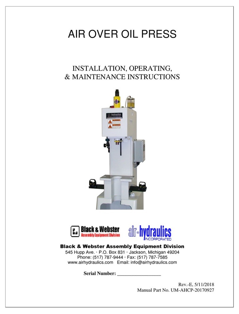
AIR PRESS
MODEL AP1900D
INSTALLATION, OPERATING &
MAINTENANCE INSTRUCTIONS
545 Hupp Avenue ▪ Jackson, Michigan 49204
Ph: 517-787-9444 ▪ Fx: 517-787-7585
www.airhydraulics.com ▪ info@airhydraulics.com
Serial No.__________________
Document ID: UM-BWAP-1900-D-20170926
Revision: Original

2
TABLE OF CONTENTS
Installation and Setup ………………………………………………………………………………………………………… 3
Maintenance ………………………………………………………………….…………………………………………………… 3
Disassembly ….………………………………………………………………….………………………………………………… 4
Troubleshooting Guide …………………………………………………………………………………………………….… 4 & 5
Pneumatic Circuit …………………………………………………………………………………………………………….…. 6
Part List ………………………………………………………………………………………………………………….………….. 7
Parts Drawing …………………………………………………………………………………………………………….………. 8
MACHINE GUARDING
Machine guarding is the responsibility of the user. Provisions must be made to protect the operator
and other employees from injury as a result of contact with work in progress, moving parts, mechanical
motions of the press, etc. Air-Hydraulics cannot provide “standard” guards for its products due to the
variety of tooling used by its owners. However, Air-Hydraulics will be happy to install guards and similar
safety devices for operator protection. These safety devices must be produced at the request of and
with the design approval of the purchaser.
WARRANTY
We warrant to the original user that all products of our manufacture will be free from defects in
material and workmanship and will possess the characteristics represented in writing by us. Claim for
breach of the above warranty must be made within a period of one (1) year from the date of delivery to
the user. Upon satisfactory proof of claim, we will make any necessary repairs or corrections, or, at our
option, replace defective parts at the factory, transportation charges prepaid. Charges for correcting
defects will not be allowed, nor can we accept goods returned for credit unless we are notified in writing
and the return or correction is authorized by us in writing. The FOREGOING IS IN LIEU OF ALL OTHER
WARRANTIES, EXPRESSED OR IMPLIIED, INCLUDING ANY WARRANTIES THAT EXTEND BEYOND THE
DESCRIPTION OF THE PRODUCT. This paragraph sets forth the extent of our liability for breach of any
warranty in connection with the sale or use of our products. It is understood we will not be liable for
consequential damage such as loss of profit, delays, or expense whether based on tort or contract.

3
INSTALLTION
1. Place press on rigid bench or table at a convenient height for operator. Bolt securely to the
bench.
2. Connect 100 P.S.I. filtered shop air supply (40 micron min) to 3/8 N.P.T. inlet port of air prep
assembly.
SET UP AND OPERATION
1. Loosen locknut and adjust pressure regulator until pressure gauge reads desired pressure
(100 P.S.I.). CAUTION: Do not operate at pressure greater than 125 P.S.I.
2. Adjust speed control valve to slow position by turning valve stem clockwise (or in).
3. Check to make sure safety sleeve assembly is in the correct position on the press before
operating
4. Keeping hands clear of shaft, actuate press by depressing palm buttons.
5. Release palm buttons. Shaft should return to fully retracted position (2 pos. circuit) or stop
movement (3 pos. circuit)
6. Remove safety sleeve from press.
7. Loosen locking nut and adjust stop nut to obtain desired stroke. Distance between bottom
of the stop nut and top surface of stop cap or frame is the stroke of the shaft. CAUTION: Do
not back off locking nut beyond top of threaded shaft. Doing so may damage packings.
8. Replace safety sleeve and re-actuate press.
9. If necessary, re-adjust stop nut, speed control and pressure regulator to obtain desired
setting. CAUTION: Never operate press unless safety sleeve is in place and hands are clear
of shaft.
10. Install tooling into hole provided in shaft, securing with set screw.
11. Install dies, nests or anvils onto base using tapped holes provided.
12. Make any final stroke, speed and pressure adjustments to obtain desired workpiece
configuration with tooling in place.
MAINTENANCE
LUBRICATION
Air presses are lubricated at the factory and should require no additional lubrication. However, if a
press is disassembled for service or replacement of parts, all internal surfaces should be coated with a
light bearing grease such as Lubriko M6 (Master Chemical Co.) or equivalent.
CUSHION ADJUSTMENT
Model AP 1900D employs an external cushion spring for the return stroke. The cushion is preset at the
factory and should require no further attention. However, if the machine should begin to “hammer”
during the return stroke, cushion adjustment may be necessary, as follows:
1. Remove safety sleeve from press
2. Loosen cushion adjustment locking nut.

4
3. Rotate cushion adjustment locking nut upward to increase spring compression, slightly.
4. Re-tighten locking nut.
5. Replace safety sleeve.
6. Adjust return speed control to maximum fast position.
7. Actuate press & check for “hammering” during the return stroke
8. If necessary, repeat cushion adjustment until ram returns gently to its rest position.
9. Re-adjust return speed control to obtain desired return stroke speed.
GIB ADJUSTMENT
Model AP 1900D has a square shaft retained by two adjustable gibs. If any side play or rotation is
noticed in the shaft of these models, a gib adjustment may be necessary. Adjustments as follows:
1. Along the centerline of the shaft at the front and right side of the press, two (2) set screws will
be found for each of the two (2) gibs.
2. Adjust set screws inward on one (1) gib at a time until all side play is removed from shaft. Do
not overtighten gibs or press may jam or operate erratically. Gibs should be just tight enough to
remove all side play and rotation from shaft.
PRESS DISASSEMBLY
Should press disassembly become necessary in order to service or replace parts, use extreme caution.
Remove air supply. Cylinder should be in retracted position. Ram & shaft may fall, be sure to block up
ram in the platen area. Remove hex screws holding cylinder cap in place. Now remove any fastener you
need to replace parts. Re-assembly should be approached with the same cautious manner. Torque
cylinder mounting fasteners to 23 ft. lbs. each.
Air-Hydraulics, Inc. maintains complete facilities at all times for the repair of air presses. If qualified
maintenance personnel are not available at a customer’s plant, the press may be returned to the Air-
Hydraulics, Inc. for service.
TROUBLESHOOTING GUIDE
PROBLEM
CAUSE
REMEDY
A. Shaft fails to extend
after hand valve
actuated or fails to
return to rest position
1. Insufficient air pressure
2. Speed control valve
closed or clogged
3. Power valve not shifted
1. Clean supply, adjust or
clean regulator
2. Open speed control
valve or clean blockage
3. Check for adequate pilot
air from hand valve & for
jammed spools

5
4. Hand valve clogged
5. Shaft bent
6. Gibs too tight
4. Clean hand valve
5. Replace shaft
6. Adjust gibs (see
maintenance)
B. Ram moves erratically
1. Gibs too tight
2. Insufficient lubrication
3. Air Leaking past packings
4. One or more valves
clogged or leaking
1. Adjust gibs (see
maintenance)
2. Re-lubricate press
3. Replace packing
4. Clean or repair valves
C. Excess rotation of shaft
1. Gibs loose or worn
1. Re-adjust gibs
(see maintenance)
D. Reduced force at a given
pressure
1. Air leaking past packings
2. Gibs too tight
1. Replace packings
2. Re-adjust gibs
(see maintenance)
E. Shaft “hammering” on
return stroke
1. Cushion spring loose or
broken
1. Replace spring if broken,
re-adjust cushion (see
maintenance)

6
PNEUMATIC DIAGRAM
SINGLE ACTING CYLINDER WITH
DUAL PALMS & ANTI-TIE DOWN
AP 1900
Length of Stroke 0-2” adjustable
Throat Depth 5.00”
Opening of Ram to Base 6.00”
Tool Hole in Ram .81 dia. X 1.50 deep
Force at 100 P.S.I. Up to 1900 lbs.
Ram Style Square with gib
Net Weight (less controls) 132 lbs.
Controls (optional) Flow Control Valve
Pressure Regulator
Pressure Gauge
High flow power valve
Exhaust Air Muffler
3 position valve (JOG)

7
PARTS LIST
AP1900 AIR PRESS
ITEM
PART #
DESCRIPTION
QTY
1
203035
Base
1
2
203075
Frame
1
3
203037
Cylinder
1
4
203038
Cylinder cap
1
5
203040
Cylinder base
1
6
203041
Ram
1
7
203076
Front cover
1
8
203077
Bronze gib
2
9
203044
Washer
1
10
203046
Cup retaining washer
2
11
203048
Spacer posts
3
12
203049
Retainer washer
1
13
203053
Stop nut
1
14
20305402
Spring cushion nut
1
15
203056
Shaft
1
16 (RK)
203045
Piston packing
2
17 (RK)
203050
Cylinder base packing
1
18 (RK)
203051
O-ring
2
19 (RK)
203052
Cylinder gasket
2
20
203055
Cushion spring
1
21
203108
Safety sleeve
1
22
203047
Spring return
1
23
203066
*
Repair kit
1
*Not shown on drawing (RK) Items in repair kit #203066

8
AP1900 PARTS DRAWING
Table of contents
Other Black & Webster Power Tools manuals
Popular Power Tools manuals by other brands

Bosch
Bosch GBH 2-20 D Professional Original instructions

Sealey
Sealey SB973 instructions
Max
Max CN565S Operating and maintenance manual

Makita
Makita GRH08 instruction manual

Parkside
Parkside PASSK 20-Li A1 Translation of the original instructions

SCHUNK
SCHUNK KSC2 40 Installation and operating instructions
TE Connectivity
TE Connectivity 2031676-1 Assembly instructions

Ozito
Ozito ROU-5000 instruction manual
Worx
Worx WX473 Original instructions
Northern Industrial Tools
Northern Industrial Tools 12Volt Chainsaw Sharpener 141259 owner's manual
BASETech
BASETech ZD-70D operating instructions
Ryobi
Ryobi EPN6082C Original instructions
