2
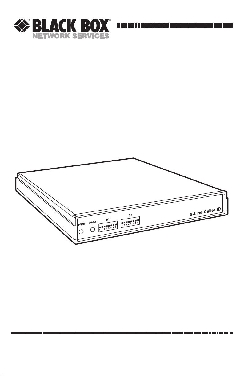
4- AND 8-LINE CALLER ID
FCC REQUIREMENTS FOR TELEPHONE-LINE EQUIPMENT
1. The Federal Communications Commission (FCC) has established rules which
permit this device to be directly connected to the telephone network with
standardized jacks. This device must not be used on coin lines. Its use on
party lines is subject to state tariffs; for more information, contact your state’s
public-utility commission or corporation commission.
2. If this device is malfunctioning, it might also be causing harm to the
telephone network; this device should be disconnected until the source of the
problem can be determined and until the repair has been made. If this is not
done, the telephone company may temporarily disconnect service. If possible,
they will notify you of this in advance. But if advance notice isn’t practical, you
will be notified as soon as possible. You will be advised of your right to file a
complaint with the FCC.
3. If you have problems with your telephone equipment after installing this
device, disconnect this device from the line to see if it is causing the problem
If it is, contact Black Box or an authorized agent.
4. The telephone company may make changes in its technical operations and
procedures. If any such changes affect the compatibility or use of this device,
the telephone company is required to give adequate notice of the changes.
5. If the telephone company requests information on what equipment is
connected to their lines, inform them of:
a. The telephone number that this device is connected to.
b. The name and part number of this device.
c. The ringer equivalence number (REN): 0.0 B.
d. The service order code (SOC): 9.0F.
e. The facility interface code (FIC): 02LS2, 02GS2.
f. The USOC jack required: RJ-14C for TE120A, RJ-11C for TE121A.
g. The FCC registration number.
Items (c) and (g) can be found on the unit’s FCC label. The ringer
equivalence number (REN) is used to determine how many devices can be
connected to your telephone line. In most areas, the sum of the RENs of all
devices on any one line should not exceed five (5.0). If too many devices are
attached, they might not ring properly.
6. In the event of an equipment malfunction, all repairs should be performed by
Black Box or an authorized agent. It is the responsibility of users requiring
service to report the need for service to Black Box or to an authorized agent.