Black Line G6 Operating instructions
G6 MULTI-UNIT CHARGER INSTALLATION
AND OPERATION GUIDE
©2023 Blackline Safety Corp G6 Multi-Unit Charger Installation and Operation Guide | 1
Rev. 02 2023-10-16
OVERVIEW
This manual applies to the following G6 multi-unit chargers:
•ACC-G6-CHG-05-NA 5 Unit, North America
•ACC-G6-CHG-25-NA 25 Unit, North America
•
ACC-G6-CHG-05-EU 5 Unit, Europe
•
ACC-G6-CHG-25-EU 25 Unit, Europe
•ACC-G6-CHG-05-AZ 5 Unit, Australia/New
Zealand
•ACC-G6-CHG-25-AZ 25 Unit, Australia/New
Zealand
WARNING: G6 multi-unit chargers shall only be powered by an external 24V AC/DC adaptor that is certified to
IEC-62368-1:2018 or an equivalent standard (e.g., part number TR70MA240-01E03 VI, AC input range: 100 to 240
Vac, manufactured by Cincon Electronics Co. LTD). The maximum current from the external 24V AC/DC charger
must not exceed 0.7A for the 5-unit charger (ACC-G6-CHG-05-XX) and 3A for the 25-unit charger (ACC-G6-CHG-
25-XX). The DC plug type of the external 24V AC/DC adaptor is Inner + Outer - (OD: 5.5 x ID: 2.1 x L:12mm).
G6 MULTI-UNIT CHARGERS
G6 multi-unit chargers are available in a 5-unit or 25-unit configuration, allowing you to charge
multiple G6 devices at the same time.
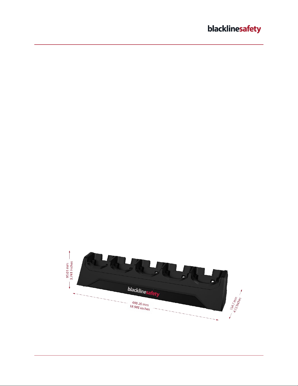
5-UNIT CHARGER (ACC-G6-CHG-05-XX)

G6 MULTI-UNIT CHARGER INSTALLATION
AND OPERATION GUIDE
©2023 Blackline Safety Corp G6 Multi-Unit Charger Installation and Operation Guide | 2
Rev. 02 2023-10-16
What’s Included:
•5 slot charger
•24V AC/DC adaptor
•AC power cord appropriate for the geographical region
•G6 Multi-Unit Charger Installation and Operation Guide
25-UNIT CHARGER (ACC-G6-CHG-25-XX)
What’s Included:
•25 slot charger
•24V AC/DC adaptor
•AC power cord appropriate for the geographical region
•G6 Multi-Unit Charger Installation and Operation Guide
INSTALLATION
INSTALLING THE MULTI-UNIT CHARGER ON A HORIZONTAL SURFACE
Prior to installing the multi-unit charger, assess the intended installation area to make sure it meets
the following criteria:
•G6 must be charged in a clean, gas-free environment between 0°C (32°F) and 45°C (113°F).

G6 MULTI-UNIT CHARGER INSTALLATION
AND OPERATION GUIDE
©2023 Blackline Safety Corp G6 Multi-Unit Charger Installation and Operation Guide | 3
Rev. 02 2023-10-16
•The multi-unit charger must be installed on a horizontal flat, stable surface such as a table,
work bench, or desk.
CAUTION: The multi-unit charger should not be installed on vertical surfaces such as a wall
without the optional wall bracket (ACC-G6-CHG-05-KIT-XX or ACC-G6-CHG-25-KIT-XX). If you
are mounting the multi-unit charger on a wall, refer to Installing the Multi-unit Charger on a
Vertical Surface.
Optionally, you can anchor the multi-unit charger to the horizontal installation surface using the
screw and keyholes in the base. There are two tabs at the back of the charger, and two or four
keyholes (depending on the size of your charger) under the charger for screws.
To install the multi-unit charger:
1. Place the base of the multi-unit charger on a clean, flat, stable surface.
2. Plug the 24V AC/DC adaptor into the 24V DC input port on the back of the multi-unit charger,
then attached the supplied AC power cord to the 24V AC/DC adaptor.
3. Plug the AC power cord in to an AC outlet with a voltage within the AC input range of the
adaptor.
To install and anchor the charger on a horizontal surface:
Required Tools
•Screws suitable for your mounting surface (not provided)
•Drill with appropriately sized drill bit
•Screwdriver
•Pencil to mark holes
1. Using the measurements provided, mark the areas where the screws will go.
2. Using a drill bit and screws appropriate for the surface you are drilling into, drill into the
surface, using your marks as guides. Ensure the hole is shallower than your screw length.
3. Use a screwdriver to fit the screws that go underneath the charger into the holes you drilled.
CAUTION: Do not insert the screws that go through the tabs at the back of the panel yet.
4. When all screws for the keyholes on the bottom of the charger are installed, lift the multi-
unit charger, and lower it down onto the screws. Slide the charger forward to lock the
charger in place.
5. Use a screwdriver to fit the screws that go through the tabs on the back of the charger in
place.
6. Plug the 24V AC/DC adaptor into the 24V DC input port on the back of the multi-unit charger,
then attached the supplied AC power cord to the 24V AC/DC adaptor.
7. Plug the AC power cord in to an AC outlet with a voltage within the AC input range of the
adaptor.
If the panel needs to be removed, simply remove the screws from the back tabs, then slide the
panel back and lift it up to unhook it from the screws.
G6 MULTI-UNIT CHARGER INSTALLATION
AND OPERATION GUIDE
©2023 Blackline Safety Corp G6 Multi-Unit Charger Installation and Operation Guide | 4
Rev. 02 2023-10-16
INSTALLING THE MULTI-UNIT CHARGER ON A VERTICAL SURFACE
To install the charger on a vertical surface:
IMPORTANT: You will need two people to complete the installation. Where possible, ensure the
mounting unit is aligned with the wall studs.
Required Tools
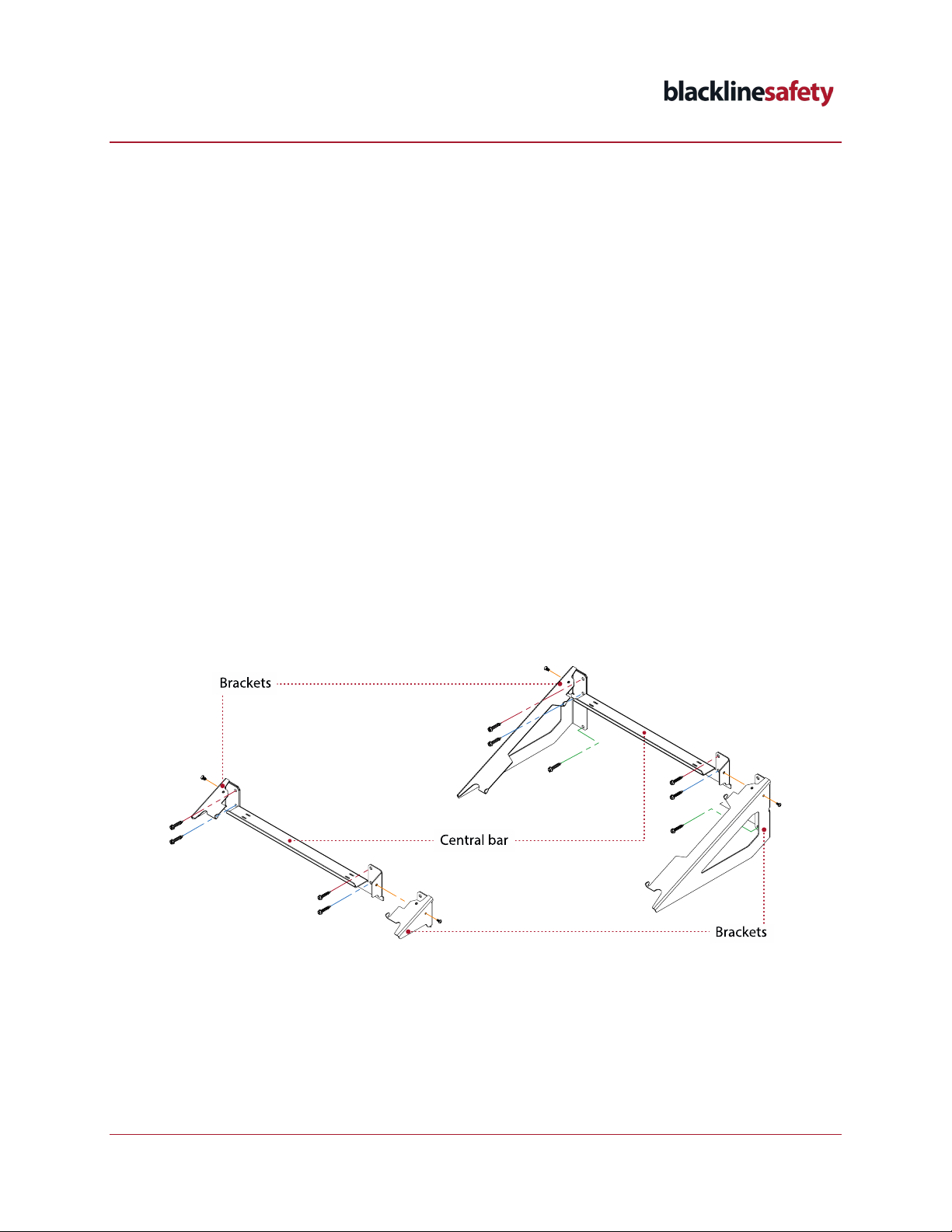
•Wall mounting bracket kit (3 parts: 2 mounting brackets, one central bar and 2-M4
screws) (ACC-G6-CHG-05-KIT-XX or ACC-G6-CHG-25-KIT-XX)
•Screws and anchors suitable for your mounting surface (not provided – M6 screws at an
appropriate length for your mounting surface are recommended)
•Drill with appropriately sized drill bit
•Pencil or chalk to mark holes
•Measuring tape
•Level
•Screwdriver
1. Slide the two mounting brackets onto the central bar. Ensure the brackets fit snugly into the
grooves on the outside of the central bar.
G6 MULTI-UNIT CHARGER INSTALLATION
AND OPERATION GUIDE
©2023 Blackline Safety Corp G6 Multi-Unit Charger Installation and Operation Guide | 5
Rev. 02 2023-10-16
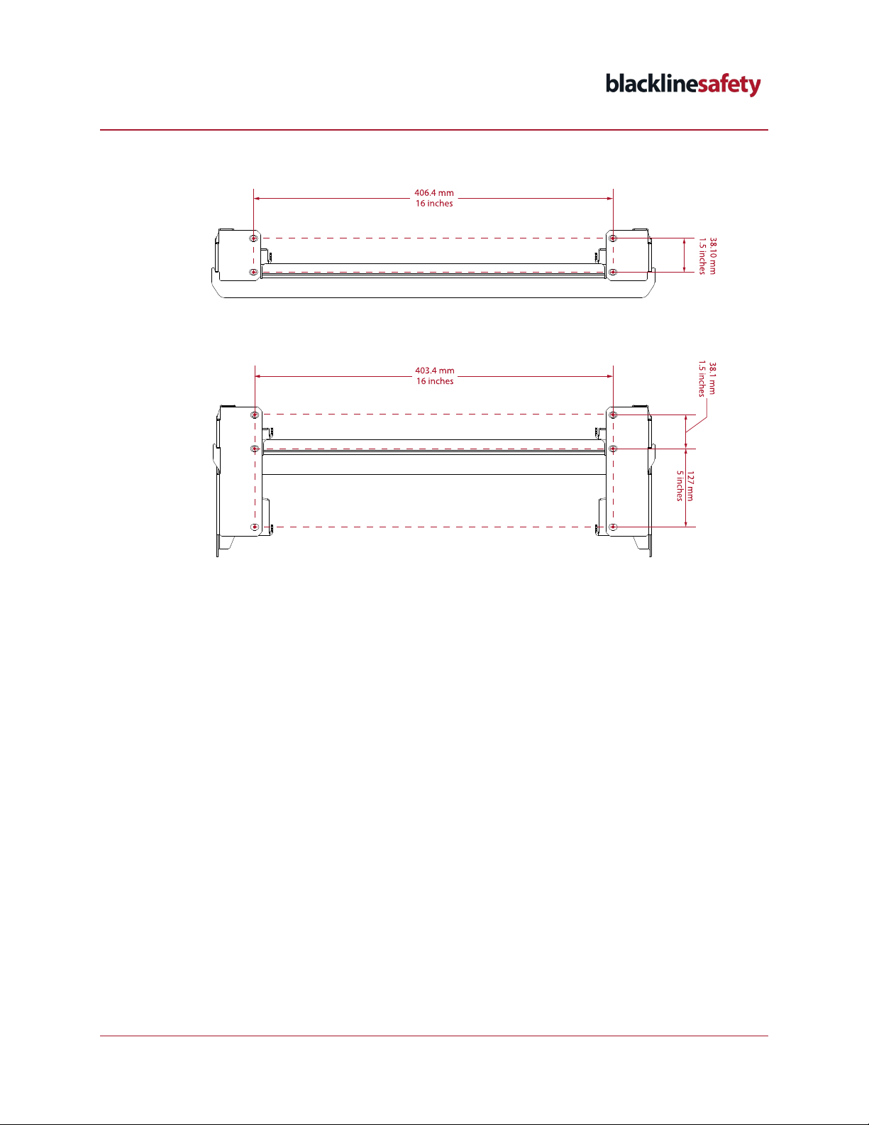
2. Using the measurements provided, mark the areas where the screws will go.
3. Using a drill bit appropriate for the surface you are drilling into, drill into the surface, using
your marks as guides. Ensure the holes are the appropriate length for your anchors (not
provided).
4. Insert anchors that are appropriate for your mounting surface. For example, if you are
mounting on a wall, use drywall anchors.
5. Have one person hold the assembled mounting unit on the wall, lining up the screw holes
with the holes you drilled.
6. Place a level along the central bar to ensure the mounting unit is even.
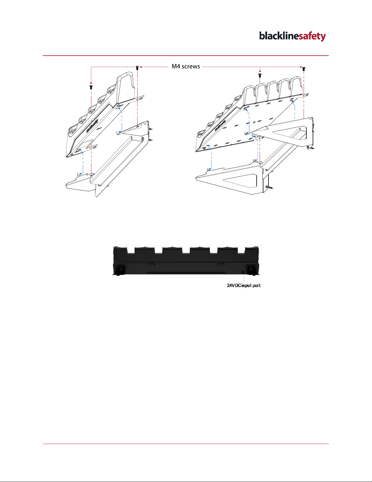
7. Use a screwdriver to insert the provided screws through the mounting unit into the wall, as
shown in step 1.
8. Line up the multi-unit charger’s bottom keyholes with the hooks on the mounting unit.
9. Slide the charger toward you to lock it in place.
10. Use a screwdriver to insert the provided screws through the tabs on the back of the charger
into the bracket.
G6 MULTI-UNIT CHARGER INSTALLATION
AND OPERATION GUIDE
©2023 Blackline Safety Corp G6 Multi-Unit Charger Installation and Operation Guide | 6
Rev. 02 2023-10-16
11. Plug the 24V AC/DC adaptor into the 24V DC input port on the back of the multi-unit charger,
then attached the supplied AC power cord to the 24V AC/DC adaptor.
12. Plug the AC power cord in to an AC outlet with a voltage within the AC input range of the
adaptor.
13. If your setup allows, place the charging block on the shelf at the back of the mounting unit
(behind the multi-unit charger) to prevent tension on the charging cables.
If the panel needs to be removed, simply remove the screws from the back tabs, then slide the
panel back and lift it up to unhook it from the screws.
CHARGING G6 IN A MULTI-UNIT CHARGER
G6 multi-unit chargers should only be operated and stored within the following environmental
parameters:
•Operating temperature: 0°C to 40°C (32°F to 104°F)
•Humidity: non-condensing, up to 95%
•Storage temperature: -20°C to 60°C (-4°F to 140°F)
G6 MULTI-UNIT CHARGER INSTALLATION
AND OPERATION GUIDE
©2023 Blackline Safety Corp G6 Multi-Unit Charger Installation and Operation Guide | 7
Rev. 02 2023-10-16
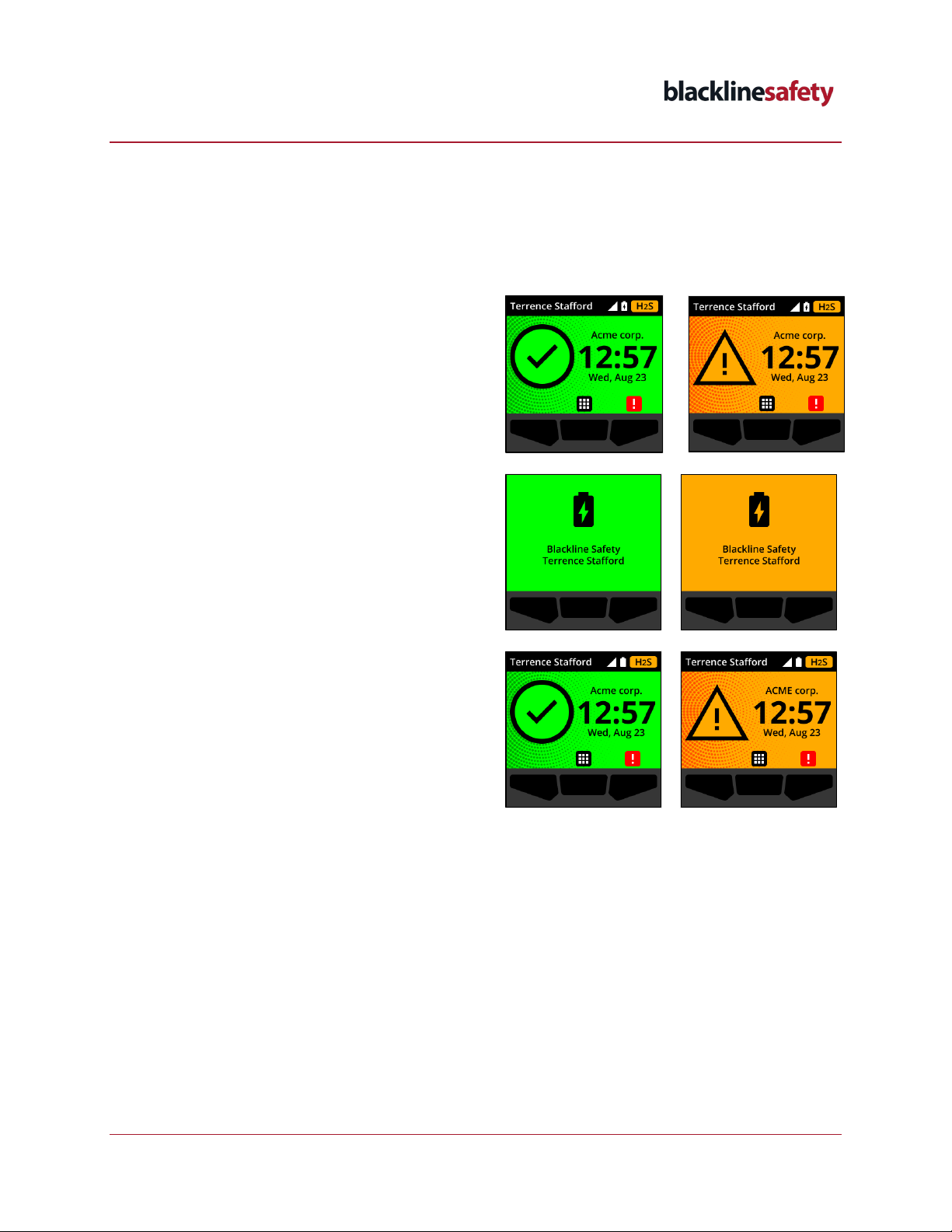
To charge G6 devices in the multi-unit charger:
1. Place G6 devices into the charging slot. One of the following screens will display, indicating
your device is charging. If the battery icon in the banner does not change to the charging
icon, remove G6 and try inserting it again.
NOTE: Each slot has a magnetic connector that secures G6 in place.
If G6 is powered on during charging, the
Home screen reflects the device’s charging
status.
If G6 is powered off during charging, the
Battery Charging screen opens, reflecting the
device’s battery status.
Once G6 is charged and removed from the
multi-unit charger, the Home screen reflects
the current device (event) status.
This manual suits for next models
6
Table of contents


