Black Lion Audio Sparrow MK II User manual

Black Lion Audio
1801 W. Belle Plaine Ave, StE 105
Chicago, IL 60613
773-549-1885
V1.0
1

WARNING
FOR YOUR SAFTEY, PLEASE READ THE FOLLOWING:
GROUNDING:
For your safety, do not defeat t e grounding connection on t e power cord. Use t e device only w en it is properly
grounded.
WARN NG:
If t e safety ground on t e device is defeated, a fault condition in t e unit or in t e
system to w ic it is connected could result in full line voltage between c assis
and eart ground potential. Severe injury or deat can result.
LIQUIDS, WATER, AND MOISTURE:
T e device s ould not be used near water, or w en it is wet. Care s ould be taken so t at it remains dry. Be sure to
keep t e device away from rain or ot er moisture.
POWER:
T e device s ould be connected to a power supply only of t e type described in t e operating instructions and as
marked on t e rear panel.
POWER CORD:
Power supply cords s ould not be routed under carpets, or w ere t ey are likely to be walked on or pinc ed by items
placed upon or against t em. Do not use power cables t at ave become worn or frayed.
MULTIPLE-INPUT VOLTAGE:
T e equipment may require t e use of a different power plug, cord, or bot , depending on t e available power
connection in your area. Connection is made by means of an IEC standard power socket. T e rear panel voltage
label indicates t e voltage required for satisfactory operation of t e unit. Before connecting t e unit to t e mains
supply, ensure t e fuse fitted is t e correct type and rating, as is indicated on t e rear panel adjacent to t e fuse
older.
EXTERNALLY ACCESSIBLE FUSE RECEPTACLE:
Replace t e fuse wit t e same type, current, and voltage ratings only. Do not use t e device wit out t e fuse cover
properly in place.
SERVICING:
To reduce t e risk of fire or electric s ock, t e user s ould not attempt to service t e device. Servicing s ould be
referred to qualified service personnel. Contact Black Lion Audio if you need assistance.
T e Black Lion Audio Sparrow MK2 as been tested and found to comply wit t e limits for a class A digital device
pursuant to Part 15 Subpart B of t e Code of Federal Regulations Title 47.
47CFR Part 15.19
T is device complies wit part 15 of t e FCC Rules. Operation is subject to t e following two conditions: (1) T is
device may not cause armful interference, and (2) t is device must accept any interference received, including
interference t at may cause undesired operation.
47CFR Part 15.21
C anges or modifications to t is equipment not expressly approved by Black Lion Audio may void t e user's
aut ority to operate t is equipment.
2

Table of Contents
Overview....................................................................................................................................................4
Installation / Connections...........................................................................................................................5
Power................................................................................................................................................5
Combo Jacks.....................................................................................................................................5
AES, ORX, S/PDIF........................................................................................................................5
Word Clock In/Out...........................................................................................................................5
Inputs and Outputs.....................................................................................................................................6
Power, Power Switch, and Power LED............................................................................................6
Inputs, Signal/Clip LEDs, and Input rim.......................................................................................6&7
Digital Audio Output Formats..........................................................................................................7
Word Clock......................................................................................................................................7&8
Clocking the Sparrow MK II................................................................................................................8&9
Specifications...........................................................................................................................................10
roubleshooting.......................................................................................................................................10
3
I. Overview
T e analog to digital converter (ADC) is a vital component in any recording or broadcast studio.
Limitations of t e ADC can compromise t e performance of t e w ole system. Inter-modulation
distortion (often referred to as IM or IMD), armonic distortion (THD), and frequency or p ase
response anomalies, may manifest t emselves as an overall deterioration in t e perceived sound
quality of t e system. Fortunately, your c oice of a Black Lion Audio ADC will elp eliminate
t ese problems, offering you unmatc ed product performance and reliability.
For years Black Lion Audio as researc ed t e root causes of audio signal degradation during t e
conversion process, and we strive diligently to offer our findings in t e finest quality converters
available.
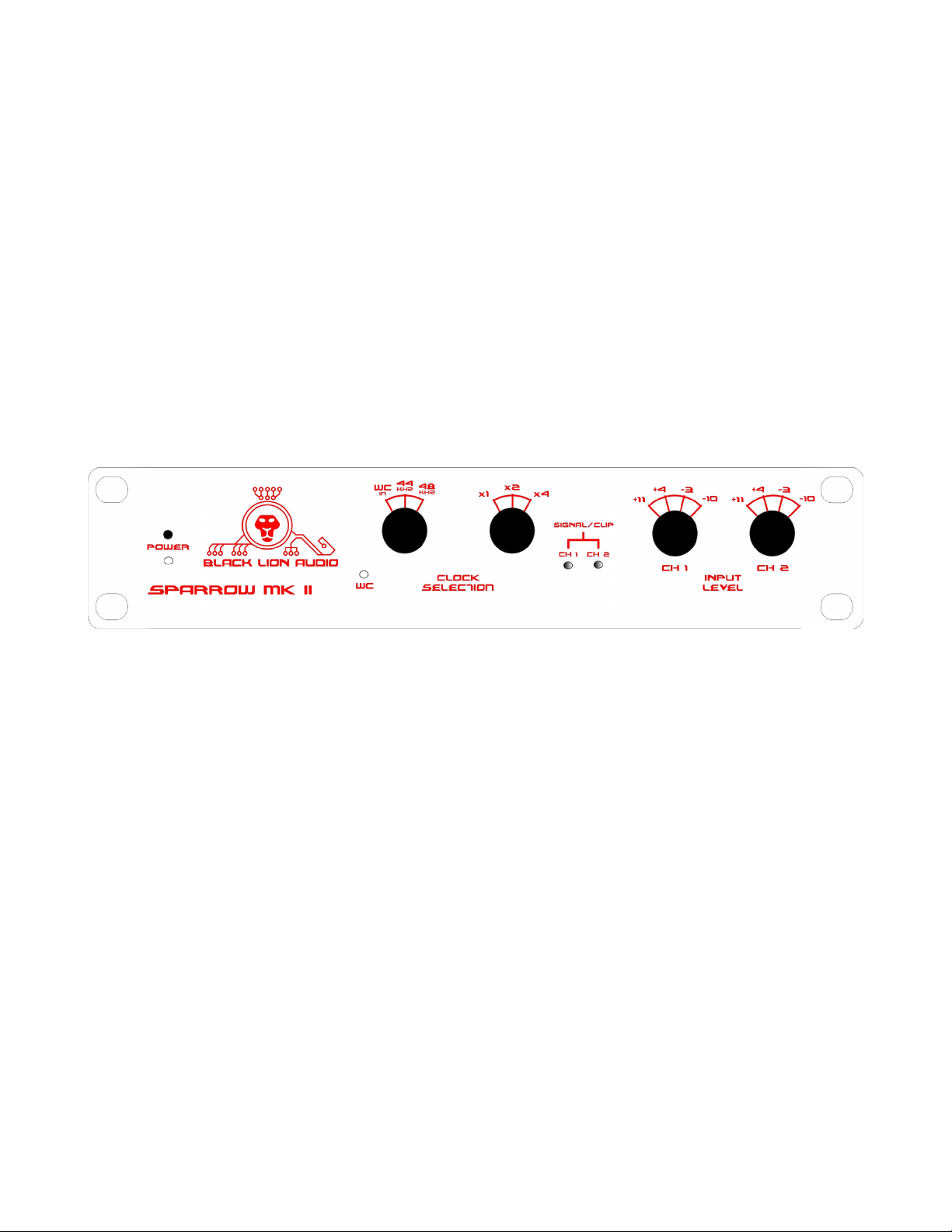
T e BLA Sparrow MKII ADC is a stereo analog to digital converter offering four levels of input trim
adjustment. Signal present/clip LEDs allow proper input trim adjustment for a wide variety of
sources. Digital audio outputs are in industry standard S/PDIF and AES/EBU formats. A word
clock input and output are offered for sync ronization to ot er audio sources and destinations in
t e studio.
4

II. nstallation / Connections
AFTER YOU HAVE UNPACKED THE UNIT
Save all t e packing materials - t ey will be andy s ould it become necessary to transport or
s ip t is device. Please inspect t is unit carefully for any signs of damage incurred during
transportation. It as undergone t oroug inspection and testing prior to packing and was
s ipped in perfect condition. If, owever, t ere are any signs of damage, notify t e
transportation company wit out delay. If necessary, contact Black Lion Audio for furt er
assistance.
Do not install t e unit in a location subject to excessive eat, dust or mec anical vibrations.
1. Power
Power is applied via an IEC standard connector. If you are uncertain ow to properly apply power
to t e unit, please call your nearest Black Lion Audio dealer for assistance. T ey will be appy to
elp you.
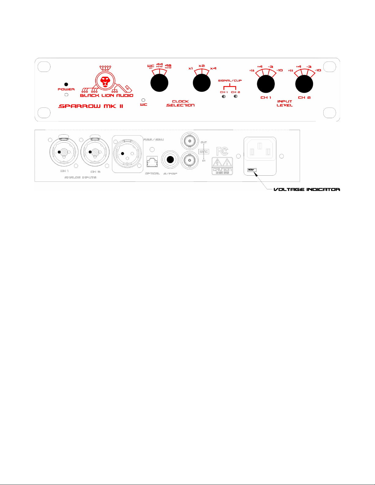
2. Combo Jacks
Audio is input via t e “combo” connectors on t e back panel. T ese support eit er a balanced or
unbalanced standard “XLR” or 1/4” type connection. For best performance, we recommend
using only balanced connections via good quality cables and connectors.
3. AES, TORX, S/PDIF
Digital audio outputs are available via t ree different connectors on t e back panel. AES/EBU
output is available via a standard XLR male-type connector, w ile S/PDIF output is available on
t e “RCA” style connector and via an optical “TORX” (TOSLINK®) connector.
4. Word Clock In/Out
Word clock in and out are available on BNC connectors on t e back panel. T e cables used to
connect to t ese s ould be of good quality construction, as s ort as possible, and routed away
from potential sources of noise (t ey are unbalanced).
5
III. nputs and Outputs
1. Power, Power Switc , and Power LED
Make sure t e voltage selector switc on t e IEC connector is set to t e appropriate voltage for
your locale. Power can be 50Hz or 60Hz, and t e voltage selections available are 110V and
240V. T e voltage indicator indicates t e selected mains voltage. T e power switc on t e front
of t e unit applies power to t e unit’s internal power supply.
A power LED is located on t e front panel below t e power switc . T is LED will begin to blink
w en power is applied. T e blinking will continue (for about a minute) w ile t e ADC is executing
its power-on calibration sequence. After t e converters ave been calibrated, t e LED will remain
lit. Once t e blinking stops, digital audio will be output from t e unit.
2. Inputs, Signal/Clip LEDs, and Input Trim
Input signal levels can vary from typical consumer “-10” type sources to professional “+4” types
and beyond. Input trim adjustments are provided on t e front panel to assist in matc ing levels
to a variety of sources. “Consumer” audio sources will usually require t e greatest input
sensitivity. Setting t e Input Trim fully clockwise may provide t e best matc ing for t ese types
of devices. “Pro” audio sources, on t e ot er and, will typically output a muc ig er nominal
level. A setting labeled “+4” as been provided to accommodate sources wit t ese ig er
signal levels. An intermediate setting as also been provided, labeled “-3”.
Finally, a lowest trim setting is available for use wit certain audio sources w ic can provide
very ig output levels. Hig er end mixing consoles, as well as many types of outboard gear
often ac ieve very ig “ eadroom” or dynamic range by being capable of generating signals in
excess of +20dBu! T e BLA ADC can easily andle outputs from t ese sources wit t e setting
labeled “+11” (fully counterclockwise) on t e front panel.
6

Note t at at all settings, t e actual signal level w ic will clip t e converter (possibly causing
unwanted distortion) is typically 15dB over t e level set on t e front panel. T us, in t e
“-10” setting, a peak signal of greater t an +5dBV will clip t e unit. In t e “-3” setting, a signal
greater t an +12dBV will cause clipping, and so on.
To assist in setting t e appropriate input level for your application, Signal/Clip LEDs are located
on t e front panel. T ese indicators derive t eir level from t e digital audio signal and won’t
function until after t e converters ave been calibrated. T e LEDs illuminate (green) at a low
intensity w en t e audio reac es a peak amplitude greater t an 60dB below t e Full Scale of t e
digital signal (-60dBFS). T e illumination becomes brig ter until t e signal reac es -12dbFS, and
t en becomes an “amber” color. W en t e unit is driven very close to clipping (-3dbFS), t e lig ts
turn a solid red. T is is a good indication t at t e input level s ould be reduced!
3. Digital Audio Output Formats
All digital audio outputs output 24-bit audio at sample rates selectable from 44.1kHz to 192kHz.
Please refer to t e Audio Engineering Society (AES3 standard) or t e International
Electrotec nical Commission (IEC 60958 standard) for specific details on t is format.
a) AES
Digital audio is output on t e AES connector. T e output format is compatible wit connections
typically labeled “AES”, “AES-3”, “AES/EBU”, IEC 60958”, etc. A 110 O m cable s ould be used
to connect t is output to anot er device.
b) S/PDIF
Digital audio is also output on t e “RCA” type connector labeled “S/PDIF”. T is output format is
also in conformance wit IEC 60958 Type II “unbalanced” connections. A 75 O m cable s ould
be used to connect t is output to anot er device.
c) TORX/Optical/TOSLINK®
Anot er output labeled “Optical” is located on t e rear panel. T is connector also carries IEC
60958 Type II signals, but over a fiber optic connection. A standard TOSLINK® cable s ould be
used to connect to t is output.
4. Word Clock
T e word clock determines t e rate at w ic audio will be sampled by t e ADC. T ere are a
number of options for selecting t e word clock configuration on t e ADC.
a) Word Clock Input Source
T is selection allows t e user to c oose between internal sample rates of 44.1kHz, 48kHz, and
an external word clock source. W en an internal (44.1 or 48kHz) clock source is selected, t e
ADC generates its own word clock and no external equipment is needed. W en an external clock
7

source is selected (and t e clock is present), t e ADC will detect it on t e “Word In” BNC
connector on t e rear panel.
For convenience, w en t e ADC as detected and sync ronized to a valid clock source, internal or
external, a “Lock” lig t (labeled “WC” for word clock. will illuminate on t e front panel of t e unit.
In t e case of an external clock source, t is lig t indicates t at t e clock signal is being received
successfully. T is lig t also indicates t at a valid clock is present a t e word clock output
connector.
b) Word Clock Multiplier
T e word clock multiplier is used to control t e frequency of t e ADC’s internally generated
sampling rate. T is setting applies to internal clocks only. T e x1 setting s ould be selected for
word clock rates of 44.1kHz and 48kHz. T e x2 setting s ould be selected for word clock rates of
88.2kHz and 96kHz. T e x4 setting s ould be selected for word clock rates of 176.4kHz and
192kHz.
c) Word Clock Input Signal
T e word clock input is used to drive t e ADC’s sampling from an external clock source. T e
input must receive a signal greater t an 2.4Vp-p for proper operation. BLA recommends using a
low jitter clock source like t e Micro Clock MK2. T is input is not terminated internally, and does
not require an external termination.
Please see Section IV “Clocking t e BLA A2D” for additional important information on clocking
converters.
d) Word Clock Output Signal
T e word clock output can be used to drive ot er devices in t e studio for digital audio sample
rate sync ronization. T e output is 5Vp-p and as a 75 O m “source termination.”
Please see Section IV “Clocking t e BLA A2D” for additional important information on clocking
converters.
IV. Clocking the Sparrow MK
Muc confusion in t e audio industry as resulted from different manufacturers implementing
and recommending different clocking standards and levels. Termination and voltage are t e two
parameters t at most often cause different units to be incompatible. Hig speed digital signals,
like clocks and digital audio, can cause cables and distribution systems to ex ibit be aviors
w ic may seem strange and unintuitive to t e audio engineer. T ese be aviors are commonly
termed “Transmission Line Effects.” W ile it is beyond t e scope of t is manual to t oroug ly
cover transmission line t eory, we can quickly give t e competent user some rules of t umb t at
we feel will consistently yield satisfactory results.
Termination is t e single most commonly misunderstood concept. A good way to t ink of t e
8

termination of a transmission line (like a clock distribution line, for instance) is as follows:
A proper termination tells the signal to stop!
Black Lion Audio clocks are terminated at t e source (t e clock output) wit a 75 O m
termination. T is is done to properly drive a 75 O m cable and as t e effect of “killing” any
reflections t at come back from t e line. Reflections are most commonly caused by
unterminated “stubs” on t e line, like an unterminated clock input for instance.
Note t at alt oug it is possible to use “Tee” connectors and “daisy-c ain” multiple converters
clock inputs from a single clock source, t is is not t e preferred met od as t is is ow stubs are
created. Terminating eac stub on t e line does not work eit er, as multiple terminations load
down t e source (t e circuit driving t e clock output) unnecessarily.
After muc experimentation and after seeing different approac es tried t roug out t e industry,
we ave found t at t is approac (multiple “T”s and terminations) becomes overly complicated
quickly, and often confuses even tec nically competent users.
T e preferred met od we ave found is to use a “source-terminated” output (like a Black Lion
clock output) to drive one, and only one, un-terminated input directly t roug a s ort cable run.
T e unterminated input does cause a reflection but, because of t e source termination, t e
reflection is negated at t e beginning of t e line and t e input sees only t e original intended
clock signal.
To recap; clocking BLA devices is simple:
* Drive one and only one clock input from a clock output.
* Use short, high uality, cables.
* Avoid “T” splitters and terminations if possible.
If you do not ave good cables, or are still confused, DON’T PANIC! Black Lion can elp. Just give
us a call and we’ll elp you get your ADC up and running in no time.
9

V. Specifications
THD: < 0.001% (20kHz BW, 20-20kHz, @-10dBFS)
IMD: < 0.002% SMPTE (1:1) 60Hz + 2k~20kHz typical
Crosstalk : < 100dB (@20kHz all gain settings)
Clipping: > +24dBu (gain full CCW)
Clock Input level : 2.4Vpp ~ 5.5Vpp
Clock Output: Square Wave, @5Vpp, 75O ms Output Impedance
Frequency Response: (@ 192kHz Sample Rate) 19Hz ~ 87kHz
Size: 10.25” x 8” x 1.75”
Weig t: 5lbs
S ipping Weig t: 6.5lbs
Power Consumption: 14W
Recommended operating temperature: 0 ~ 40°C
Storage Temperature: -25 ~ 50°C
Input Impedance: 10k O ms
Output Noise: -120dBFS (-122dBFS for t e “W ite Sparrow”) typical
Meter Type: Peak Reading
All specifications: 20kHz BW, 150 O m source impedance, and 44.1kHz sample
rate unless ot erwise noted.
Note: TOSLINK® is a registered trademark of oshiba, used without their permission.
10
Table of contents
Other Black Lion Audio Media Converter manuals

Popular Media Converter manuals by other brands

Korenix
Korenix JetCon 2201-w Quick installation guide

Converters.TV
Converters.TV 612 Operation manual

tams elektronik
tams elektronik SD-34 manual

DIODE LED
DIODE LED DI-1804 installation guide

DYNAPAR
DYNAPAR SLIM Tach SL85 instruction manual

Communications Specialties
Communications Specialties Scan Do Pro II user manual


