Ude IPU-1025 Quick guide

DC IN
LAN
AUDIO LINK +24VDC
SPK
INPUT
TL
TL
MADE IN
SPAIN
IPU-1025
135,2
179,5
41,2
45,0
FRONT
SIDE
REAR
OUT
IN
OK
DEVICE CALL
FAULT CONFIG NET
ACTIVITY
USB
ON
IPU-1025
Engineered and made in E.U.
IPU-1025
4.1.-
4.2.-
INDEX
5
4
8
7
5
28
8
10
13
22
25
27
27
29
29
15
16
3
2
PAGE
1.- DESCRIPTION
2.- TECHNICAL DATA
3.- TYPICAL APPLICATION OF IPU-100
5.- DEVICE CONFIGURATION (WEBSERVER).
5.1.- Home page (HOME)
5.2.- SIP Configuration (SIP)
5.3.- Extension SIP Configuration (EXTENSIONS)
5.4.- Device configuration (DEVICE)
5.5.- Network configuration LAN. (NETWORK)
5.9.- (RESET TO FACTORY)Reset to factory default
5.10.- Remote Reboot (REBOOT)
5.3.1.- Erasing & editing
5.3.2.- P.A. zones edit page
Installation - Configuration - Use
IPU-1025 Audio over IP
5.6.- Time configuration (TIME).
5.7.- Date configuration (DATE).
5.8.- Password configuration device (PASSWORD).
4.- DESCRIPTION OF CONNECTIONS.
Front view.
Rear view.
AUDIO IP DECODER with 25W Class D AMPLIFIER
291
610.440A
rev.1
EQUIPOS Y SISTEMAS MEGAFONÍA / INTERCOM PUBLIC ADDRESS SYSTEMS
Tel.: +34 934 772 854 / +34 609 914 787

DC IN
LAN
AUDIO LINK +24VDC
SPK
INPUT
TL
TL
MADE IN
SPAIN
IPU-1025
OUT
IN
OK
DEVICE CALL
FAULT CONFIG NET
ACTIVITY
USB
ON
IPU-1025
Engineered and made in E.U.
1.- DESCRIPTION
IPU-1025
292
610.440A
Rev. 1
The public address system for IP networks of UNION DESARROLLOS ELECTRONICOS allows the creation of conventional PA
and security systems, allowing us to interconnect with IP devices following SIP standard. Unión Desarrollos Electrónicos Audio
offers the server that will centralize and coordinate all communication of IP paging elements ensuring maximum
functionality of all of them, with minimal risk.
The has included many functions within the same device: decoder and audio manager.
With these functions allow the user to:
- Connect to loudspeakers, horns or trumpets directly through the integration of a class D amplifier with a maximum power of 25W.
- This amplifier has a low impedance output allows direct connection to PA speakers.
- Connect the decoder within an IP network.
- Connect an audio source.
- Connect a microphone with or without phantom power for simple messaging to the IP network.
The decoder becomes the key element to ensure compatibility with all loudspeakers and horns/trumpets on the PA
portfolio of UNION DESARROLLOS ELECTRONICOS, so that you can use to adapt older installations today. Besides
concentrating on just one set of IP decoder with built-in amplifier allows savings in space, power and price of the final device.
The IP system is suitable for any type of installation: schools, sports centers, industrial areas, department stores, airports, etc ... .
It is recommended for remote management applications such as: Remote management of parking, remote management facilities
on installation that require sound systems.
The allows encoding and decoding multiple audio formats, such as G-711 and G-722 suitable for Voice and PCM suitable
for Background Music environment applications.
The may be operated in two different ways, making it very versatile in any installation:
- 24V AC Adaptor (18..30V).
- 24V backup battery (18..30V).
The configuration by the technician is done by accessing to the integrated Webserver using a password, but if the user or
operator needs to monitor the status of it, then also can be done remotely, just knowing the IP address of the device.
IPU-360 SIP
IPU-1025
IPU-1025
IPU-1025
IPU-1025
IPU-1025
Installation - Configuration - Use - IPU-1025

2.- TECHNICAL DATA
293
- 10/100Mbit, Full/Half duplex, Autonegociación, AutoMDI/MDI-X, Compatible con PoE (IEE802.3af).
- LINK and ACTIVITY leds included.I
- RJ-45 socket type (8 pins).
- IP protocols supported:
IPV4 (IPV6 not supported).
DHCP (Auto/Manual).
TCP/IP.
UDP.
RTP.
SIP.
HTTP, AnnounceIP.
The IPU-100 can only process non-fragmented packets.
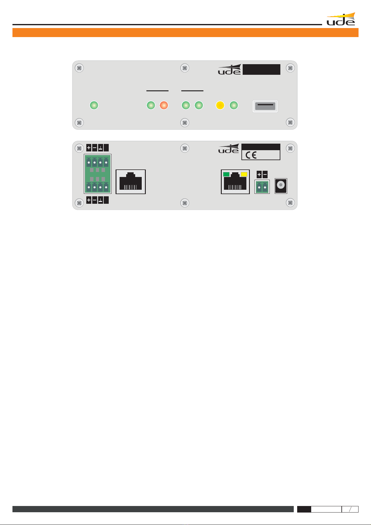
AUDIO LINK port
Dedicated port to the connection with the IP Paging Desk (IPU-100P), that includes:
- Digital Control Bus: RS485 (115200bps, 8bits, No Parity, 1 stop bit, No flow Control).
- Balanced Audio Output (0dB, 0.775mVrms/600Ω).
- Balanced Audio Input (0dB, 0.775mVrms/10KΩ).
INPUT port
Dedicated port to connect to analog input audio devices:
- Differential Microphone (2mVrms/600Ω, Phantom 12V).
- LINE IN (300mVrms/10KΩ, connection to auxiliary Background Music devices).
- Activation through REMOTE IN (Close Contact) or VOX function.
SPK port
Dedicated port to the connection of loudspeakers, horns or trumpets at low impedance:
- Audio Output (25W/8Ω, THD <10%).
- Activation of REMOTE OUT.
- Close Contact (INCOMING call on-live). Maximum Load capability: 0.5A at 24Vdc.
- Open Contact (no INCOMING call received).
USB port
USB 2.0 Type A.
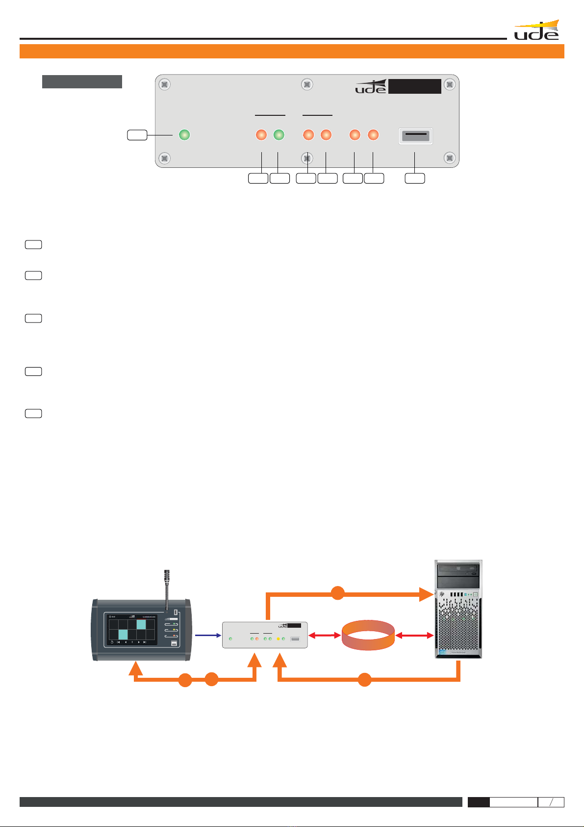
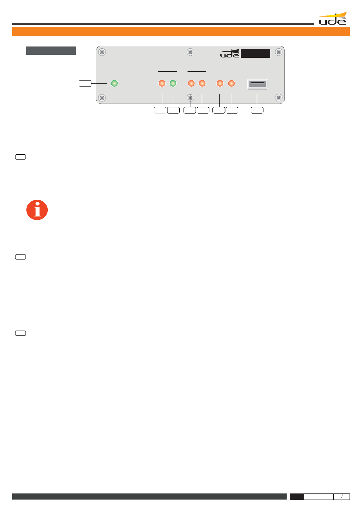
LEDs (only informative) Power , LAN Activity , mode, OUTCOMING call ( ),
INCOMING call ( ), Device properly register on SIP server ( ),
Failure on Device ( ).
ON (NET ACTIVITY) CONFIG CALL OUT
CALL IN DEVICE OK
DEVICE FAULT
System Clock Backup Supply
3V Lithium Battery, CR2025 type (Not rechargeable)
Audio Format (Encoder / Bandwidth)
Included Codec:
G.711 (u-Law) 8 bits logarithmic compression and 8KHz sampling frequency.
G.711 (a-Law) 8 bits logarithmic compression and 8KHz sampling frequency.
G.722(ADPCM).8 bits Adaptive Linear Compression and 16KHz sampling frequency.
PCM. 16 bits without compression and 8KHz sampling frequency.
PCM. 16 bits without compression and 16KHz sampling frequency.
.
.
Outcoming Call to default
extension activation
REMOTE IN input (switch type).
- Close Contact to start and hold the out coming call.
- Open Contact to cancel the out coming call.
VOX control (Threshold level and Pre/Post activation time settings).
Remote Management
Security Level
Password system of 8 alphanumeric characters.
Power
Main:
- AC Adaptor (recommended): 24Vdc (IPW-25).
0.9A PPTC internal fuse (resettable).
- Backup: Battery (external): 24Vdc (18..30V).
0.9A PPTC internal fuse (resettable).
Consumption
32W máx. at 24Vdc. (IPU-100P mode: 38W)
Operation temperature
-5 a +45ºC (0 a +40ºC, recommended)
Storage temperature
-15 a +60ºC
Humidity
5% a 95%, witthout condensation
Weight
0.6 Kg
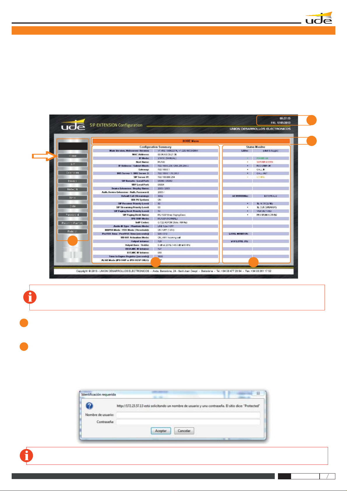
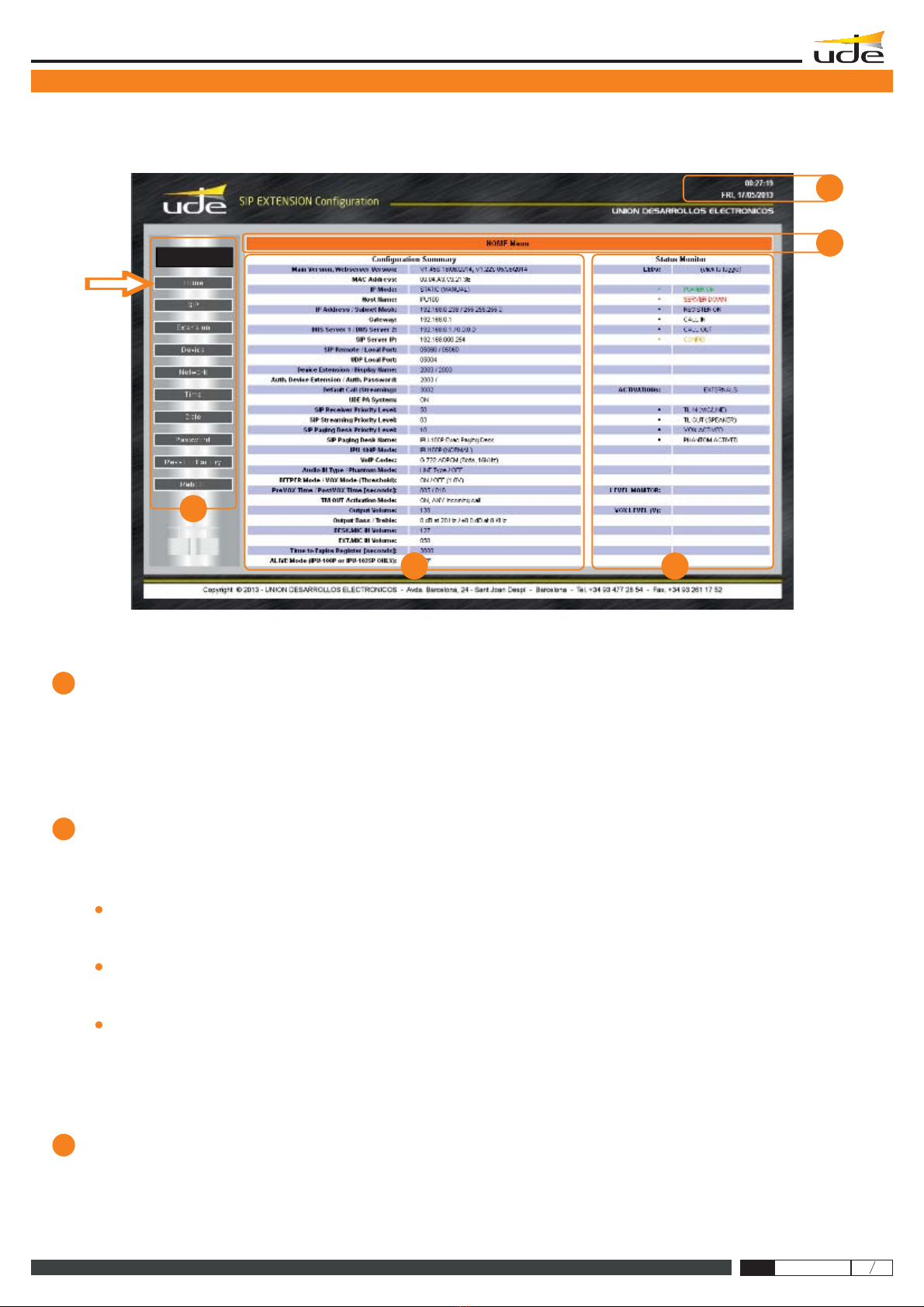
Using the Webserver built-in in the device the following remote features are available:
- Functionality Supervision.
- Password Management.
- Configuration of : SIP, LAN, Time/Date, Device.
LAN port (Ethernet)
PIC32 CPU (Microchip™ powered).
CPU Principal
TECHNICAL FEATURES VALUES
610.440A
Installation - Configuration - Use - IPU-1025
IPU-1025
Rev. 1
64 Kbps
128 Kbps
128 Kbps
256 Kbps
64 Kbps
Bandwidth

3.- TYPICAL APPLICATION OF IPU-100
294
IPU-1025
3.TYPICALAPPLICATION OF IPU-100.
Figure1 provides anexampleconfiguration of thePAsystemfor IPnetworks ofUDE.
IPU-100P
IPU-360
IPU-1025 UNION
DESARROLLOSELECTRONICOS.
The audio decoder IPU-1025 model is the element that allows the decoding of audio sent digitally to a conventional audio
signal to be amplified conveniently and connected directly to speakers, horns or trumpets.
The IP Paging Desk ( ) with color touch screen, where the operator can select the zones where the message
must be activated once you press and hold the button of "PTT" (Talk).
In addition, the SIP server ( ) which acts as intermediary between all IP devices connected to the LAN working.
As can be seen our devices can connect to the wide range of speakers, horns and trumpets of
IPU-1025
IPU-1025
IPU-1025
IPU-1025
IPU-100
IPU-100P
IPU-360
IP
OUT
IN
OK
DEVICE CALL
FAULT CONFIG NET
ACTIVITY
USB
ON
Engineered and made in E.U.
OUT
IN
OK
DEVICE CALL
FAULT CONFIG NET
ACTIVITY
USB
ON
Engineered and made in E.U.
OUT
IN
OK
DEVICE CALL
FAULT CONFIG NET
ACTIVITY
USB
ON
Engineered and made in E.U.
OUT
IN
OK
DEVICE CALL
FAULT CONFIG NET
ACTIVITY
USB
ON
Engineered and made in E.U.
IPU-100
MESSAGE
SPEECH
USB
FAULT
ON
IPU-100P
610.440A
Installation - Configuration - Use - IPU-1025 Rev. 1

IPU-1025
OUT
IN
OK
DEVICE CALL
FAULT CONFIG NET
ACTIVITY
USB
ON
IPU-1025
Engineered and made in E.U.
1
4657328
4.- DESCRIPTION OF CONNECTIONS
295
4
3
2
1
5
LED ON
LED NET ACTIVITY
LED CONFIG
LED CALL IN
LED CALL OUT
1a
2a
3a
4a
. This indicator shows that the equipment is properly powered and that the main application is running.
. This indicator shows the data activity when is connected to an Ethernet LAN.
When you receive IP packets should be the LED blinking.
. This indicator shows that session of configuration (Setup) by Webserver is open.
. This indicator is set when an incoming call (active decoder mode) is received and accepted, and is active while the call emitter keep
the channel open. Once emitter point drop the call, the server of the installation disable the call and the CALL IN indicator will turn off.
When the LED remains off indicates that the IPU-1025 is not getting any calls.
. This indicator is activated when the IPU-1025 device is the generator of a voice call, there are two types of call:
Using a IP Paging Desk Controller (IPU-100P) connected to the IPU-1025 reports that the user is performing an outgoing call to one or more areas.
So that the LED is turned on the following sequence of events must happen.
.The IPU-100P device makes a request to the IPU-1025, to provide an outgoing call to one or more paging zones selected by touch
screen and Pressing the PTT button (talk).
.The IPU-1025 processes the request and sends the information through the IP network to the server to communicate with selected
decoders. The Call Out LED has not yet been activated, communication is not established.
.The IPU-360 processes and sends packets with information to the IPU-100 that communication begins feasible. At this time the CALL
OUT LED turns ON.
.This indication remains active until the user releases the call button. At which the IPU-1025 reports to the installation server the call
cancelling and when the cancellation is accepted, then the CALL OUT indication is turned off, releasing all resources used during
communication.
Encoding directly the audio signal connected to INPUT (+/-) of the IPU-1025, the device is able to detect the audio modulation and generate a call
to the extension that has been programmed on the Webserver. The IPU-360, Public Address IP manager, will determine the priority and connect
the call to the appropriate paging zones. Later will confirm the call to the IPU-1025, audio encoder, which turns on the CALL OUT LED.
While audio modulation was present or remote input was active, the IPU-1025 input will be encoded and sent through the IP network showing your
work status through the LED CALL OUT.
NOTE:This LED appears blinking (orange) while WEBSERVER session is open, although the operator / administrator has finished with
maintenance. It is desirable to close the work session when this is over to indicate properly the status and do not allow confusion with front
indicators.
IPU-100
IPU-100P
IPU-360
1a
2a
3a
4a
OUT
IN
OK
DEVICE CALL
FAULT CONFIG NET
ACTIVITY
USB
ON
Engineered and made in E.U.
IPU-100
IP
MESSAGE
SPEECH
USB
FAULT
ON
IPU-100P
4.1. Front view
610.440A
Installation - Configuration - Use - IPU-1025 Rev. 1

OUT
IN
OK
DEVICE CALL
FAULT CONFIG NET
ACTIVITY
USB
ON
IPU-100
Engineered and made in E.U.
1
4657328
296
6
7
8
LED DEVICE OK. The IPU-1025 device that registers with the IPU-360 server correctly and received the authorization to use the IP installation,
will remain with the DEVICE OK indicator on.
The correct register requires a configuration made on our IPU-100 and another on the IP server. This action must be performed only by
authorized service personnel.
LED DEVICE FAULT
Con ectorUSB
. The public address system for IP networks according to the SIP standard, requires signaling data in order to establish a
secure and reliable communication, executed in the initialization of a device to connect to the LAN (LocalArea Network) or periodically to refresh
the status of the IPU-360 server.
The IPU-1025 automatically executes a registration attempt to the server configured in its settings and every time you restore the power will also
run the connection attempt. During the process, the device remains without registration with the IPU-360 server, the DEVICE FAULT LED is
RED, indicating that there is a connection problem with the server so the device is not operating temporarily. Along with the lighting there is a
error beep signal that emits periodic tones indicating the inoperability of the encoder / decoder (beep sound can be disabled from the
Webserver).
n . The device allows the updating of internal management software from the USB terminal.
Remember!
If you experience problems with the DEVICE OK, so if it ever turns off sporadically, then it is recommended to
contact with your local network administrator (LAN).
4.1. Front view
4.- DESCRIPTION OF CONNECTIONS
610.440A
Installation - Configuration - Use - IPU-1025
IPU-1025
Rev. 1

DC IN
LAN
AUDIO LINK +24VDC
SPK
INPUT
TL
TL
MADE IN
SPAIN
IPU-1025
12
13
14
11 10 9
Caution! Avoid to connect on the input or line block terminals, direct connections to the ground (including MIC/LINE and TL).
In case the line TL it is used a power supply do not refer it to the ground, use isolation.
IPU-1025
24 VDC
297
10
11
12
13
14
+24VDC.
LAN.
The terminal allows IPU-1025 connection to a battery backup system to prevent the system fails during a primary power failure (IPW-25).
The LAN port allows the connection of the IPU-1025 to the IP network. It supports automatically low speed networks 10-BASET (10Mbits) and
improved speed networks 100-Base-TX (100Mbits). The left indicator reports data activity on the LAN (ACTIVITY), while on the right it is properly
linked to the LAN (LINK).
AUDIO LINK. This connector allows connection of an IPU-100P or allows the expansion and control, of external devices through the digital bus, also
has a balanced analog audio input and one output that allow the exchange of audio between the IP Paging Desk Controller and the IPU-1025
(encoder / decoder). We recommend using UTPwiring to connect both devices. The IPU-100P(IPPaging Desk) can be powered via theAUDIO LINK
when you are less than 50 meters of the IPU-100.
INPUT.
Note:
SPK
This block of terminals allows us connecting an external audio input, be an auxiliary LINE
source or an external microphone with the possibility to power it with 12V of phantom power
((activated from the Webserver).
Activation when there is a microphone or background music source can be done with:
- Activation by closing remote input to the ground terminal.
- Activation by detecting audio signal modulation.
With an ASYMETRIC connection make a short between MIC (-) and 0V (GND).
. This euroblock connector is the audio output from the incoming call via IP networks, enabling
connection of IPU-1025 in low impedance to a speaker, horn, trumpet or a set of these. While the
incoming call is active, the remote control output will remain active (closed contact).
SPK
INPUT
MIC/LINE IN+
LINE OUT+
MIC/LINE IN-
LINE OUT-
0V (GND)
0V (GND)
REMOTE IN (TL)
REMOTE IN (TL)
TL
TL
TL
TL
13
14
Attention! The IPU-1025 can only process non-fragmented packets.
1
2
3
4
5
6
7
8
1
2
3
4
5
6
7
8
BLUEBLUE
BLUE-WHITEBLUE-WHITE
BROWNBROWN
BROWN-WHITEBROWN-WHITE
GREENGREEN
GREEN-WHITEGREEN-WHITE
ORANGE-WHITEORANGE-WHITE
ORANGEORANGE
1
8
EIA/TIA-568B
EIA/TIA-568B
STRAIGHT CABLE 568B
9DCIN. This connector allows us to power the device using a 24Vdc external power supply ( model: IPW-25).
These include that of the 2 powering methods available on the IPU-1025, the power input with the IPW-25 AC adapter (DC IN), is the highest
priority input and disables the battery backup input, which only supply power if the voltage delivered in the DC IN terminal is absent or is lower
than 18Vdc.
4.2. Rear view
4.- DESCRIPTION OF CONNECTIONS
PRIORIDAD
Alimentación
24V estándard
Alimentación
emergencia
PRIORIDAD
610.440A
Installation - Configuration - Use - IPU-1025 Rev. 1

This area specifies the different web pages with configuration parameters.
Menú.
1
2
5.- DEVICE CONFIGURATION (WEBSERVER)
298
5.DEVICECONFIGURATION(WEBSERVER).
StaticIPby default is: 192.168.0.210
The IPU-1025 configuration is done by accessing to the IP address assigned to the device by the site administrator if you work in
Manual mode assignment (Static Mode), or by the DHCP server if you work in automatic mode.
5.1HOMEPAGE(Home).
The HOME page of the IPU-100 WEB application allows everyone access to configuration menus and display the status variables of
the encoder / decoder.
Attention! Computer security is a crucial aspect in IP networks. Technical staff is recommended not to store the password default on
computers where you can access unqualified personnel to modify the settings of IP equipment.
ListofavailableMenus.
This area displays the menu selection icons that the user can select for your device configuration. When the user selects a different
menu to the "HOME" (or Main) will be asked to enter a password. If the password is right and match any of the previously stored will
then open the desired menu, if not the access will be denied.
NOTE: UNION DESARROLLOS ELECTRONICOS reserves the right to modify all or part of WEB server design in order to offer a
better product to their customers, which is why we may appear different from pictures provided in this document and results that you
can get the product you have purchased. If you have any doubts consult the technical department of UDE .
2
4
1
5
3
IPU-1025
610.440A
Installation - Configuration - Use - IPU-1025
IPU-1025
Rev. 1

4
3
299
5
Summaryof Configuration Parameters.
In this area you can check quickly, what are the basic parameters of the device's. Parameters are displayed relative to the
SoftwareApplication version, the LAN settings (IP, MAC, DNS), the connection parameters to the SIP server (SIP Server
IP, data ports, SIP Extension number, SIP authentication password, ...), volume values assigned to the audio inputs and
outputs.
StatusMonitor.
LEDsstatus.
Activationsignalstatus.
Sensorlevelstatus.
In this area you can see three zones:
It shows in real time the status (on, off, flashing) of all indicators present on the front panel.
Shows the state of the activation signals of different basic functions such as: VOX activated, MIC activated, etc...
It shows the voltage measurement of the sensors included on the device: 24V Adaptor, 24V Backup Battery, VOX signal
level detected, Microphone supply.
Area5: Time and Date.
5.- DEVICE CONFIGURATION (WEBSERVER)
2
4
1
5
3
IPU-1025
610.440A
Installation - Configuration - Use - IPU-1025
IPU-1025
Rev. 1

5.2 SIP CONFIGURATION (SIP).
The configuration page allows you to configure SIP parameters to ensure the connection to the installation server IPU-360 (SIP server).
The parameters configured here must be consistent with SIP server parameters of the system.
2910
EnableSIPchanges
UDEPAsystem
SIPServer IPAddress(format: XXX.XXX.XXX.XXX):
168.168.0.254
In case the checkbox is checked, the SIP parameters are available to be configured. If not the configuration parameters are blocked.
The signaling communication with the server is SIP. Furthermore due to the public address characteristics, the codifiers and
decoders requires additional information inside the standardized datagram. Choose ON to use the UDE PAsignaling information.
In case of priority or IPU-100P installations, the box must stay in ON option. In case of 100% SIPstandard compliance OFF option.
Defines the IP address where the SIP server host. It is required that the address contains the 12 numbers along with the 3
breakpoints.
Example: SIP Server IP:
¡Attention!
It is MANDATORY for the correct operation of the IP AUDIO devices of UNION DESARROLLOS ELECTRONICOS
that the SIP Server IP address is FIXED address (static type).
The configuration parameters are:
5.- DEVICE CONFIGURATION (WEBSERVER)
IPU-1025
610.440A
Installation - Configuration - Use - IPU-1025
IPU-1025
Rev. 1

2911
Attention!
If you have questions about your authenticated user name or password, contact your Network Administrator or technical staff in
charge of the IPU-360 configuration (SIP server).
Basic Alphanumeric characters are recommended (standard ASCII codes between 32 and 126), excluding special characters or
accents to avoid to block the access in case of any network device or the server does not understand these characters.
Remote Port (format: XXXXX):
05060
Local Port (format: XXXXX):
05060
UDP Remote Port (format: XXXXX):
00000
UDP Local Port (format: XXXXX):
05004
Device extension (username) (from 4 to 8 numbers):
Extensions from 1000 to 1999: Decoders
Extensions from 2000 to 2999: Audio codifiers
Extensions from 3000 to 3999: Music on hold equipments (do not use in other codifiers/decoders configuration)
Extensions from 4000 to 4999: IP desk control (with IPU-100P).
Codifier extension between 2000 and 2499, do not activate the TM OUT in the decoder.
Codifier extension between 2500 and 2999, activate the TM OUT in the decoder.
All extensions between 4000 and 4999 will activate the decoder TM OUT.
1002 2536 1589 4001
Define the management TCP port used by the IPU-360 (SIP server) to communicate with our IPU-1025.
The standard default value in the device is 05060, you should keep to ensure compatibility with different SIP servers.
Remember to always use a configuration with 5 digits.
Remote Port:
Define the management TCP port used by the IPU-1025 to communicate with the IPU-360 (SIP server).
The standard default value in the device is 05060, you should keep to ensure compatibility with different SIP servers.
Remember to always use a configuration with 5 digits.
Example: Local Port:
Defines the data transmission UDP port (Voice / INFO) used by the IPU-360 (SIP server) to communicate with the IPU-1025. The standard
default value is 00000 (automatic mode), you should keep this value to ensure compatibility with different SIP servers.
Remember to always use a configuration with 5 digits.
Example: UDP Remote Port:
Defines the data transmission UDP port (Voice / INFO) used by the IPU-1025 to communicate with the IPU-360 (SIP server) on the
installation. The standard default value is 05004 and it is recommended to keep compatibility with different SIP servers.
Remember to always use a configuration with 5 digits.
Example: UDP Local Port:
It is the IPU-1025 SIP identifier for registering to the IPU-360 (SIP server) to be identified as unique equipment in the SIP net, of the public
address by IP protocol.
In the systems with UDE Audio equipments, the extensions must be contained in a specific rank:
Choose the extension number depending in which application the IPU-1025 should work.
Some extensions ranks have additional features:
Example:
Local Extension:
Authen. Device Extension (Username): ( ):
12345678
AreaCo_1
Max: 8 alphanumeric characters
Defines the user id in the system when it is working in a secure transmission mode.
Example: Authen. ID:
This parameter is optional, if not required then leave it blank.
Example:
5.- DEVICE CONFIGURATION (WEBSERVER)
610.440A
Installation - Configuration - Use - IPU-1025
IPU-1025
Rev. 1

2912
Authen. Secret (Password): (Max: 8 alphanumeric characters):
This parameter is required if the parameter "Authenticated ID" is active, otherwise please leave it blank.
DisplayName(CallerID Name): (format: XXXX):
DefaultCall(Streaming):(format: XXXX):
3400
SIPReceiver Priority Level (Max:01...min:99): (Not use)
SIPStreaming Priority Level (Max:01...min:99):
I
SIP Streaming Priority Level
IPU-100PSIPPagingDesk Priority,
IPU-100PSIPPagingDesk Priority Level (Max:01...min:99):
IPU-100P SIP Paging Desk Priority Level SIP Streaming
Priority
Timeto Expire Register (seconds, MAX:7200...min:0060):
SIPDesk Name (Max: 32 alphanumeric characters):
HallHotelLasVegas
Define the extension to call forr activating the background music or for the voice message broadcast from a microphone.
Valid values for any extension must be between 3000 and 3999.
Example:
Default Call (streaming):
f the UDE PAsystem is active and the IPU-1025 in codifier mode, a priority can be applied and the IPU-360 will manage. This priority
should be between 01 (max priority) in consequence will cut other emitters and 99 (lowest priority).
These characteristics give tools to program de PA system over IP. If you need more information of the max number of priorities,
consult the IPU-360 datasheet.
The must be configured with audio sources like MP3 players or Microphones like PZ-40 for Music on
hold calls. It is a different priority from the that only concerns desk control microphones.
These characteristics give tools to program de PAsystem over IP, if the IPU-1025 is linked with an IPU-100P (desk control), a priority
desk can be applied. This priority must be between 01 (max priority) in consequence will cut other desk control and 99 (lowest
priority).
These characteristics give tools to program de PA system over IP. If you need more information of the max number of priorities,
consult the IPU-360 datasheet.
The is setting for IPU-100 linked with IPU-100P, is different from the
for audio sources or microphones.
Register time for SIP server update, recommended time: 3600 seconds.
The IPU-100P desk control, has a label identification name in the main screen to identified from other desk control in the installation.
SIP Desk Name: (20 characters including spaces)
Defines the user password when it is working in a secure transmission mode.
Example: Authen. PASSW.: No utilizar caracteres especiales)zX_0!%¿# (
NOTE:If the IPU-1025 is not linked with an IPU-100P (desk control), this configuration parameter is disabled.
5.- DEVICE CONFIGURATION (WEBSERVER)
610.440A
Installation - Configuration - Use - IPU-1025
IPU-1025
Rev. 1

UTP Cable
UTP Cable
UTP Cable
Protocol
RS-485 + AUDIO
IP protocol
IP protocol
IPU-100
IPU-1025
ORDENADOR CON
CONEXIÓN A RED
IPU-100P
OUT
IN
OK
DEVICE CALL
FAULT CONFIG NET
ACTIVITY
USB
ON
IPU-1025
IP
MESSAGE
SPEECH
USB
FAULT
ON
IPU-100P
2913
5.3 EXTENSIONSIPCONFIGURATION(ONLYIPU-100Pmode).
The public address zone configuration with an IPU-100P desk control must be done with a IPU-1025 codifier. It is not possible to make the
desk control configuration with the touch screen. The extension web server of the IPU-1025 menu will allow erasing all IPU-100P zone
buttons or editing the PAbuttons of the IPU-100P desk control.
5.- DEVICE CONFIGURATION (WEBSERVER)
610.440A
Installation - Configuration - Use - IPU-1025
IPU-1025
Rev. 1

2914
The screen structure of the IPU-100P is:
Zone extensionZones extensions
Description label Description label
IPU-100P Paging Desk
Main room Exit
1
18.12
#002 1002
Exit
1002
Main room
#002
To edit the IPU-100P zones, exists 2 ways:
1. Erasing the whole desk control memory.
2. Editing zones keeping the zones configuration.
The main page have 10 PA buttons and navigation
icons.
Each button/ zone can be edited with a description
text and numbers of zones to call (decoders). The
maximum number of PA zones will be a totally
broadcast message for all the zones configured in
the IPU-360 (SIP server).
5.- DEVICE CONFIGURATION (WEBSERVER)
610.440A
Installation - Configuration - Use - IPU-1025
IPU-1025
Rev. 1

2915
5.3.1 ERASING & EDITING (Extensions)
Extension main page
Extension NEW DialPLANIn the “ ” page click on:
With this selection the IPU-100P begin the process to erase all the information in memory. The data structure will be the factory
profile.
Erasingprocesspage
Depending on the amount of information saved on memory, the erasing process can spend from 10 seconds to 44 minutes to erase all
data.
The IPU-100P screen while the erase process is execute will keep out of work for any paging call. Also a deleting data message will be
printed to give user information.
Zoneeditpage
When the erase process has finished, the webpage will be redirected to the zone edit webpage, also the touch screen of the IPU-100P will
work.
Deleting data. Please Wait
18.12
Caution!
The erasing process is irreversible; in case of error the memory information cannot be recovered.
5.- DEVICE CONFIGURATION (WEBSERVER)
IPU-1025P
IPU-1025P
610.440A
Installation - Configuration - Use - IPU-1025
IPU-1025
Rev. 1

2916
5.3.2 P.A.ZONES EDIT PAGE (Extensions).
Extension EDITDialPlan
Each IPU-100 can be linked only with one IPU-100P. The connection between the codifier and the desk control must be done point-to-
point, and other configuration must be rejected.
To access the edit zone page, click on “ ” icon in the left menu and click :
If you did the erase memory process, you will be redirected to the PA zones edit page of the IPU-100P.
The zone edit page has two main areas, one is the general navigation and edition of the buttons that already exist in the desk control
(IPU-100P) and another area allows editing one specific button, adding the label and the different extensions that will call.
5.- DEVICE CONFIGURATION (WEBSERVER)
IPU-1025P
IPU-1025P
610.440A
Installation - Configuration - Use - IPU-1025
IPU-1025
Rev. 1

2917
EDITZONEPAGE
First
button
Move one
button back
Move
next button
Last
button
Buttoneditionindicator Group ID: #001 of 250
Extensions ID: #001 of 250
Button
Extension
Top number
Top number
Group nameEach IPU-100P button can show a label to give
more information about the zone to call in that button, the
label can have a maximum of 20 alphanumeric letters.
Extensionconfigurationina button.
Example of maxim
number to edit
0123456789
0123456789
Extensioncache:
Add EXTENSION
The extension are saved in a cache memory waiting to be sent to the IPU-100P (the Rank of the extensions is between 1000 and
1999). For example when extension 1300 (typing 300), and clicking “ ” the new number appears in the extension
Validate
SenddataWhen all extensions, labels and buttons are ready, click on “ ”. This action must be done every time one button is edited.
Extensionconfiguration
To enter the extensions in a button, the configuration must be done one by one extension, that is enter one extension send the
information and successively for all the extension to be in one button.
Furthermore the decoders extension are in the Rank between 1000 and 1999. To make it more simple is precise to type the last 3
digits of the extension, the first digit (number 1) is automatically processed.
IPU-100P buttons navigator. Exist 4 different icons to navigate
along all the buttons of the touchscreen.
2
1
2
3
4
5
6
7
4
1
3
5
6
7
5.- DEVICE CONFIGURATION (WEBSERVER)
610.440A
Installation - Configuration - Use - IPU-1025
IPU-1025
Rev. 1

2918
Buttonconfigurationexample
This example contains the configuration of 3 IPU-100P buttons, with this characteristics:
BOTTON1
Zone1
1001
Button1edition
Typenew label.
“Send data”.
Button name:
Extension to call:
Number of extension to call by the button.
Click on
BOTTON2
Mainroom
1002,1400
Button2edition
Typenew label.
“Send data”.
Button name:
Extension to call:
Number of extension to call by the button.
Click on
BOTTON3
Yard
1003,1004,1010
Button3edition
Typenew label.
“Send data”.
Button name:
Extension to call:
Number of extension to call by the button.
Click on
Zone 1
1001
Main room
#002
Yard
IPU-100P Paging Desk
Zone 1
1
00.00
1001
Main room
#002
Yard
#003
#003
ZONE EDIT PAGE
Without any data inside the system, the webpage should look
like:
- Edition of button 1.
- First extension to configure inside the button 1.
5.- DEVICE CONFIGURATION (WEBSERVER)
IPU-1025P
610.440A
Installation - Configuration - Use - IPU-1025
IPU-1025
Rev. 1

2919
Zone 1
1001
4
5
3
2
1
001
BOTTON 1 EDITION
The parameters to configure for button 1:
Add EXTENSION
Send data.
1.
2.
3.
4
5.
Button 1 label.
Extension to call: 001 (equal to 1001).
Confirm extension with:
. Extension 1001 appears in the extension box.
In button number one has only one extension to call (1001), there is no other extension to configure and configuration must be
uploaded. Click on button:
BUTTON 1 EDITION
1001
Button 1 configuration has been saved and screen shows the new button.
IPU-100P Paging Desk
Zona 1
1
00.00
1001
5.- DEVICE CONFIGURATION (WEBSERVER)
610.440A
Installation - Configuration - Use - IPU-1025
IPU-1025
Rev. 1

2920
44B
5
3 3B
2B2
1
002
Comedor
1002, 1400
Button 2 configuration has been saved and screen shows the new button.
IPU-100P Paging Desk
Zone 1 Main room
1
00.00
1001 #002
Main room
#002
BUTTON 2 EDITION
The parameters to configure for button 2:
Add EXTENSION
2B.
3B. Add EXTENSION
4B.
Send data.
1.
2.
3.
4
5.
Button 2 label.
Extension to call: 002 (equal to 1002).
Confirm extension with:
. Extension 1002 appears in the extension box.
Type the second extension to call in button 2, this is extension 400 (equal to 1400).
Confirm extension with:
Extension 1400 appears in the extension box.
In button number two has only two extensions to call (1002, 1400), there is no other extension to configure and configuration must
be uploaded. Click on button:
BUTTON 2 EDITION
5.- DEVICE CONFIGURATION (WEBSERVER)
610.440A
Installation - Configuration - Use - IPU-1025
IPU-1025
Rev. 1
Table of contents
Popular Media Converter manuals by other brands

ORTEC
ORTEC 566 Operating and service manual

Comtech EF Data
Comtech EF Data UT-4518E-1 Installation and operation manual

ADF Web
ADF Web AXIS HD67671-IP-2-A1 user manual

Audioplex
Audioplex MONOGIZER 200 installation manual

Phoenix Contact
Phoenix Contact GW PN/DP 1E/1DB9 user manual

AVT
AVT MAGIC AE1 DAB+ Hardware manual