Black Max BM08570 User manual
R
SAVE THIS MANUAL FOR FUTURE REFERENCE
Your backpack blower has been engineered and manufactured to our high standard for dependability, ease of operation,
and operator safety. When properly cared for, it will give you years of rugged, trouble-free performance.
WARNING: To reduce the risk of injury, the user must read and understand the operator’s manual before using
this product.
Thank you for your purchase.
Ce soufflante dorsale a été conçu et fabriqué conformément à nos
strictes normes de fiabilité, de simplicité d’emploi et de sécurité
d’utilisation. Correctement entretenu, il vous donnera des années
de fonctionnement robuste et sans problème.
AVERTISSEMENT : Pour réduire les risques de
blessures, l’utilisateur doit lire et veiller à bien comprendre le
manuel d’utilisation avant d’employer ce produit.
Merci de votre achat.
Su sopladora de mochila ha sido diseñado y fabricado de
conformidad con estrictas normas para brindar fiabilidad, facilidad
de uso y seguridad para el operador. Con el debido cuidado, le
brindará muchos años de sólido y eficiente funcionamiento.
ADVERTENCIA: Para reducir el riesgo de lesiones,
el usuario debe leer y comprender el manual del operador antes
de usar este producto.
Le agradecemos su compra.
CONSERVER CE MANUEL POUR
FUTURE RÉFÉRENCE GUARDE ESTE MANUAL PARA
FUTURAS CONSULTAS
OPERATOR’S MANUAL
Manuel de l’opérateur
Manual del operador
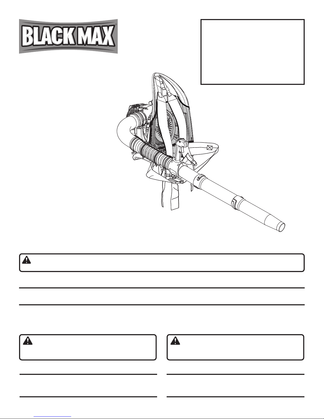
BACKPACK BLOWER
Soufflante dorsale
Sopladora de mochila
BM08570
To register your Black Max
product, please visit:
www.blackmaxtools.com
Pour enregistrer votre produit de
Black Max, s’il vous plaît la visite:
www.blackmaxtools.com
Para registrar su producto de
Black Max, por favor visita:
www.blackmaxtools.com

ii
See this fold-out section for all of the figures referenced in the
operator’s manual.
Consulter l’encart à volets afin d’examiner toutes les figures
mentionnées dans le manuel d’utilisation.
Consulte esta sección desplegable para ver todas las figuras a
las que se hace referencia en el manual del operador.
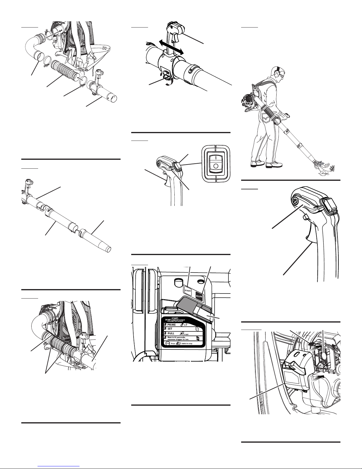
Fig. 1
A - Tube clamp(s) [collier(s) de tuyau,
abrazadera(s) del tubo]
B - Throttle control handle (poignée de
commande d’acélérateur, mango de control
del acelerador)
C - Bellows (soufflet, tubo flexible)
D - Cable tie (serre-câble, amarra del cable)
E - Elbow (coude, codo)
F - Engine (moteur, motor)
A
b
c
d
e
F
G
H
I
J
K
L
M
N
G - Harness height adjustments (réglage de
hauteur du harnais, ajustes de altura del
arnés)
H - Shoulder strap (sangles du harnais, coreas
del arnés)
I - Mesh backing (doublure maillée, espaldar de
malla)
J - Engine switch (comutateur de moteur,
interruptor del motor)
O
K - Straight tube (tube droit, tubo recto)
L - Nozzle (embout, boquilla)
M-
Waist strap (sangle de ceinture, correas de la
cintura)
N - Throttle trigger (gâchette d’accélérateur,
gatillo del acelerador)
O - Throttle control handletube (tubedecomande
d’acélérateur, tubo del mango de control del
acelerador)
iii
prOper OperAtING pOsItION
pOsItION d’UtILIsAtION cOrrecte
pOsIcIóN cOrrectA pArA
eL MANeJO de LA HerrAMIeNtA
Fig. 2
Fig. 3
Fig. 4
A - Elbow tube (coude, tubo de codo)
B - Bellows (soufflet, tubo flexible)
C - Tube clamp(s) [collier(s) de tuyau,
abrazadera(s) del tubo]
D - Throttle control handletube (tubedecomande
d’acélérateur, tubo del mango de control del
acelerador)
A - Throttlecontrolhandletube(tubedecomande
d’acélérateur, tubo del mango de control del
acelerador)
B - Straight tube (tube droit, tubo recto
C - Nozzle (embout, boquilla)
A - Throttle cable (câble d’accélérateur, cable del
acelerador)
B - Cable tie (serre-câble, amarra del cable)
C - Throttlecontrolhandletube(tubedecomande
d’acélérateur, tubo del mango de control del
acelerador)
A- Throttle control handle (poignée de
commande d’acélérateur, mango de control
del acelerador)
B - Locking screw (vis de blocage, tornilo de
seguridad)
Fig. 5
Fig. 6
A - Throttle trigger (gâchette d’accélérateur,
gatillo del acelerador)
B - Engine switch (comutateur de moteur,
interruptor del motor)
C - Cruise control (throttle lock) [régulateur de
vitesse (verrouillage d’accélération), control
de crucero (seguro del acelerador)
Fig. 7
Fig. 8
Fig. 9
A - Cruise control (throttle lock) [régulateur de
vitesse (verrouillage d’accélération), control
de crucero (seguro del acelerador)]
B - Throttle trigger (gâchette d’accélérateur,
gatillo del acelerador)
Fig. 10
A
b
c
d
A
b
c
A
b
c
A
b
A
b
c
A - Startposition(positiondedémarage,posición
de arranque)
B - Run position (position de marche, posición
de funcionamiento)
C - Choke lever (levier de volet de départ, palanca
del anegador)
A
b
A - Air filter (filtre à air, filtro de aire)
B - Knob (bouton, perilla)
C - Air filter cover (couvercle du filtre à air, tapa
del filtro de aire)
A
b
c
c
Ab

2
Introduction ...................................................................................................................................................................... 2
Introduction / Introducción
General Safety Rules........................................................................................................................................................3
Règles de sécurité générales / Reglas de seguridad generales
Specific Safety Rules.....................................................................................................................................................3-4
Règles de sécurité particulières / Reglas de seguridad específicas
Symbols.........................................................................................................................................................................4-5
Symboles / Símbolos
Features............................................................................................................................................................................ 6
Caractéristiques / Características
Assembly.......................................................................................................................................................................6-7
Assemblage / Armado
Operation.......................................................................................................................................................................8-9
Utilisation / Funcionamiento
Maintenance..............................................................................................................................................................10-11
Entretien / Mantenimiento
Accessories .................................................................................................................................................................... 11
Accessoires / Accesorios
Troubleshooting.............................................................................................................................................................. 11
Dépannage / Solución de problemas
Warranty ....................................................................................................................................................................12-14
Garantie / Garantía
Parts Ordering and Service ...............................................................................................................................Back Page
Commande de pièces et réparation / Pedidos de piezas y servicio ......................................................... Page arrière / Pág. posterior
This product has many features for making its use more pleasant and enjoyable. Safety, performance, and dependability
have been given top priority in the design of this product making it easy to maintain and operate.
* * *
Ce produit offre de nombreuses fonctions destinées à rendre son utilisation plus plaisante et satisfaisante. Lors de la
conception de ce produit, l’accent a été mis sur la sécurité, les performances et la fiabilité, afin d’en faire un outil facile à
utiliser et à entretenir.
* * *
Este producto ofrece numerosas características para hacer más agradable y placentero su uso. En el diseño de este producto
se ha conferido prioridad a la seguridad, el desempeño y la fiabilidad, por lo cual se facilita su manejo y mantenimiento.
TABLE OF CONTENTS
TABLE DES MATIÈRES / ÍNDICE DE CONTENIDO
INTRODUCTION
INTRODUCTION / INTRODUCCIÓN

Page 3 — English
WARNING:
Read and understand all instructions. Failure to follow
all instructions listed below may result in electric shock,
fire and/or carbon monoxide poisoning which will cause
death or serious personal injury.
Do not allow children or untrained individuals to use this
unit.
Never start or run the engine inside a closed area; breath-
ing exhaust fumes can kill.
Weareye protectionwhichis marked tocomply withANSI
Z87.1 as well as hearing protection when operating this
equipment.
Keep all bystanders, children, and pets at least 50 feet
away.
Wear heavy long pants, long sleeves, boots, and gloves.
Do not wear loose fitting clothing, short pants, jewelry of
any kind, or go barefoot.
To reduce the risk of injury associated with objects being
drawn into rotating parts, do not wear loose clothing,
scarves, neck chains, and the like. Secure long hair so it
is above shoulder level to prevent entanglement in any
rotating parts.
Do not operate this unit when you are tired, ill, or under
the influence of alcohol, drugs, or medication.
Do not operate in poor lighting.
Keep all parts of your body away from any moving parts
and all hot surfaces of the unit.
Wear a face filter mask in dusty conditions to reduce the
risk of injury associated with the inhalation of dust.
Check the work area before each use. Remove all objects
such as rocks, broken glass, nails, wire, or string which
can be thrown or become entangled in the machine.
Keep firm footing and balance. Do not overreach. Over-
reaching can result in loss of balance or exposure to hot
surfaces.
Never operate the unit without a spark arrestor screen;
this screen is located inside the muffler.
Product users on United States Forest Service land, and
in some states, must comply with fire prevention regu-
lations. This product is equipped with a spark arrestor;
however, other user requirements may apply. Check with
the federal, state, or local authorities in your area.
Before storing, allow the engine to cool.
Use only Black Max replacement parts and accessories.
Failure to do so may cause poor performance or possible
injury.
Maintain the unit per maintenance instructions in this
operator’s manual.
Inspect the unit before each use for loose fasteners, fuel
leaks, etc. Replace damaged parts.
SERVICE
Before cleaning, repairing, or inspecting, shut off the
engine and make certain all moving parts have stopped.
Disconnect the spark plug wire, and keep the wire away
from the plug to prevent starting.
Service on the blower must be performed by qualified
repair personnel only. Service or maintenance performed
by unqualified personnel could result in injury to the user
or damage to the product.
Use only identical replacement parts when servicing the
blower. Use of unauthorized parts may create a risk of
serious injury to the user, or damage to the product.
GENERAL SAFETY RULES
SPECIFIC SAFETY RULES
To reduce the risk of hearing loss associated with sound
level(s), hearing protection is required.
To reduce the risk of injury associated with contacting
rotating parts, stop the engine before installing or
removing attachments. Do not operate without guard(s)
in place. Always disconnect the spark plug before
performing maintenance or accessing any movable
parts.
Do not point the blower nozzle in the direction of people
or pets.
Never run the unit without the blower tubes installed.
Never place objects inside the blower tubes.
Never use for spreading chemicals, fertilizers, toxic sub-
stances, or any other hazardous chemical.
Always hold the blower in your right hand. Refer to the
OPERATION section later in this manual for additional
information.
REFUELING
Fuel is highly flammable. Take precautions when using
to reduce the chance of serious personal injury.
Empty fuel tank and restrain the unit from moving before
transporting in a vehicle.
To reduce the risk of fire and burn injury, handle fuel with
care. It is highly flammable.
Do not smoke while handling fuel.
Mix and store fuel in a container approved for gasoline.

Page 4 — English
Mix fuel outdoors where there are no sparks or flames.
Select bare ground, stop engine, and allow to cool before
refueling.
Loosen fuel cap slowly to release pressure and to keep
fuel from escaping around the cap.
Tighten the fuel cap securely after refueling.
Wipe spilled fuel from the unit. Move 30 feet away from
refueling site before starting engine.
Never attempt to burn off spilled fuel under any circum-
stances.
Store fuel in a cool, well-ventilated area, safely away from
spark and/or flame-producing equipment.
Store fuel in containers specifically designed for this
purpose.
Only refuel outdoors and do not smoke while refueling.
Add fuel before starting the engine. Never remove the cap
of the fuel tank or add fuel while the engine is running or
when the engine is hot.
If fuel is spilled, do not attempt to start the engine but
move the machine away from the area of spillage and
avoid creating any source of ignition until fuel vapors
have dissipated.
Replace all fuel tank and container caps securely.
When draining the fuel tank, use an approved fuel storage
container while in a well-ventilated area.
Save these instructions. Refer to them frequently and use
them to instruct others who may use this product. If you
loan someone this product, loan them these instructions
also.
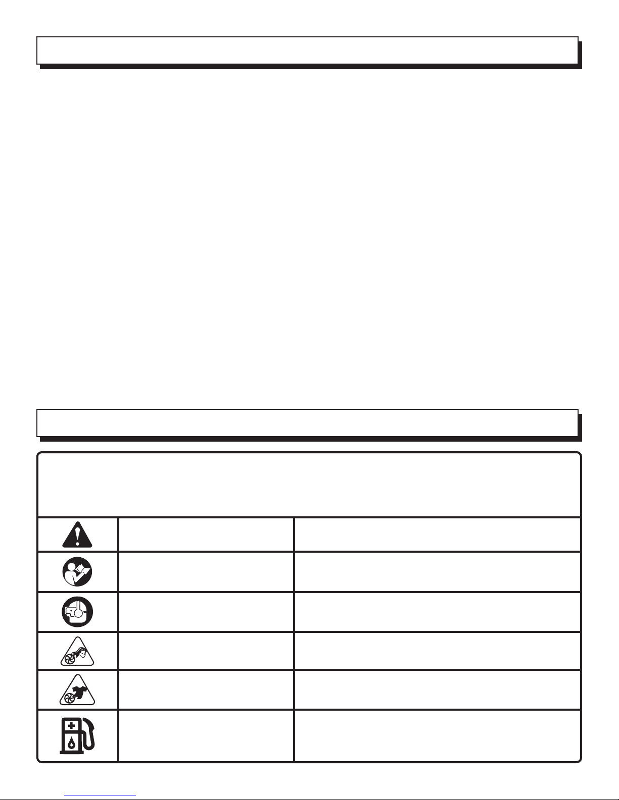
Some of the following symbols may be used on this product. Please study them and learn their meaning. Proper
interpretation of these symbols will allow you to operate the product better and safer.
SYMBOL NAME EXPLANATION
Safety Alert Symbol Precautions that involve your safety.
Read the Operator’s Manual To reduce the risk of injury, user must read and understand
operator’s manual before using this product.
Wear Eye and Hearing Protection
Wear eye protection which is marked to comply with ANSI
Z87.1 as well as hearing protection when operating this
equipment.
Long Hair Risk of long hair being drawn into air inlet.
Loose Clothing Risk of loose clothing being drawn into air intake.
Gasoline and Lubricant
Use unleaded gasoline intended for motor vehicle use with
an octane rating of 87 [(R + M) / 2] or higher. This product
is powered by a 2-cycle engine and requires pre-mixing
gasoline and 2-cycle lubricant.
SPECIFIC SAFETY RULES
SYMBOLS

Page 5 — English
SERVICE
Servicing requires extreme care and knowledge and should
be performed only by a qualified service technician. For
service we suggest you return the product to your nearest
AUTHORIZED SERVICE CENTER for repair. When servic-
ing, use only identical replacement parts.
WARNING:
SAVE THESE INSTRUCTIONS
WARNING:
To avoid serious personal injury, do not attempt to use this
product until you read thoroughly and understand com-
pletely the operator’s manual. If you do not understand
the warnings and instructions in the operator’s manual,
do not use this product. Call Black Max customer service
for assistance.
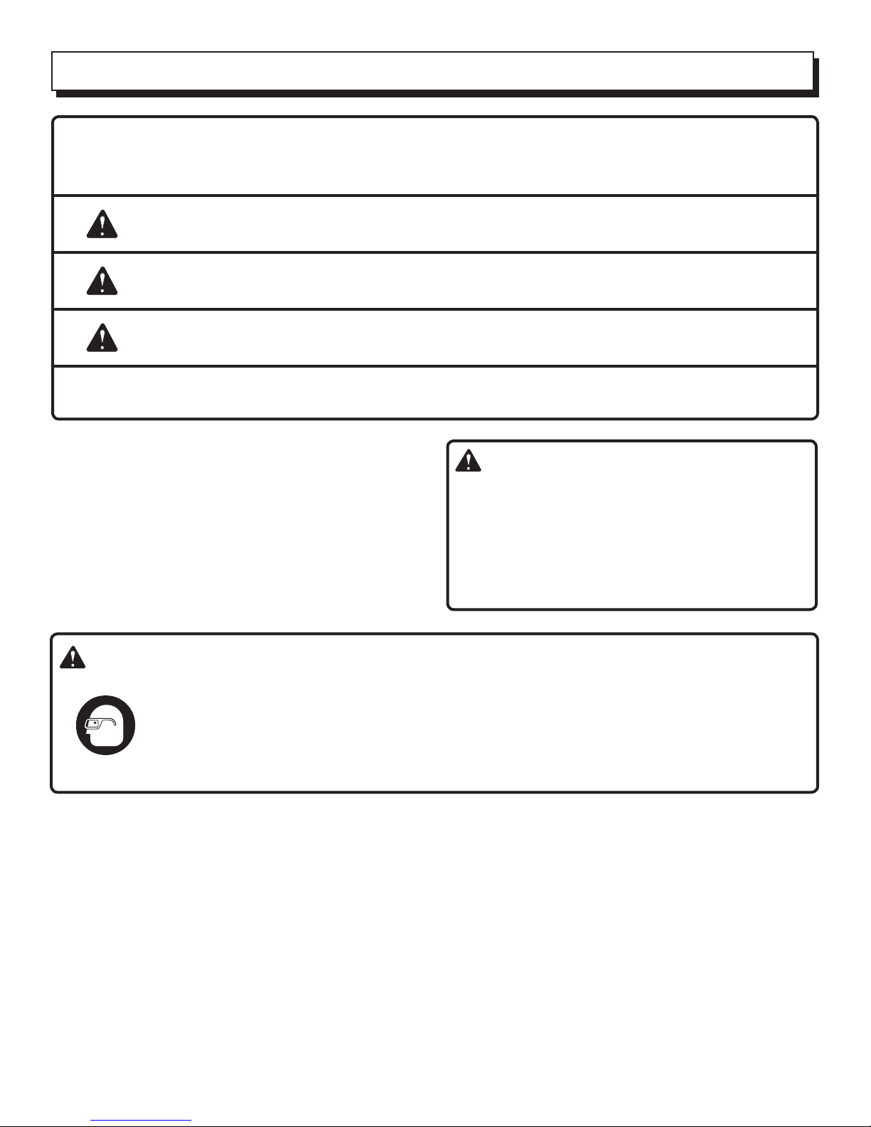
The operation of any power tool can result in foreign objects being thrown into your eyes, which can re-
sult in severe eye damage. Before beginning power tool operation, always wear safety goggles or safety
glasses with side shields and, when needed, a full face shield. We recommend Wide Vision Safety Mask
for use over eyeglasses or standard safety glasses with side shields. Always use eye protection which is
marked to comply with ANSI Z87.1.
The following signal words and meanings are intended to explain the levels of risk associated with this product.
SYMBOL SIGNAL MEANING
DANGER: Indicates an imminently hazardous situation, which, if not avoided, will result
in death or serious injury.
WARNING: Indicates a potentially hazardous situation, which, if not avoided, could result
in death or serious injury.
CAUTION: Indicates a potentially hazardous situation, which, if not avoided, may result in
minor or moderate injury.
CAUTION: (Without Safety Alert Symbol) Indicates a situation that may result in property
damage.
SYMBOLS
Page 6 — English
PRODUCT SPECIFICATIONS
Weight .......................................................................................................................................................................14.5 lbs.
Engine displacement....................................................................................................................................................25.4cc
Air Velocity:
MPH...............................................................................................................................................................................160
CFM ...............................................................................................................................................................................375
FEATURES
KNOW YOUR BLOWER
See Figure 1.
The safe use of this product requires an understanding of
the information on the tool and in this operator’s manual as
well as a knowledge of the project you are attempting. Before
use of this product, familiarize yourself with all operating
features and safety rules.
ADJUSTABLE HARNESS AND WAIST STRAPS
The blower comes with fully adjustable harness and waist
straps to ensure user comfort and ease of operation.
ADJUSTABLE THROTTLE CONTROL HANDLE
Easily adjust throttle control handle by loosening handle
knob to position handle in desired location.
CRUISE CONTROL/THROTTLE LOCK
The cruise control (throttle lock) feature allows the user to
operate the blower without holding the throttle trigger.
MESH BACKING
The blower comes equipped with a mesh backing which
aids in user comfort.
ENGINE
The blower has a powerful 25.4cc engine with sufficient
power to handle tough jobs.
THROTTLE TRIGGER
The blower can be operated at any speed between idle and
full throttle.
ASSEMBLY
UNPACKING
This product requires assembly.
Carefully remove the product and any accessories from
the box. Make sure that all items listed in the packing list
are included.
Inspect the product carefully to make sure no breakage
or damage occurred during shipping.
Do not discard the packing material until you have care-
fully inspected and satisfactorily operated the product.
If any parts are damaged or missing, please call
1-800-726-5760 for assistance.
PACKING LIST
Backpack Blower
Bellows
Cable Tie (2)
Clamp Screws (3)
Elbow
Nozzle
Straight Tube
Tube Clamp (3)
Throttle Control Handle Tube
2-Cycle Engine Lubricant
Operator’s Manual
NOTE: Read and remove all hang tags and store with your
operator’s manual.
WARNING:
If any parts are damaged or missing do not operate
this product until the parts are replaced. Failure to heed
this warning could result in serious personal injury.
WARNING:
Do not attempt to modify this product or create accesso-
ries not recommended for use with this product. Any such
alteration or modification is misuse and could result in a
hazardous condition leading to possible serious personal
injury.
WARNING:
To prevent accidental starting that could cause serious
personal injury, always disconnect the engine spark plug
wire from the spark plug when assembling parts.

Page 7 — English
WARNING:
Disconnect the spark plug wire before assembling parts.
Failure to do so could result in possible serious personal
injury.
ASSEMBLING THE BLOWER TUBES
See Figures 2 - 4.
Place a tube clamp on blower past the raised tabs.
Assemble the elbow tube onto blower by aligning raised
tabs on blower with slots on elbow. Tighten tube clamp
onto elbow.
Attach bellows onto elbow tube by placing a tube clamp
on one end of the bellows then press bellows onto elbow
tube. Tighten tube clamp.
Place a tube clamp on other end of bellows. Press bellows
onto throttle control handle tube. Tighten tube clamp.
NOTE: The position of the throttle control handle may be
adjusted for comfort after the blower is strapped onto the
operator’s back.
Join the straight tube and nozzle together by aligning
raised locking tabs on straight tube with the raised locking
slots on nozzle and twist to secure.
Assemble the connected lower tubes to the throttle
control handle tube by aligning raised locking tabs on
the throttle control handle tube with the raised locking
slots on connected lower tubes by twisting to secure.
NOTE: Check all locking connections after initial run to
ensure they are tightly secured.
Hold the throttle cable against the bellows and install the
cable ties. Cable ties should be tight enough to retain
the throttle cable to the bellows but still allow for move-
ment.
ASSEMBLY
CAUTION:
Make all adjustments to the harness straps before start-
ing the blower to avoid the possibility of injury.
ADJUSTING HARNESS AND WAIST STRAPS
Straps should be adjusted to a comfortable position before
starting the blower.
To adjust harness strap assembly:
Blower should be in operating position before adjusting
the harness straps. Slip arm through harness strap and
onto shoulder, then repeat for the other shoulder.
There are three possible height adjustment positions that
can be used to easily adjust harness.
Slip top buckle of harness from adjustment slot and
position to desired height location.
Tighten (pull down on strap) or loosen (lift up on tab of
strap buckle) each harness strap as needed, until each
is adjusted to a comfortable operating position.
Chest strap should be tightened or loosened until adjusted
to a comfortable operating position.
To adjust waist strap assembly:
Waist strap should be tightened or loosened until adjusted
to a comfortable operating position.
ADJUSTING THROTTLE CONTROL HANDLE
See Figure 5.
Loosen throttle control handle locking screw by twisting
counterclockwise.
Move throttle control handle to desired position and
secure locking screw by twisting clockwise.

Page 8 — English
WARNING:
Do not allow familiarity with this product to make you
careless. Remember that a careless fraction of a second is
sufficient to inflict serious injury.
WARNING:
Always wear safety goggles or safety glasses with side
shields when operating power tools. Failure to do so
could result in objects being thrown into your eyes
resulting in possible serious injury.
APPLICATIONS
You may use this product for the purposes listed below:
Clear leaves and other debris from your lawn
Keep decks and driveways free from leaves and pine
needles
WARNING:
Use extreme caution when handling gasoline and keep
away from all sparks and open flames. Gasoline is
extremely flammable and explosive. A fire or explosion
from gasoline will burn you and others.
MIXING THE FUEL
This product is powered by a 2-cycle engine and requires
pre-mixing gasoline and 2-cycle lubricant. The mixture
should be at a 50:1 ratio, using Black Max Premium 2-Cycle
Small Engine Lubricant. If Black Max Premium 2-Cycle
Small Engine Lubricant is not available, use a high quality
synthetic 2-cycle engine lubricant, mixed at a 50:1 ratio. See
chart later in this section.
To mix the fuel:
Use a clean container that is approved for use with gaso-
line.
Mix the engine lubricant with unleaded gasoline in the
container, according to the instructions on the lubricant
package.
NOTE: This engine is certified to operate on unleaded gaso-
line intended for automotive use with an octane rating of 87
[(R + M) / 2] or higher. Do not use automotive lubricant or
2-cycle outboard lubricant.
NOTE: The fuel mixture will stay fresh up to 30 days. DO NOT
mix quantities larger than usable in a 30 day period.
PREMIUM 2-CYCLE SMALL ENGINE
LUBRICANT (50:1)
GASOLINE LUBRICANT
1 gallon (US) 2.6 oz.
1 liter 20 cc (20 ml)
OPERATION
FILLING THE TANK
WARNING:
Always stop the engine before filling the fuel tank. Never
add fuel to a machine with a running or hot engine. Move
atleast30 ft.fromtherefuelingareabeforestartingengine.
Do not smoke while filling the tank.
Clean the surface around the fuel cap to prevent contami-
nation.
Loosen the fuel cap slowly, by turning it counter-
clockwise.
Pour the fuel mixture carefully into the tank.
Clean and inspect the fuel cap gasket before replacing
the fuel cap.
Replace the fuel cap and tighten it by turning it clock-
wise.
Wipe spilled fuel from the product.
Move at least 30 ft. away from refueling area before start-
ing the product.
WARNING:
Check for fuel leaks. If you find any leaks, correct the
problem before using the product.
WARNING:
A leaking fuel cap is a fire hazard and must be replaced
immediately.
STARTING AND STOPPING
See Figures 6 - 7.
NOTE: It is normal for smoke to be emitted from a new
engine during first use.
To start an engine that is cold or has run dry:
Fill the fuel tank, if necessary. Always use the proper
lubricant/gasoline mixture. See Mixing the Fuel on
page 10.
Disengage the cruise control lever.
NOTE: Do not engage the throttle trigger during the
starting process.
Slowly push the primer bulb seven times.

Page 9 — English
Set the choke lever to the START position.
NOTE: If restarting a warm engine, leave the choke lever
in the RUN position.
Pull the starter cord until the engine runs.
Return the starter cord gently to the starter housing. Do
not allow the rope to snap back.
Allow the engine to run for 15 seconds to warm up before
using.
Engage the throttle trigger to operate.
To stop the blower:
Release the throttle trigger.
Press and hold the engine switch to the “O” or STOP posi-
tion.
To remove blower:
Move harness straps off the shoulders. Let straps slide
down arms.
Grasp the straps and lower the blower to the ground.
WARNING
Keep away from all hot surfaces of the blower. Failure to
do so could result in possible serious personal injury.
OPERATING THE BLOWER
See Figure 8.
Start the blower. Refer to Starting and Stopping earlier
in this manual. Slip arm through harness strap and onto
shoulder, then repeat for the other shoulder. Adjust the
straps to a comfortable position. Refer to Adjusting Har-
ness and Waist Straps earlier in this manual. Operate
the blower from the right side as shown in illustration.
To keep from scattering debris, blow around the outer
edges of a debris pile. Never blow directly into the center
of a pile.
OPERATION
Operatepowerequipmentatreasonablehoursonly−not
early in the morning or late at night when people might
be disturbed. Comply with the times listed in local ordi-
nances.
To reduce sound levels, limit the number of pieces of
equipment used at any one time.
Operate blower at the lowest possible throttle speed to
do the job.
Conserve water by using power blowers instead of hoses
for many lawn and garden applications, including areas
such as gutters, screens, patios, grills, porches, and
gardens.
Check your equipment before operation, especially the
muffler, air intakes, and air filters.
Use rakes and brooms to loosen debris before blowing.
In dusty conditions, slightly dampen surfaces when water
is available.
Watch out for children, pets, open windows or freshly
washed cars, and blow debris safely away.
Use the nozzle for larger volume, so the air stream can
work close to the ground.
After using blowers or other equipment, CLEAN UP!
Dispose of debris properly.
CRUISE CONTROL/THROTTLE LOCK
See Figure 9.
The cruise control (throttle lock) can be used to operate the
blower without holding the throttle trigger.
To engage the cruise control/throttle lock:
Pull cruise control lever back toward user, and stop at
the desired throttle setting.
To release the cruise control, push cruise control lever all
the way toward the front of unit.

Page 10 — English
WARNING:
When servicing, use only identical replacement parts.
Use of any other parts may create a hazard or cause
product damage.
WARNING:
Always wear safety goggles or safety glasses with side
shields during power tool operation or when blowing
dust. If operation is dusty, also wear a dust mask.
WARNING:
Before inspecting, cleaning, or servicing the machine,
shut off engine, wait for all moving parts to stop, and
disconnect spark plug wire and move it away from spark
plug. Failure to follow these instructions can result in
serious personal injury or property damage.
GENERAL MAINTENANCE
Avoid using solvents when cleaning plastic parts. Most
plastics are susceptible to damage from various types of
commercial solvents and may be damaged by their use. Use
clean cloths to remove dirt, dust, lubricant, grease, etc.
WARNING:
Do not at any time let brake fluids, gasoline, petroleum-
based products, penetrating lubricants, etc., come in con-
tact with plastic parts. Chemicals can damage, weaken or
destroy plastic which may result in serious personal
injury.
Only the parts shown on the parts list are intended to be
repaired or replaced by the customer. All other parts should
be replaced at an Authorized Service Center.
REPLACING AND CLEANING AIR FILTER
See Figure 10.
A wet or dirty air filter can affect the way the engine starts,
performs, and wears. The air filter should be checked and
cleaned after 8 hours of operation. If working in dusty soil,
check the air filter after each refueling.
For best performance, the air filter should be replaced once
each year.
To clean the air filter:
Loosen the knob on the air filter cover.
Remove the cover.
Lift the edge of the air filter carefully and peel it out.
Wash the air filter with warm, soapy water.
Rinse and squeeze to dry.
Reinstall the air filter.
NOTE: Make sure the filter is seated properly inside the
cover. Installing the filter incorrectly will allow dirt to enter
the engine, causing rapid engine wear.
Reinstall the cover.
Tighten knob to secure.
SPARK ARRESTOR
The muffler is equipped with a spark arrestor screen inside
muffler body. After extended use the screen can become
dirty and the screen may need to be replaced by an autho-
rized servicing dealer.
WARNING:
To avoid a fire hazard, never run the blower without the
spark arrestor in place.
CLEANING THE EXHAUST PORT AND
MUFFLER
Depending on the type of fuel used, the type and amount of
lubricant used, and/or your operating conditions, the exhaust
port, muffler, and/or spark arrestor screen may become
blocked with carbon deposits. If you notice a power loss
with your gas powered tool, you may need to remove these
deposits to restore performance. We highly recommend that
only qualified service technicians perform this service.
FUEL CAP
The fuel cap contains a non-serviceable filter and a check
valve. A clogged fuel filter will cause poor engine per-
formance. If performance improves when the fuel cap is
loosened, the check valve may be faulty or filter clogged.
Replace the fuel cap if required.
WARNING:
A leaking fuel cap is a fire hazard and must be replaced
immediately.
SPARK PLUG
This engine uses a Champion RCJ6Y with 0.63 mm
(0.025 in.) electrode gap. Use an exact replacement and
replace annually.
STORING THE PRODUCT
Clean all foreign material from the product. Store it in a
well-ventilatedplace that isinaccessible tochildren.Keep
away from corrosive agents such as garden chemicals
and de-icing salts.
MAINTENANCE
Page 11 — English
Abide by all Federal and local regulations for the safe
storage and handling of gasoline.
WHEN STORING 1 MONTH OR LONGER:
Drain all fuel from tank into a container approved for
gasoline. Run engine until it stops.
MAINTENANCE
IF THESE SOLUTIONS DO NOT SOLVE THE PROBLEM, CONTACT YOUR AUTHORIZED SERVICING DEALER.
PROBLEM CAUSE REMEDY
Engine fails to start No fuel in tank
Spark plug shorted or fouled
Spark plug is broken (cracked
porcelain or electrodes broken)
Ignition lead wire shorted, broken, or
disconnected from spark plug
Ignition inoperative
Fill tank.
Replace spark plug.
Replace spark plug.
Replace lead wire or attach to spark
plug.
Contact authorized service center.
Engine hard to start Water in gasoline or stale fuel mixture
Too much lubricant in fuel mixture
Engine is under or over choked
Weak spark at spark plug
Drain entire system and refill with fresh
fuel.
Drain and refill with correct mixture.
Adjust choke as necessary.
Contact authorized service center.
Engine lacks power Air filter clogged Clean or replace air filter.
Engine overheats Insufficient lubricant in fuel mixture Mix fuel as described in starting
instructions.
Look for these accessories at the service center:
ACCESSORIES
Air Filter .........................................Power Care - AP04107
Spark Plug...........................................Champion - RCJ6Y
Fuel Cap .............................................................. AP04108
2-Cycle Lubricant............... (2.6 FL. OZ - 76 ml) AR99G01
WARNING:
Current attachments and accessories available for
use with this product are listed. Do not use any
attachments or accessories not recommended by the
manufacturer of this product. The use of attachments
or accessories not recommended can result in serious
personal injury.
ACCESSORIES
TROUBLESHOOTING

Page 12 — English
LIMITED WARRANTY STATEMENT
OWTIndustries,Inc.,warrantstotheoriginalretailpurchaser
that this Black Max brand outdoor product is free from
defect in material and workmanship and agrees to repair or
replace, at OWT Industries, Inc.’s, discretion, any defective
product free of charge within these time periods from the
date of purchase.
Two years if the product is used for personal, family or
household use;
90 days, if used for any other purpose, such as
commercial or rental.
This warranty extends to the original retail purchaser
only and commences on the date of the original retail
purchase.
Any part of this product found in the reasonable judgment
of OWT Industries, Inc. to be defective in material or
workmanship will be repaired or replaced without charge
for parts and labor by an authorized service center for
Black Max brand outdoor products (Authorized Black Max
Service Center).
Theproduct,includinganydefectivepart,mustbe returned
to an authorized Black Max service center within the
warranty period. The expense of delivering the product to
the service center for warranty work and the expense of
returningitbacktotheownerafterrepairorreplacementwill
be paid by the owner. OWT Industries, Inc.’s, responsibility
inrespect to claims islimited tomaking the requiredrepairs
or replacements and no claim of breach of warranty shall
be cause for cancellation or rescission of the contract of
sale of any Black Max brand outdoor product. Proof of
purchase will be required by the dealer to substantiate
any warranty claim. All warranty work must be performed
by an authorized service dealer.
This warranty is limited to ninety (90) days from the date of
original retail purchase for any Black Max brand outdoor
product that is used for rental or commercial purposes, or
any other income-producing purpose.
This warranty does not cover any product that has been
subject to misuse, neglect, negligence, or accident, or that
has been operated in any way contrary to the operating
instructions as specified in this operator’s manual. This
warranty does not apply to any damage to the product that
is the result of improper maintenance or to any product
that has been altered or modified. The warranty does not
extend to repairs made necessary by normal wear or by the
use of parts or accessories which are either incompatible
with the Black Max brand outdoor product or adversely
affect its operation, performance, or durability. In addition,
this warranty does not cover:
A. Tune-ups – Spark Plugs, Carburetor, Carburetor
Adjustments, Ignition, Filters
B. Wear items – Bump Knobs, Outer Spools, Cutting
Lines, Inner Reels, Starter Pulleys, Starter Ropes, Drive
Belts, Tines, Felt Washers, Hitch Pins, Mulching Blades,
Blower Fans, Blower and Vacuum Tubes, Vacuum Bag
and Straps, Guide Bars, Saw Chains
OWTIndustries,Inc.,reservestherighttochangeorimprove
thedesign ofany Black Maxbrandoutdoorproductwithout
assuming any obligation to modify any product previously
manufactured.
ALL IMPLIED WARRANTIES ARE LIMITED IN DURATION
TO THE STATED WARRANTY PERIOD. ACCORDINGLY,
ANY SUCH IMPLIED WARRANTIES INCLUDING
MERCHANTABILITY, FITNESS FOR A PARTICULAR
PURPOSE, OR OTHERWISE, ARE DISCLAIMED IN THEIR
ENTIRETYAFTERTHEEXPIRATIONOFTHEAPPROPRIATE
TWO-YEAR, ONE-YEAR, OR NINETY-DAY WARRANTY
PERIOD.OWTINDUSTRIES, INC.’S,OBLIGATIONUNDER
THIS WARRANTY IS STRICTLY AND EXCLUSIVELY
LIMITED TO THE REPAIR OR REPLACEMENT OF
DEFECTIVE PARTS AND OWT INDUSTRIES, INC., DOES
NOT ASSUME OR AUTHORIZE ANYONE TO ASSUME
FORTHEM ANYOTHEROBLIGATION.SOME STATESDO
NOT ALLOW LIMITATIONS ON HOW LONG AN IMPLIED
WARRANTYLASTS,SOTHEABOVELIMITATIONMAYNOT
APPLY TO YOU. OWT INDUSTRIES, INC., ASSUMES NO
RESPONSIBILITY FOR INCIDENTAL, CONSEQUENTIAL,
OR OTHER DAMAGES INCLUDING, BUT NOT LIMITED
TO, EXPENSE OF RETURNING THE PRODUCT TO AN
AUTHORIZED BLACK MAX SERVICE CENTER AND
EXPENSE OF DELIVERING IT BACK TO THE OWNER,
MECHANIC’STRAVELTIME,TELEPHONEORTELEGRAM
CHARGES, RENTAL OF A LIKE PRODUCT DURING THE
TIME WARRANTY SERVICE IS BEING PERFORMED,
TRAVEL, LOSS OR DAMAGE TO PERSONAL PROPERTY,
LOSS OF REVENUE, LOSS OF USE OF THE PRODUCT,
LOSS OF TIME, OR INCONVENIENCE. SOME STATES
DO NOT ALLOW THE EXCLUSION OR LIMITATION OF
INCIDENTAL OR CONSEQUENTIAL DAMAGES, SO THE
ABOVE LIMITATION OR EXCLUSION MAY NOT APPLY
TO YOU.
This warranty gives you specific legal rights, and you may
also have other rights which vary from state to state.
This warranty applies to all Black Max brand outdoor
products manufactured by or for OWT Industries, Inc.,
and sold in the United States and Canada.
To locate your nearest Authorized Black Max Service
Center, dial 1-800-726-5760.
WARRANTY

Page 13 — English
THE FOLLOWING CALIFORNIA AIR RESOURCES BOARD (CARB) STATEMENT ONLY APPLIES TO MODEL NUMBERS
REQUIRED TO MEET THE CARB REQUIREMENTS.
The U.S. Environmental Protection Agency (EPA), the California Air Resources Board
(CARB), and OWT Industries, Inc., are pleased to explain the Emissions Control
System Warranty on your 2009 model year non-road or small off-road engine. In
California, new equipment that uses small off-road engines must be designed, built,
and equipped to meet the state’s stringent anti-smog standards. In other states, new
2000 and later model year non-road engines must be designed, built, and equipped
at the time of sale to meet the U.S. EPA regulations for small non-road engines. The
non-road engine must be free from defects in materials and workmanship which
cause it to fail to conform with U.S. EPA standards for the first two years of engine
use from the date of sale to the ultimate purchaser. OWT Industries, Inc., must war-
rant the emission control system on your non-road or small off-road engine for the
period of time listed above provided there has been no abuse, neglect, or improper
maintenance of your non-road or small off-road engine.
Your emission control system may include parts such as the carburetor or fuel injection
system, the ignition system, catalytic converters, fuel tanks, valves, filters, clamps,
connectors, and other associated components. Also included may be hoses, belts
and connectors, and other emission-related assemblies.
Where a warrantable condition exists, OWT Industries, Inc., will repair your non-road or
small off-road engine at no cost to you, including diagnosis, parts, and labor performed
at an authorized service center for Black Max brand outdoor products.
MANUFACTURER’S WARRANTY COVERAGE:
This product’s emissions control system is warranted for two years. If any emission-
related part on your engine is defective, the part will be repaired or replaced by OWT
Industries, Inc., free of charge.
OWNER’S WARRANTY RESPONSIBILITIES
(a) As the non-road or small off-road engine owner, you are responsible for the
performance of the required maintenance listed in your operator’s manual. OWT
Industries, Inc., recommends that you retain all receipts covering maintenance
on your non-road or small off-road engine, but OWT Industries, Inc., cannot deny
warranty solely for the lack of receipts or for your failure to ensure the performance
of all scheduled maintenance. Any replacement part or service that is equiva-
lent in performance and durability may be used in non-warranty maintenance or
repairs, and shall not reduce the warranty obligations of OWT Industries, Inc.
(b) As the non-road or small off-road engine owner, you should be aware, however,
that OWT Industries, Inc., may deny you warranty coverage if your non-road or small
off-road engine or a part has failed due to abuse, neglect, improper maintenance,
or unapproved modifications.
(c) You are responsible for presenting your non-road or small off-road engine to an
authorized service dealer as soon as a problem exists. The warranty repairs should
be completed in a reasonable amount of time, not to exceed 30 days.
If you have any questions regarding your warranty rights and responsibilities, you
should contact a OWT Industries, Inc., Customer Representative at 1-800-726-
5760.
DEFECT WARRANTY COVERAGE REQUIREMENTS:
(a) The warranty period begins on the date the engine or equipment is delivered to
an ultimate purchaser.
(b) General Emissions Warranty Coverage. OWT Industries, Inc., warrants to the
ultimate purchaser and each subsequent purchaser that your non-road or small off-
road engine is designed, built, and equipped at the time of sale to conform with all
applicable regulations adopted by the California Air Resources Board or the United
States Environmental Protection Agency; and that it is free from defects in materials
and workmanship which cause the engine to fail to conform with applicable regula-
tions for a period of two years from the date the non-road or small off-road engine
is purchased by the initial purchaser.
(c) The warranty on emissions-related parts will be interpreted as follows: Any
warranted part that is not scheduled for replacement as required in the Emissions
Maintenance Schedule and Warranty Parts List set forth below is warranted for two
years. If any such part (including any part that is scheduled only for regular inspec-
tion) fails during the period of warranty coverage, it will be repaired or replaced at
any Black Max Authorized Service Center at no charge. Any such part repaired or
replaced under warranty will be warranted for the remaining warranty period. A
statement to the effect of “repair or replace as necessary” would not reduce the
period of warranty coverage. Any warranted part that is scheduled for replacement
as required maintenance in the Emissions Maintenance Schedule and Warranty Parts
List is warranted for the period of time prior to the first scheduled replacement point
for that part. Any such part repaired or replaced under warranty is warranted for the
remainder of the period prior to the first scheduled replacement point, and will be
repaired or replaced at any Black Max Authorized Service Center for no charge until
that replacement point is reached.
OWT Industries, Inc., shall remedy warranty defects at any authorized Black Max
Authorized Service Center, including any distribution center that may be franchised
to service the subject engines. Any diagnostic work done at a Black Max Authorized
Service Center shall be free of charge to the owner if such work determines that a
warranted part is defective. Any manufacturer-approved or equivalent replacement
part may be used for any warranty maintenance or repairs on emission-related parts,
and must be provided free of charge to the owner if the part is still under warranty.
OWT Industries, Inc., is liable for damages to other engine components caused by
the failure of a warranted part still under warranty.
Add-on or modified parts that are not exempted by the California Air Resource
Board may not be used. The use of any non-exempted add-on or modified parts
will be grounds for disallowing a warranty claim. OWT Industries, Inc., will not be
liable to warrant failures of warranted parts caused by the use of a non-exempted
add-on or modified part.
The California Air Resources Board’s Emission Warranty Parts List specifically
defines the emission-related warranted parts. (EPA’s regulations do not include a
parts list, but the EPA considers emission-related warranted parts to include all the
parts listed below.) OWT Industries, Inc., will provide any documents that describe
its warranty procedures or policies within five days upon request by the California
Air Resources Board.
EMISSIONS PARTS LIST
Emissions parts vary from product to product. Your emissions control system warranty
applies to any of the following components that may be included on your product:
(1) Fuel Metering System
(i) Carburetor and internal parts (and/or pressure regulator or fuel injection
system).
(ii) Air/fuel ratio feedback and control system.
(iii) Cold start enrichment system.
(iv) Fuel Tank.
(2) Air Induction System
(i) Controlled hot air intake system.
(ii) Intake manifold.
(iii) Air filter.
(3) Ignition System
(i) Spark Plugs.
(ii) Magneto or electronic ignition system.
(iii) Spark advance/retard system.
(4) Exhaust Gas Recirculation (EGR) System
(i) EGR valve body and carburetor spacer, if applicable.
(ii) EGR rate feedback and control system.
(5) Air Injection System
(i) Air pump or pulse valve.
(ii) Valves affecting distribution of flow.
(iii) Distribution manifold.
(6) Catalyst or Thermal Reactor System
(i) Catalytic converter.
(ii) Thermal reactor.
(iii) Exhaust manifold.
(7) Particulate Controls
(i) Traps, filters, precipitators, and any other device used to capture particulate
emissions.
(8) Miscellaneous Items Used in Above Systems
(i) Electronic controls.
(ii) Vacuum, temperature, and time sensitive valves and switches.
(iii) Hoses, belts, connectors, and assemblies.
OWT Industries, Inc., will furnish with each new engine written instructions for its
maintenance and use by the owner.
The Emissions Compliance Period referred to on the Emissions Compliance label
indicates the number of operating hours for which the engine has been shown to
meet Federal emission requirements. Category C=50 hours, B=125 hours, and
A=300 hours.
OWT INDUSTRIES, INC., LIMITED WARRANTY STATEMENT FOR FEDERAL AND CALIFORNIA EMISSION CONTROL
SYSTEMS NON-ROAD AND SMALL OFF-ROAD ENGINES
YOUR WARRANTY RIGHTS AND OBLIGATIONS
WARRANTY
Page 14 — English
EMISSIONS MAINTENANCE SCHEDULE AND WARRANTED PARTS LIST
Emissions Parts Inspect Before Clean Every Replace Clean Every Replace Every
Each Use 5 Hours Every 25 Hours 25 Hours 50 Hours
or Yearly or Yearly
CATALYTIC MUFFLER ASSEMBLY ................................................................................................................... X
AIR FILTER ASSY
includes:
Filter ................................................................. X............................. X
SPARK SCREEN ..................................................................................................................X
CARBURETOR ASSY
includes:
Heat Dam
Gaskets
FUEL TANK ASSY
includes:
Fuel Lines........................ X
Fuel Cap.......................... X
Fuel Filter
IGNITION ASSY
includes:
Spark Plug........................................................................................ X
ALL EMISSIONS-RELATED PARTS ARE WARRANTED FOR TWO YEARS OR FOR THE PERIOD OF TIME PRIOR TO
THE PARTS FIRST SCHEDULED REPLACEMENT WHICHEVER COMES FIRST.
THIS PRODUCT WAS MANUFACTURED WITH A CATALYST MUFFLER
Congratulations! You have made an investment toward protecting the environment. In order to maintain this product’s
original emission level, please refer to the maintenance section below.
CALL
1-800-726-5760
www. blackmaxtools.com
CALL US FIRST
For any questions about operating or maintaining your product,
call the Black Max Help Line!
Your product has been fully tested prior to shipment to ensure
your complete satisfaction.
WARRANTY

3 — Français
AVERTISSEMENT :
Lire attentivement toutes les instructions. Le non-
respect de toutes les instructions ci-dessous peut
entraîner un choc électrique, un incendie et / ou une
intoxication par le monoxyde de carbone, ce qui peut
causer des blessures graves voire la mort.
Ne pas laisser des enfants ou personnes n’ayant pas
reçu une formation adéquate utiliser cet outil.
Nejamaislancerou faire tournerlemoteurdansunendroit
clos. Les gaz d’échappement peuvent être mortels.
Porter une protection oculaire certifiée conforme à la
norme ANSI Z87.1, ainsi qu’une protection auditive lors
de l’utilisation de cet outil.
Garder les badauds, enfants et visiteurs à une distance
de 15 m (50 pi).
Porter des pantalons longs, manches longs, des
chaussures de travail et des gants épais. Ne pas porter
de vêtements amples, shorts, bijoux quels qu’ils soient
et ne pas travailler pieds nus.
Pour réduire les risques de happement par les pièces en
mouvement,nepasporterdevêtementsamples,foulards,
colliers ou autres articles de même nature. Attacher
les cheveux longs pour les maintenir au-dessus des
épaules, afin qu’ils ne se prennent pas dans les pièces
en mouvement.
Ne pas utiliser cet outil en état de fatigue, si l’on est
souffrant ou sous l’influence de l’alcool, de drogues ou
de médicaments.
Ne pas travailler sous un éclairage insuffisant.
Garder toutes les parties du corps à l’écart des pièces
en mouvement et des parties brûlantes de l’outil.
Porterunmasquefacialfiltrantdanslesmilieuxpoussiéreux
afin de réduire le risque de lésions lié à l’inhalation de
poussière.
Examiner la zone de travail avant chaque utilisation. La
débarrasser de tous les objets tels que cailloux, verre
brisé, clous, fils métalliques, cordes, etc. risquant d’être
projetés ou de se prendre dans la machine.
Se tenir bien campé et en équilibre. Ne pas travailler
hors de portée. Le travail hors de portée risque de faire
perdre l’équilibre ou de causer un contact avec les pièces
brûlantes.
Ne jamais utiliser l’outil sans le pare-étincelles, qui se
trouve dans le silencieux.
Les produits utilisés sur les territoires des services
forestiers des États-Unis et de certains états doivent être
conformes aux réglementations de lutte contre l’incendie.
Cet outil est doté d’un pare-étincelles, toutefois, d’autres
dispositifs peuvent être requis. Consulter les autorités
locales et gouvernementales.
Laisser le moteur refroidir avant de remiser l’outil.
Utiliserexclusivementdespiècesderechangeetaccessoires
Black Max. Ne pas suivre cette recommandation peut
entraîner un mauvais fonctionnement et des blessures.
Entretenir l’outil conformément aux instructions de ce
manuel d’utilisation.
Inspecterl’outilavantchaqueutilisationpours’assurerqu’il
n’y a pas de pièces desserrées, de fuites de carburant,
etc. Remplacer les pièces endommagées.
DÉPANNAGE
Avant de nettoyer, réparer ou inspecter, arrêter le moteur
et vérifier que toutes les pièces en mouvement sont
immobilisées. Déconnecter le fil de bougie et le garder
à l’écart de la bougie afin d’empêcher un démarrage
accidentel.
Le dépannage de la soufflante doit exclusivement
être confié à un personnel qualifié. Les réparations ou
entretiens par des personnes non qualifiées peuvent
entraîner des blessures ou dommages à l’outil.
Utiliser exclusivement des pièces identiques à celles
d’origine pour les réparations. L’usage de pièces non
autorisées peut présenter des risques de blessures ou
de dommage pour l’outil.
RÈGLES DE SÉCURITÉ GÉNÉRALES
RÈGLES DE SÉCURITÉ PARTICULIÈRES
Pour réduire les risques de perte de l’ouïe causée par le
niveau sonore, porter une protection auditive.
Pour réduire les risques de blessures infligées par des
pièces en rotation, arrêter le moteur avant d’installer ou
de retirer des accessoires. Ne pas utiliser la machine sans
que tous les dispositifs de protection soient en place.
Toujours débrancher le fil de bougie avant de procéder à
un entretien ou d’accéder à des pièces en mouvement.
Ne pas diriger la soufflante vers une personne ou un
animal.
Ne jamais utiliser la soufflante sans les tubes installés.
Ne jamais rien insérer dans les tubes.
Ne jamais utiliser pour répandre des engrais, produits
chimiques, substances toxiques ou autres produits
dangereux.
Toujours tenir la soufflante avec la main droite. Voir
UTILISATION plus loin dans ce manuel, pour des
informations supplémentaires.
4 — Français
Certains des symboles ci-dessous peuvent être présents sur la produit. Veiller à les étudier et à apprendre leur
signification. Une interprétation correcte de ces symboles permettra d’utiliser la produit plus efficacement et de
réduire les risques.
SYMBOLE NOM EXPLICATION
Symbole d’alerte de sécurité Précautions destinées à assurer la sécurité.
Lire le manuel d’utilisation
Pour réduire les risques de blessures, l’utilisateur doit lire
et veiller à bien comprendre le manuel d’utilisation avant
d’utiliser ce produit.
Porter une protection oculaire et
auditive
Porter une protection oculaire certifiée conforme à la
norme ANSI Z87.1, ainsi qu’une protection auditive lors de
l’utilisation de cet outil.
Cheveux longs Risque d’aspiration des cheveux longs dans l’entrée d’air.
Vêtements amples Risque d’aspiration des vêtements amples dans
l’entrée d’air.
Essence et lubrifiant
Utiliser de l’essence sans plomb pour automobiles, avec un
indice d’octane de 87 [(R + M) / 2] ou plus. Cet outil utilise
un moteur deux temps qui nécessite le mélange d’essence
et de lubrifiant 2 temps.
RAVITAILLEMENT EN CARBURANT
Le carburant est extrêmement inflammable. Lors de
l’utilisation, prendre les précautions nécessaires pour
réduire le risque de blessures graves.
Pour le transport dans un véhicule, le réservoir doit être
vide et la machine bien arrimée.
Manipuler le carburant avec précaution pour éviter les
risques d’incendies et de brûlures. Le carburant est
extrêmement inflammable.
Ne pas fumer pendant la manipulation du carburant.
Mélanger et conserver le carburant dans un bidon ou
jerrycan approuvé pour l’essence.
Mélanger le carburant à l’extérieur, loin de toute flamme
ou source d’étincelles.
Poser la machine sur un sol nu, arrêter le moteur et le
laisser refroidir avant de faire le plein.
Desserrer le bouchon du réservoir lentement pour relâcher
la pression et éviter que le carburant s’échappe.
Une fois le réservoir plein, remettre le bouchon en place
et le serrer fermement.
Essuyer tout le carburant éventuellement répandu.
S’éloigner de 9 m (30 pi) du point d’approvisionnement
avant de lancer le moteur.
N’essayer en aucun cas de brûler le carburant répandu.
Conserver le carburant dans une zone froide bien ventilée
à l’écart d’étincelles et / ou de matériels produisant des
flammes.
Conserver le carburant dans des jerrycans spécialement
conçus à cet effet.
Toujours faire le plein à l’extérieur et ne pas fumer pendant
le ravitaillement en carburant.
Faire l’appoint de carburant avant de lancer le moteur.
Ne jamais retirer le couvercle du réservoir de carburant
ni ajouter du carburant pendant que le moteur tourne ou
quand le moteur est chaud.
Si du carburant est répandu, ne pas essayer de lancer le
moteur, mais éloigner la machine et éviter de créer une
source d’inflammation jusqu’à ce que les vapeurs de
carburant se soient dissipées.
Remettre en place tous les bouchons de conteneur et de
réservoir de carburant en les serrant fermement.
Lors de la vidange du réservoir de carburant, utiliser
un bidon ou jerrycan approuvé pour la conservation de
carburant et procéder dans un endroit bien aéré.
Conserver ces instructions. Les consulter fréquemment et
les utiliser pour instruire les autres utilisateurs éventuels.
Si ce produit est prêté, il doit être accompagné de ces
instructions.
RÈGLES DE SÉCURITÉ PARTICULIÈRES
SYMBOLES
5 — Français
DÉPANNAGE
Le dépannage exigeant des précautions extrêmes et la
connaissance du système, il ne doit être confié qu’à un
technicien de service qualifié. En ce qui concerne les
réparations, nous recommandons de confier l’outil au
CENTRE DE RÉPARATIONS AGRÉÉ le plus proche. Utiliser
exclusivement des pièces identiques à celles d’origine pour
les réparations.
AVERTISSEMENT :
CONSERVER CES INSTRUCTIONS
AVERTISSEMENT :
Pour éviter des blessures graves, ne pas essayer
d’utiliser ce produit avant d’avoir lu entièrement et
bien compris toutes les instructions contenues dans le
manuel d’utilisation. Si tous les avertissements et toutes
les consignes de sécurités et instructions du manuel
d’utilisation ne sont pas bien compris, ne pas utiliser ce
produit. Appeler le service après-vente Black Max.
L’utilisation de tout outil motorisé peut entraîner la projection d’objets dans les yeux et causer des
lésions oculaires graves. Lors de l’utilisation d’outils motorisés, toujours porter des lunettes étanches
ou des lunettes de sécurité à coques latérales ou, si nécessaire, un masque facial intégral. Nous
recommandons d’utiliser un masque facial à champ de vision élargi, plutôt que des lunettes de vue
ou des lunettes de sécurité munies d’écrans latéraux. Toujours porter une protection oculaire certifiée
conforme à la norme ANSI Z87.1.
Les termes de mise en garde suivants et leur signification ont pour but d’expliquer le degré de risques associé à l’utilisation
de ce produit.
SYMBOLE SIGNAL SIGNIFICATION
DANGER : Indique une situation extrêmement dangereuse qui, si elle n’est pas évitée,
aura pour conséquences des blessures graves ou mortelles.
AVERTISSEMENT : Indique une situation potentiellement dangereuse qui, si elle n’est pas évitée,
pourrait entraîner des blessures graves ou mortelles.
ATTENTION : Indique une situation potentiellement dangereuse qui, si elle n’est pas évitée,
pourraît entraîner des blessures légères ou de gravité modérée.
ATTENTION : (Sans symbole d’alerte de sécurité) Indique une situation pouvant entraîner
des dommages matériels.
SYMBOLES
6 — Français
FICHE TECHNIQUE
Poids ..............................................................................................................................................................6,6 kg (14,5 lb)
Cylindrée .....................................................................................................................................................................25,4 cc
Vitesse d’air :
Mi/h...............................................................................................................................................................................160
Pi3/min ..........................................................................................................................................................................375
CARACTÉRISTIQUES
APPRENDRE À CONNAÎTRE LA SOUFFLANTE
Voir la figure 1.
La sécurité d’utilisation de ce produit exige la compréhension
des informations apposées sur l’outil et contenues dans ce
manuel d’utilisation, ainsi que la connaissance du travail
à exécuter. Avant d’utiliser ce produit, se familiariser avec
toutes ses fonctions et règles de sécurité.
SANGLES DE HARNAIS ET DE CEINTURE
RÉGLABLES
Un harnais et des sangles de ceintures complètement
réglables sont fournis avec la soufflante pour assurer le
confort et la facilité d’utilisation.
MANETTE DE COMMANDE DES GAZ
RÉGLABLE
Régler aisément la manette de commande des gaz en
desserrant la molette de la manette pour placer cette
dernière à l’emplacement souhaité.
E/VERROUILLAGE D’ACCÉLÉRATION
Le régulateur de vitesse (verrouillage d’accélération)
permet d’utiliser la soufflante sans maintenir le doigt sur la
gâchette.
DOUBLURE MAILLÉE
La soufflante est doté d’une doublure maillée pour le confort
de l’utilisateur.
MOTEUR
Cette soufflante est équipée d’un moteur de 25,4 cc assez
puissant pour s’acquitter des tâches les plus dures.
GÂCHETTE D’ACCÉLÉRATEUR
La soufflante peut être utilisée à n’importe quelle vitesse
entre le ralenti et le régime maximum.
DÉBALLAGE
Ce produit doit être assemblé.
Avec précaution, sortir la produit et les accessoires de la
boîte. S’assurer que toutes les pièces figurant sur la liste
de contrôle sont incluses.
Examiner soigneusement la produit pour s’assurer
que rien n’a été brisé ou endommagé en cours de
transport.
Ne pas jeter les matériaux d’emballage avant d’avoir
soigneusement examiné la produit et avoir vérifié qu’il
fonctionne correctement.
Si des pièces sont manquantes ou endommagées,
appeler le 1-800-726-5760.
LISTE DE CONTRÔLE
Soufflante dorsale Soufflets
Attache (2) Vis de du collier (3)
Coude Embout
Tube droit Collier du tuyau (3)
Tube de commande d’accélérateur
Lubrifiant 2 temps Manuel d’utilisation
NOTE : Lire toutes les étiquettes avant de les retirer et de
les ranger avec le manuel d’utilisation.
AVERTISSEMENT :
Si des pièces manquent ou sont endommagées, ne pas
utiliser ce produit avant qu’elles aient été remplacées.
Le non-respect de cet avertissement pourrait entraîner
des blessures graves.
AVERTISSEMENT :
Ne pas essayer de modifier cet outil ou de créer des
accessoires non recommandés pour ce produit. De telles
altérations ou modifications sont considérées comme un
usage abusif et peuvent créer des conditions dangereuses,
risquant d’entraîner des blessures graves.
AVERTISSEMENT :
Pour empêcher un démarrage accidentel pouvant
entraîner des blessures graves, toujours déconnecter le
fil de bougie de moteur de la bougie d’allumage avant
d’assembler des pièces.
ASSEMBLAGE
Table of contents
Languages:
Other Black Max Blower manuals


Popular Blower manuals by other brands

Black & Decker
Black & Decker GW2600 user manual

Stihl
Stihl BGA 57 instruction manual

CleanCraft
CleanCraft KM 625 operating instructions

Wolf Garten
Wolf Garten LYCOS 40/480 V Original operating instructions

Thermador
Thermador VTD600P installation manual

Scheppach
Scheppach S700 Translation from the original instruction manual


EINHELL
EINHELL PICOBELLA Original operating instructions

Husqvarna
Husqvarna Grass Catcher 2345 XLS Operator and parts manual

Stihl
Stihl SHE 81 instruction manual

Central Machinery
Central Machinery 93245 Assembly and operating instructions

Tanaka
Tanaka THB-260PF Handling instructions

Unitary products group
Unitary products group LA300 installation manual