Black Max BM254BV User manual

R
OPERATOR’S MANUAL
Manual del operador
BLOWER-VAC
Sopladora de mochila
BM254BV
To register your Black Max product,
please visit:
www.blackmaxtools.com
Para registrar su producto de Black
Max, por favor visita:
www.blackmaxtools.com
Su sopladora de mochila ha sido diseñado y fabricado de conformidad con nuestras estrictas normas para brindar
fiabilidad, facilidad de uso y seguridad para el operador. Con el debido cuidado, le brindará muchos años de sólido
funcionamiento y sin problemas.
ADVERTENCIA: Para reducir el riesgo de lesiones, el usuario debe leer y comprender el manual del
operador antes de usar este producto.
SAVE THIS MANUAL FOR FUTURE REFERENCE
GUARDE ESTE MANUAL PARA FUTURAS CONSULTAS
Your blower has been engineered and manufactured to our high standard for dependability, ease of operation, and opera-
tor safety. When properly cared for, it will give you years of rugged, trouble-free performance.
WARNING: To reduce the risk of injury, the user must read and understand the operator’s manual before us-
ing this product.
NOTICE AVISO
Do not use E15 or E85 fuel (or fuel containing greater than 10% ethanol) in this product. It
is a violation of federal law and will damage the unit and void your warranty.
No utilice combustibles E15 o E85 (ni combustibles que contengan más de 10 % de etanol)
con este producto. Esto constituye una violación a la ley federal, dañará la unidad y anulará la garantía.
ii
See this fold-out section for all the figures referenced in the operator’s manual.
Vea esta sección de la página desplegable para todas las figuras mencionó en el manual del operador.
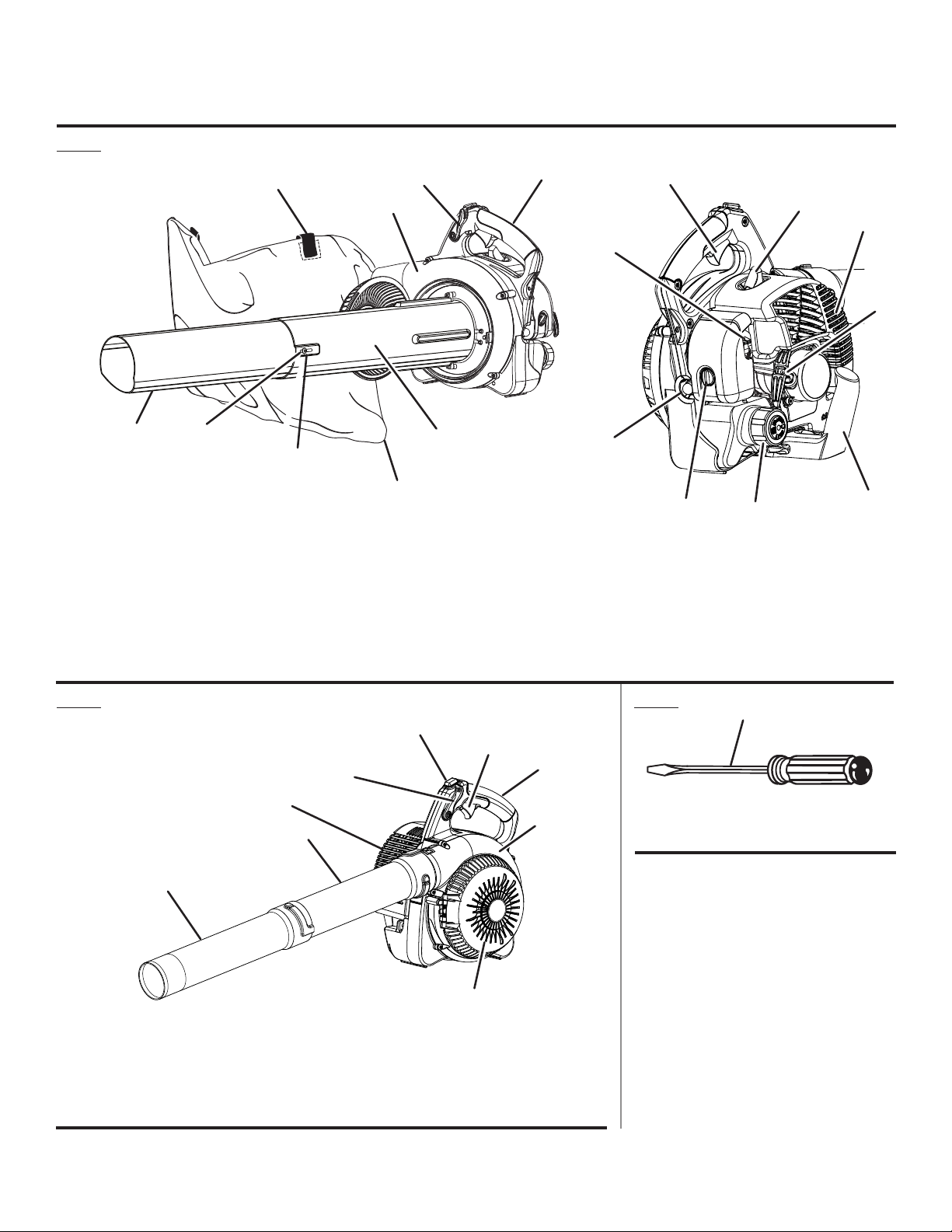
Fig. 1
Fig. 3Fig. 2
A - Raised slot (ranura realzada)
B - Vacuum bag shoulder strap (coreas del
arnés)
C - Throttle lock (seguro del acelerador)
D - Main housing (armazón principal)
E - Upper vacuum tube (tubo superior de la
aspiradora)
F - Vacuum bag (saco de la aspiradora)
A - Stop switch (interruptor del apagado)
B - Throttle trigger (gatillo del acelerador)
C - Throttle lock (seguro del acelerador)
D - Upper handle (mango superior)
E - Main housing (armazón principal)
C
I
A
P
O
G
J
D
F
R
H
K
H
A
B
L
E
A
B
C
F
I
G - Vacuum tube screw (tornilo del tubo de la
aspiradora)
H
- Lower vacuum tube (tubo inferior de la
aspiradora)
I - Spark plug (bujía)
J - Choke lever (palanca del anegador)
K - Throttle trigger (gatillo del acelerador)
L - Muffler (silencieux, silenciador)
M - Upper handle (mango superior)
N - Starter grip and rope (mango del arrancador
con cuerda)
O - Air filter cover knob (perilla del tapa del filtro
de aire)
P - Primer bulb (bomba de cebado)
Q - Vacuum handle (mango de la aspiradora)
R - Fuel cap (tapa de combustible)
A - Flat blade screwdriver (destornillador de
punta plana)
F - Vacuum inlet door (puert a de la entrada)
G - Muffler (silenciador)
H - Upper blower tube (tubo superior de la
sopladora)
I - Sweeper nozzle (boquilla ancha)
M
Q
D
N
G
E

iii
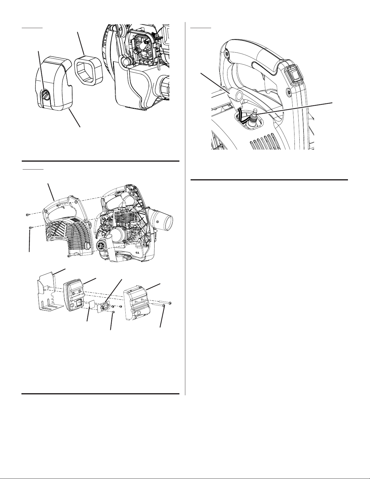
A - Upper handle (mango superior)
B - Recoil housing (etiqueta de alojamiento
retráctil)
C - Grounding tab (lengüeta de conexión a tierra)
D - Grounding wire (cable de conexión a tierra)
E - Vacuum handle (mango de la aspiradora)
F - Vacuum handle knobs (perilas del mango de
la aspiradora)
Fig. 8
A - Vacuum bag (saco de la aspiradora)
B - Adaptor (adaptadores)
A - Upper vacuum tube (tubo superior de la
aspiradora)
B - Inlet door (puert a de la entrada de la
aspiradora)
C - Vacuum opening (abertur a de aspiración)
D - Screw (tornillo)
E - Screw mount (montaje del tornillo)
A - Vacuum bag assembly (conjunto del saco de
la aspiradora)
B - Vacuum door hinge (bisagra de la puerta de la
aspiradora
C - Vacuum inlet door (puerta de la entrada de la
aspiradora)
D - Door tab (orejeta de la puerta)
F
B
C
A
A - Adaptor installed in vacuum bag (adaptador
instalado en el saco de la aspiradora)
B - Main housing outlet (gatillo del acelerador)
C - Raised slot (ranura realzada)
D - Raised locking tab (orejeta realzada de
aseguramiento)
D
Fig. 9
C
A
B
AD
E
B
C
Fig. 6
Fig. 5
Fig. 4
Fig. 7
A - Sweeper nozzle (control de crucero)
B - Raised locking tab (orejeta de seguridad elevada)
C - Upper blower tube (tubo superior de la sopladora)
D - Main housing outlet (salida del alojamiento)
B
D
E
C
B
A
B
D
A
B
B
A
CD

iv
A - Full choke (“Full Choke” [anegación
máxima])
B - Half choke (“Half Choke” [anegación media])
C - Run position (“Run” [funcionamiento])
Fig. 14
A - Throttle lock (seguro del acelerador)
B - Throttle trigger (gatillo del acelerador)
A - Sweeper nozzle (control de crucero)
Fig. 15
Fig. 12
Fig. 11
Fig. 13
FULL
HALF
RUN
FULL
HALF
RUN
FULL
HALF
RUN
PROPER OPERATING POSITION
POSITION D’UTILISATION CORRECTE
PROPER OPERATING POSITION
HOLD MUFFLER AWAY FROM BODY
AND CLOTHING
POSICIÓN CORRECTA
MANTENGA ALEJADO EL SILENCIADOR
DEL CUERPO Y DE LA ROPA
A - Throttle trigger (gatillo del acelerador)
B - Stop switch (interruptor del apagado)
C - Choke lever (bomba de cebado)
D - Starter grip and rope (mango del arrancador
con cuerda)
E - Primer bulb (bomba de cebado)
Fig. 10
A
C
A
B
B
ED
B
C
A
A
v
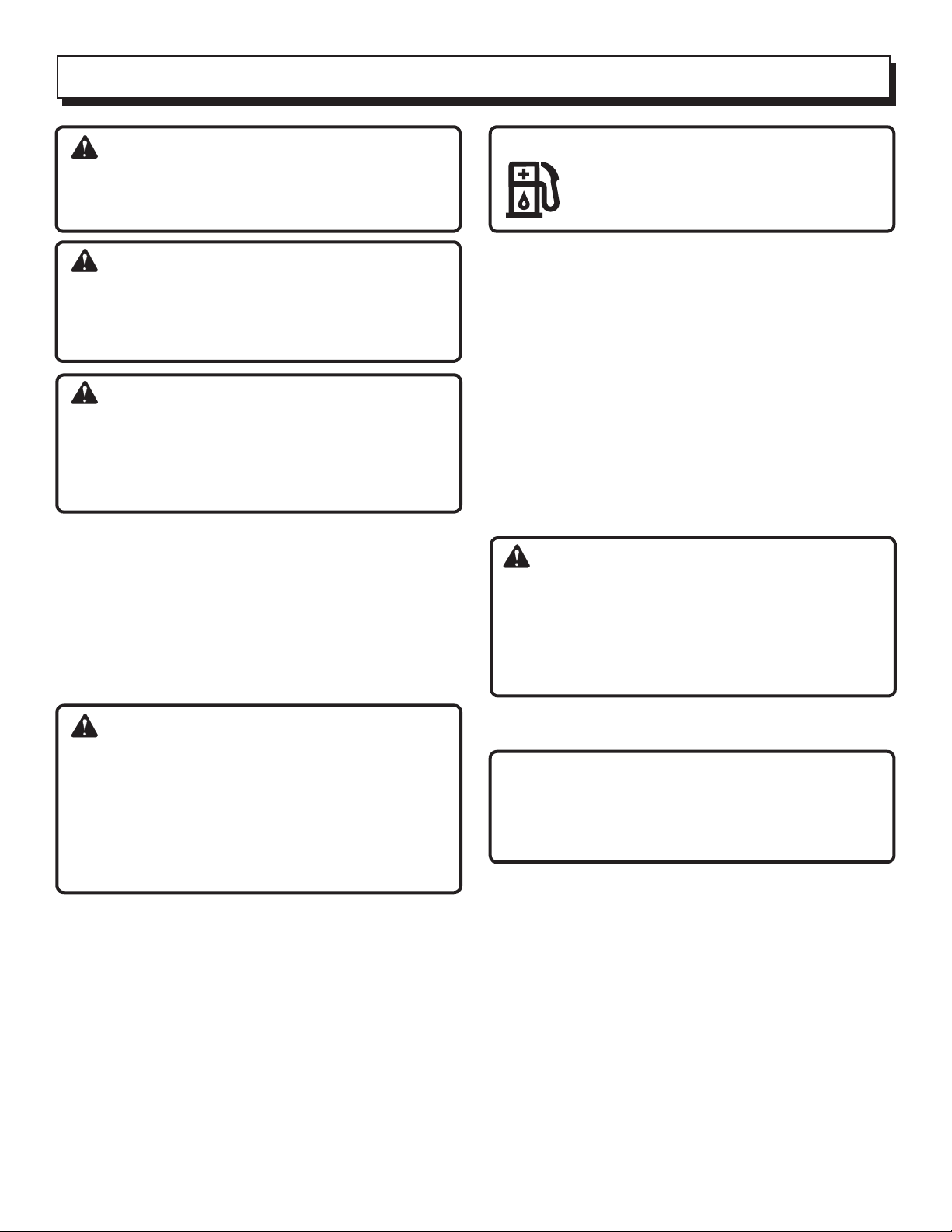
A - Air filter (filtro de aire)
B - Air filter cover (tapa del filtro de aire)
C - Knob (perilla)
A - Spark plug (bujía)
B - Spark plug boot (tapa de la bujía)
Fig. 16 Fig. 18
A - Cover (cubierta)
B - Screws (tornillos)
C - Muffler gasket (junta del silenciado)
D - Muffler (silenciador)
E - Spark arrestor (parachispas)
F - Plate (placa)
G - Muffler cover (cubierta del silenciador)
H - Screws (tornillos)
Fig. 17
A
B
A
B
C
A
B
H
G
B
E
D
C
F

2 — English
Introduction ...................................................................................................................................................................... 2
Introducción
General Safety Rules........................................................................................................................................................ 3
Reglas de seguridad generales
Specific Safety Rules........................................................................................................................................................ 4
Reglas de seguridad específicas
Symbols............................................................................................................................................................................ 5
Símbolos
Features............................................................................................................................................................................ 6
Características
Assembly.......................................................................................................................................................................... 6
Armado
Operation.....................................................................................................................................................................7-10
Funcionamiento
Maintenance..............................................................................................................................................................11-13
Mantenimiento
Troubleshooting.............................................................................................................................................................. 14
Solución de problemas
Warranty ....................................................................................................................................................................15-16
Garantía
Parts Ordering and Service ...............................................................................................................................Back Page
Pedidos de piezas y servicio Pág. posterior
This product has many features for making its use more pleasant and enjoyable. Safety, performance, and dependability
have been given top priority in the design of this product making it easy to maintain and operate.
* * *
Este producto ofrece numerosas características para hacer más agradable y placentero su uso. En el diseño de este
producto se ha conferido prioridad a la seguridad, el desempeño y la fiabilidad, por lo cual se facilita su manejo y
mantenimiento.
TABLE OF CONTENTS
INTRODUCTION

3 — English
WARNING:
Read and understand all instructions. Failure to follow
all instructions listed below may result in electric shock,
fire and/or carbon monoxide poisoning which will cause
death or serious personal injury.
Do not allow children or untrained individuals to use this
unit.
Do not start or operate the engine in a confined space,
building, near open windows, or in other unventilated
space where dangerous carbon monoxide fumes can
collect. Carbon monoxide, a colorless, odorless, and
extremely dangerous gas, can cause unconsciousness
or death.
Always wear eye protection with side shields marked to
comply with ANSI Z87.1, along with hearing protection.
Failure to do so could result in objects being thrown into
your eyes and other possible serious injuries.
Keep all bystanders, children, and pets at least 50 feet
away.
Wear heavy long pants, long sleeves, boots, and gloves.
Do not wear loose-fitting clothing, short pants, sandals,
jewelry of any kind, or go barefoot.
To reduce the risk of injury associated with objects being
drawn into rotating parts, do not wear loose clothing,
scarves, neck chains, and the like. Secure long hair so it
is above shoulder level to prevent entanglement in any
rotating parts.
Do not operate this unit when you are tired, ill, upset, or
under the influence of alcohol, drugs, or medication.
Do not operate in poor lighting.
Keep all parts of your body away from any moving parts
and all hot surfaces of the unit.
Wear a face filter mask in dusty conditions to reduce the
risk of injury associated with the inhalation of dust.
Check the work area before each use. Remove all objects
such as rocks, broken glass, nails, wire, or string which
can be thrown or become entangled in the machine.
Keep firm footing and balance. Do not overreach.
Overreaching can result in loss of balance or exposure
to hot surfaces.
Never operate the unit without a spark arrestor screen;
this screen is located inside the muffler.
Productuserson UnitedStates ForestServiceland, andin
somestates, mustcomply withfirepreventionregulations.
This product is equipped with a spark arrestor; however,
otheruser requirementsmayapply. Checkwith thefederal,
state, or local authorities in your area.
Before storing, allow the engine to cool.
Use only manufacturer’s replacement parts and
accessories.Failureto dosomay causepoorperformance
or possible injury.
Maintain the unit per maintenance instructions in this
Operator’s Manual.
Inspect the unit before each use for loose fasteners, fuel
leaks, etc. Replace damaged parts.
Do not use on a ladder, rooftop, tree, or other unstable
support. Stable footing on a solid surface enables better
control of the blower in unexpected situations.
SERVICE
Before cleaning, repairing, or inspecting, shut off the
engine and make certain all moving parts have stopped.
Disconnect the spark plug wire, and keep the wire away
from the plug to prevent starting.
Service on the blower must be performed by qualified
repair personnel only. Service or maintenance performed
by unqualified personnel could result in injury to the user
or damage to the product.
Use only identical replacement parts when servicing the
product. Use of unauthorized parts may create a risk of
serious injury to the user, or damage to the product.
GENERAL SAFETY RULES

4 — English
To reduce the risk of hearing loss associated with sound
level(s), hearing protection is required.
To reduce the risk of injury associated with contacting
rotating parts, stop the engine before installing or
removingattachments.Do notoperatewithout allguard(s)
andtubesinplace.Alwaysdisconnectthesparkplugbefore
performing maintenance or accessing any movable
parts.
Rotating impeller blades can cause severe injury. Do not
put hands or any other object into the blower housing air
outlet or blower tubes.
Do not point the blower nozzle in the direction of people
or pets.
Never run the unit without the blower tubes installed.
Never place objects inside the blower tubes.
Never use blower near fires, fireplaces, hot ashes, bar-
becue pits, etc., which may cause fire to spread.
Never place blower on any surface, except a hard, clean
surface when engine is running. Gravel, sand, and other
debris can be picked up by the air inlet and thrown at the
operator or bystanders, causing possible serious injuries.
Never use for spreading chemicals, fertilizers, toxic sub-
stances, or any other hazardous chemical.
Always hold the throttle control handle in your right hand.
Refer to the OPERATION section later in this manual for
additional information.
This product is intended for infrequent use by homeown-
ers and other occasional users for such general applica-
tions as blowing leaves and lawn clippings, etc. It is not
intended for prolonged use. Prolonged periods of opera-
tion can cause circulatory problems in the user’s hands
due to vibration. For such use, it may be appropriate to
use a product having an anti-vibration feature.
REFUELING
Fuel is highly flammable. Take precautions when using
to reduce the chance of serious personal injury.
Empty fuel tank and restrain the unit from moving before
transporting in a vehicle.
To reduce the risk of fire and burn injury, handle fuel with
care. It is highly flammable.
Do not smoke while handling fuel.
Mix and store fuel in a container approved for gasoline.
Mix fuel outdoors where there are no sparks or flames.
Select bare ground, stop engine, and allow to cool before
refueling.
Loosen fuel cap slowly to release pressure and to keep
fuel from escaping around the cap.
Tighten the fuel cap securely after refueling.
Wipe spilled fuel from the unit. Move 30 feet away from
refueling site before starting engine.
Never attempt to burn off spilled fuel under any circum-
stances.
Store fuel in a cool, well-ventilated area, safely away from
spark and/or flame-producing equipment.
Store fuel in containers specifically designed for this
purpose.
Only refuel outdoors and do not smoke while refueling.
Add fuel before starting the engine. Never remove the cap
of the fuel tank or add fuel while the engine is running or
when the engine is hot.
If fuel is spilled, do not attempt to start the engine but
move the machine away from the area of spillage and
avoid creating any source of ignition until fuel vapors
have dissipated.
Replace all fuel tank and container caps securely.
When draining the fuel tank, use an approved fuel storage
container while in a well-ventilated area.
Save these instructions. Refer to them frequently and use
them to instruct others who may use this product. If you
loan someone this product, loan them these instructions
also.
SPECIFIC SAFETY RULES

5 — English
The following signal words and meanings are intended to explain the levels of risk associated with this product.
SYMBOL SIGNAL MEANING
DANGER: Indicates an imminently hazardous situation, which, if not avoided, will result
in death or serious injury.
WARNING: Indicates a potentially hazardous situation, which, if not avoided, could result
in death or serious injury.
CAUTION: Indicates a potentially hazardous situation, which, if not avoided, may result in
minor or moderate injury.
NOTICE: (Without Safety Alert Symbol) Indicates important information not related to an
injury hazard, such as a situation that may result in property damage.
Some of the following symbols may be used on this product. Please study them and learn their meaning. Proper
interpretation of these symbols will allow you to operate the product better and safer.
SYMBOL NAME EXPLANATION
Safety Alert Symbol Indicates a potential personal injury hazard
Read Operator’s Manual To reduce the risk of injury, user must read and understand operator’s
manual before using this product
Eye and Hearing
Protection
Always wear eye protection with side shields marked to comply with
ANSI Z87.1 along with hearing protection.
Impeller Blades Contact with rotating impeller blades can cause severe injury.
Blower Tubes Do not operate without tubes in place.
Long Hair Risk of long hair being drawn into air inlet
Loose Clothing Risk of loose clothing being drawn into air intake
Keep Bystanders Away Keep all bystanders at least 50 ft. away.
Hot Surface To reduce the risk of injury or damage, avoid contact with any hot
surface.
Ricochet Thrown objects can ricochet and result in personal injury or property
damage.
Gasoline and Oil
Use unleaded gasoline intended for motor vehicle use with an oc-
tane rating of 87 [(R + M) / 2] or higher. This product is powered by a
2-cycle engine and requires pre-mixing gasoline and 2-cycle oil.
SYMBOLS

6 — English
KNOW YOUR BLOWER/VACUUM
See Figures 1 - 2.
The safe use of this product requires an understanding of
the information on the tool and in this operator’s manual
as well as a knowledge of the project you are attempting.
Before use of this product, familiarize yourself with all
operating features and safety rules.
BLOWER TUBE AND NOZZLE
The blower tubes can be assembled and installed on the
main housing using no tools.
ENGINE
The blower has a powerful 25.4cc engine with sufficient
power to handle tough blowing and vacuuming jobs.
MULCHER
The blower is equipped with a metal mulching blade that
efficiently reduces leaves at a 10:1 ratio.
SWEEPER NOZZLE
The sweeper nozzle allows for more area to be covered
during blower operation.
THROTTLE LOCK
The throttle lock feature allows the user to operate the
blower without holding the throttle trigger. To slow the
engine speed, simply push the throttle lock forward.
THROTTLE TRIGGER
The blower can be operated at any speed between idle
and full throttle.
VACUUM/MULCHER
Converting the blower to a vacuum/mulcher is simple and
can be done using a straight screwdriver.
VACUUM BAG
The vacuum bag attaches to the main housing easily by
using the vacuum bag adaptor.
VACUUM HANDLE
This feature allows user to perform vacuuming duties
comfortably.
VACUUM TUBES
The vacuum tubes can be installed on the main housing
using a flat head screw driver.
UNPACKING
This product requires assembly.
Carefully remove the product and any accessories from
the box. Make sure that all items listed in the packing list
are included.
WARNING:
Do not use this product if any parts on the Packing List
are already assembled to your product when you unpack
it. Parts on this list are not assembled to the product by
the manufacturer and require customer installation. Use
of a product that may have been improperly assembled
could result in serious personal injury.
Inspect the product carefully to make sure no breakage
or damage occurred during shipping.
Donot discardthe packingmaterialuntil youhave carefully
inspected and satisfactorily operated the product.
If any parts are damaged or missing, please call
1-800-726-5760 for assistance.
PACKING LIST
Blower
Grounding Wire
Upper Blower Tube
Sweeper Nozzle
Vacuum Handle
Vacuum Handle Knobs (2)
Upper and Lower Vacuum Tubes
Vacuum Tube Screws (2)
Vacuum Bag Assembly
Vacuum Bag Adaptor
2-Cycle Engine Lubricant
Operator’s Manual
PRODUCT SPECIFICATIONS
Engine Displacement.....................................................................................................................................................25.4cc
Air Velocity:
MPH......................................................................................................................................................................Up to 160
CFM ......................................................................................................................................................................Up to 420
FEATURES
ASSEMBLY

7 — English
WARNING:
If any parts are damaged or missing do not operate this
product until the parts are replaced. Use of this product
with damaged or missing parts could result in serious
personal injury.
WARNING:
Do not attempt to modify this product or create accesso-
ries not recommended for use with this product. Any such
alteration or modification is misuse and could result in a
hazardous condition leading to possible serious personal
injury.
WARNING:
To prevent accidental starting that could cause serious
personal injury, always disconnect the engine spark plug
wire from the spark plug when assembling parts.
TOOLS NEEDED
See Figure 3.
The following tool (not included or drawn to scale) is need-
ed for assembly:
Flathead Screwdriver
ASSEMBLING THE BLOWER TUBES
See Figure 4.
Align raised tabs on main housing to the slots on upper
tube; slide together and tighten securely by twisting.
Check tightness after initial run and retighten if needed.
Securethesweepernozzle andupperblowertube together
by aligning the raised locking tab on the upper blower
tube with the raised slot on the sweeper nozzle.
To disassemble, rotate the tube and nozzle to unlock
them and remove from the main housing outlet.
GROUNDING INSTRUCTIONS
A grounding wire is provided to help prevent static shock
when using the vacuum in low humidity conditions.
INSTALLING THE VACUUM HANDLE
See Figure 5.
Connect one end of the grounding wire to the grounding
tab located beneath the recoil housing.
Connect the other end of the grounding wire to one of
the vacuum handle knob posts.
Insert vacuum handle into the base of main housing.
Secure vacuum handle in place using vacuum handle
knobs.
INSTALLING THE VACUUM BAG
See Figures 6 - 7.
Remove the sweeper nozzle and upper blower tube from
the main housing by twisting and removing from main
housing outlet.
Unzip the vacuum bag and place the adaptor inside as
shown.Push thevacuumbag adaptor throughthe opening
opposite the zipper. The wider end of the adaptor will
remain on the inside of the vacuum bag when installed
properly.
Align the raised slots on the vacuum bag adaptor with the
raised locking tabs on the main housing outlet; push the
bag adaptor onto the housing. Twist to lock into place.
Rotate the vacuum bag until the shoulder strap is upright.
Make sure the vacuum bag is zipped and closed before
starting the unit.
INSTALLING THE VACUUM TUBES
See Figures 8 - 9.
WARNING:
Rotating impeller blades can cause severe injury. Always
stop the engine and ensure impeller blades have stopped
rotating before opening the vacuum door or installing/
changing tubes. Do not put hands or any other object
into the vacuum tubes while they are installed on the unit.
To install the vacuum tubes:
Secure the upper and lower vacuum tubes together by
aligning the raised locking tabs with the raised slots.
Tap tube assembly on ground until the screw holes in
lower tube are in the raised slot of the upper tube. Secure
with supplied screws. See figure 1.
Depress door tab using a straight screwdriver and open
vacuum inlet door.
Align screw mounts on vacuum opening with screws on
vacuum tube assembly.
Turning clockwise, tighten screws on upper vacuum tube
to secure to main housing.
To remove the vacuum tubes:
Loosen screws of the upper vacuum tube by turning
counterclockwise.
Removethevacuum tubeassemblyfromthemain housing.
Close the inlet cover door securely.
OPERATION
8 — English
WARNING:
Do not allow familiarity with tools to make you careless.
Remember that a careless fraction of a second is suf-
ficient to inflict serious injury.
WARNING:
Always wear eye protection with side shields marked to
comply with ANSI Z87.1, along with hearing protection.
Failure to do so could result in objects being thrown into
your eyes and other possible serious injuries.
WARNING:
Operation of this equipment may create sparks that can
start fires around dry vegetation. A spark arrestor may be
required. The operator should contact local fire agencies
for laws or regulations relating to fire prevention require-
ments.
APPLICATIONS
You may use this tool for the purposes listed below:
Clear leaves and other debris from your lawn
Keep decks and driveways free from leaves and pine
needles
Vacuuming leaves from your lawn
FUELING AND REFUELING
WARNING:
Gasoline is extremely flammable and explosive. A fire or
explosion from gasoline will burn you and others. Always
shut off engine before fueling. Never add fuel to a machine
with a running or hot engine. Move at least 30 ft. from
refueling site before starting engine. Do not smoke and
stay away from open flames and sparks. Failure to safely
handle fuel could result in serious personal injury.
Fuel Mixture
This product is powered by a 2-cycle engine and requires
pre-mixing gasoline and 2-cycle lubricant. Pre-mix unlead-
ed gasoline and 2-cycle engine lubricant in a clean con-
tainer approved for gasoline. DO NOT mix quantities larger
than usable in a 30-day period.
Recommended fuel: This engine is certified to operate on
unleaded gasoline intended for automotive use.
Note: We recommend you use high-quality synthetic 2-cycle
lubricant in this product. Mix at 2.6 oz. per gallon (US).
Do not use automotive lubricant or 2-cycle outboard
lubricant.
HIGH QUALITY 2-CYCLE ENGINE LUBRICANT
GASOLINE LUBRICANT
1.0 gal. (US) (3.8 liter) 2.6 oz. (76 ml)
2.5 gal. (US) (9.5 liter) 6.4 oz. (189 ml)
FILLING THE TANK
Clean the surface around the fuel cap to prevent
contamination.
Loosenthe fuelcap slowly,by turning itcounterclockwise.
Pour the fuel mixture carefully into the tank.
Clean and inspect the fuel cap gasket before replacing
the fuel cap.
Replace the fuel cap and tighten it by turning it clockwise.
Wipe spilled fuel from the product.
Move at least 30 ft. (9 m) away from refueling area before
starting the product.
Note: It is normal for smoke to be emitted from a new en-
gine during first use.
WARNING:
Always shut off engine before fueling. Never add fuel to
a machine with a running or hot engine. Move at least
30 ft (9 m). from refueling site before starting engine. Do
not smoke and stay away from open flames and sparks.
Failure to safely handle fuel could result in serious per-
sonal injury.
OXYGENATED FUELS
NOTICE:
Do not use E15, E20, or E85 fuel (or fuel containing
greater than 10% ethanol) in this product. It is a viola-
tion of federal law and will damage the unit and void
your warranty.
Fuel system damage or performance problems resulting
from the use of an oxygenated fuel containing more
than the percentage of oxygenates stated below are not
covered under warranty.
Ethanol. Gasoline containing up to 10% ethanol by volume
(commonly referred to as E10) is acceptable. E15, E20, and
E85 are not.
OPERATION
9 — English
STARTING AND STOPPING
See Figures 10 - 11.
To start a cold engine:
Set the blower vac on a flat, bare surface.
Slowly press the primer bulb 8 times.
Note: After the 8th press, fuel should be visible in the
primer bulb. If it is not, continue to press the primer until
you see fuel in the bulb.
Place the choke lever in the FULL CHOKE position.
Pull throttle lock back to lock the throttle wide open.
Pull the starter grip and rope sharply until engine attempts
to run. Do not pull the starter grip more than four (4) times.
Set the choke lever in the HALF CHOKE position.
Pull the starter grip and rope until the engine runs. Do
not pull the starter grip more than six (6) times.
Note: If the engine does not start, return to the FULL
CHOKE position and repeat steps 3 through 6 again.
Allow the engine to run for 20 seconds, then place the
choke lever in the RUN position.
Note:In coolerenvironments,additionalpulls ofthestarter
handle may be required with the choke lever in the FULL
CHOKE position.
To start warm engine:
Place the choke lever in the RUN position.
Pull throttle lock back to lock the throttle wide open.
Pull the starter grip and rope until the engine runs.
Note: If the engine does not start, repeat steps 3 through
7 again.
To stop the engine:
Press and hold the stop switch in the stop “ ” position
until the engine stops. The switch will automatically return
to the on (I) position when released.
OPERATING THE BLOWER
See Figures 12 - 13.
WARNING:
Never run the unit without the blower tubes installed or
the vacuum door securely closed. Failure to follow these
steps could result in possible serious injuries.
WARNING:
Always wear eye protection with side shields marked to
comply with ANSI Z87.1, along with hearing protection.
Failure to do so could result in objects being thrown into
your eyes and other possible serious injuries.
Start the blower. Refer to Starting and Stopping earlier
in this manual. Hold the blower with the upper handle in
your right hand.
WARNING:
Always hold the blower away from your body with the
handle in your right hand when operating as a blower,
keeping clearance between your body and the product.
The muffler side of the blower should be away from your
body. Any contact with the housing can result in burns
and/or other serious personal injury.
WARNING:
Do not place blower on top of or near loose debris or
gravel. Debris may be sucked into blower intake vent
resulting in possible damage to the unit and could result
in serious personal injury.
To keep from scattering debris, blow around the outer
edges of a debris pile. Never blow directly into the center
of a pile.
Operate power equipment at reasonable hours only - not
early in the morning or late at night when people might be
disturbed.Complywith thetimeslisted inlocalordinances.
To reduce sound levels, limit the number of pieces of
equipment used at any one time.
Conserve water by using power blowers instead of hoses
for many lawn and garden applications, including areas
such as gutters, screens, patios, grills, porches, and
gardens.
Operate blower at the lowest possible throttle speed to
do the job.
Check your equipment before operation, especially the
muffler, air intakes, and air filters.
Use rakes and brooms to loosen debris before blowing.
In dusty conditions, slightly dampen surfaces when water
is available.
Watch out for children, pets, open windows, or freshly
washed cars, and blow debris safely away.
Use the sweeper nozzle so the air stream can work close
to the ground.
After using blowers or other equipment, CLEAN UP!
Dispose of debris properly.
Use the sweeper nozzle for the everyday blowing
operation. This nozzle allows for more area to be covered
during the blowing operation.
OPERATION

10 — English
THROTTLE LOCK
See Figure 14.
The throttle lock can be used to operate the blower without
holding the throttle trigger.
To engage the throttle lock:
Pull throttle lock back towards user, and stop at the
desired throttle setting.
To release the throttle lock, push throttle lock all the way
towards the front of unit.
VACUUM OPERATION
See Figure 15.
WARNING:
Never run the unit without the vacuum tubes and vacuum
bag installed. Failure to do so could result in serious
personal injury.
WARNING:
Always wear eye protection with side shields marked to
comply with ANSI Z87.1, along with hearing protection.
Failure to do so could result in objects being thrown into
your eyes and other possible serious injuries.
WARNING:
Keep the muffler and all hot surfaces of the blower/
vacuum away from your body. Failure to do so could
result in possible serious personal injury.
Install the vacuum tubes, vacuum handle, and bag. Refer
to the Assembly section earlier in this manual.
Start the engine. Refer to Starting and Stopping earlier
in this manual.
Place the vacuum bag strap over your right shoulder.
Hold the upper handle in your left hand and the vacuum
handle in your right hand.
Move the vacuum from side to side along outer edge of
the debris. To avoid clogging, do not place the vacuum
tube directly into the debris pile.
Hold the engine higher than the inlet end of the vacuum
tube.
Always point vacuum tube downhill when working on a
hillside.
To avoid injury to the operator or unit, do not pick up
rocks, broken glass, bottles, or other similar objects.
If the vacuum tubes should clog, stop the engine and
disconnect the spark plug wire before cleaning out the
obstruction.
Remove the vacuum tubes and clear the debris from
the blower fan housing. Remove the bag and clear the
adaptor. A small rod or stick may be required to clear the
entire tube length. Ensure that all debris has been cleared
before reassembling the vacuum tubes.
OPERATION
11 — English
WARNING:
Use only identical replacement parts when servicing this
product. Use of any other parts could create a hazard or
cause product damage.
WARNING:
Always wear eye protection with side shields marked to
comply with ANSI Z87.1, along with hearing protection.
Head protection may also be required depending on the
type of attachment used and as prescribed in the attach-
ment’s Operator’s Manual. Failure to do so could result in
objects being thrown into your eyes and other possible
serious injuries.
WARNING:
Before inspecting, cleaning, or servicing the machine,
shut off engine, wait for all moving parts to stop, and
disconnect spark plug wire and move it away from spark
plug. Failure to follow these instructions can result in
serious personal injury or property damage.
GENERAL MAINTENANCE
Avoid using solvents when cleaning plastic parts. Most
plastics are susceptible to damage from various types of
commercial solvents and may be damaged by their use.
Use clean cloths to remove dirt, dust, lubricant, grease, etc.
WARNING:
Do not at any time let brake fluids, gasoline, petroleum-
based products, penetrating lubricants, etc., come in con-
tact with plastic parts. Chemicals can damage, weaken or
destroy plastic which can result in serious personal injury.
CLEANING THE PRODUCT
Stop the product before cleaning.
Clean the exterior of the product with a damp cloth.
Avoid using solvents when cleaning plastic parts. Most
plastics are susceptible to damage from various types of
commercial solvents and may be damaged by their use.
Scrape debris away from air intake vents on both sides
of the motor housing.
NOTICE:
Keeping air intake vents free of grass and debris prevents
motor overheating and possible failure.
SERVICING THE PRODUCT
Check and tighten all fasteners. If any part is damaged or
lost, repair it or replace it.
CHECKING THE FUEL CAP, TANK, AND LINES
WARNING:
Check for fuel leaks. A leaking fuel cap, tank, or lines
are a fire hazard and must be replaced immediately. If
you find any leaks, correct the problem before using the
product. Failure to do so could result in a fire that could
cause serious personal injury.
The fuel cap contains a non-serviceable filter and check
valve. A clogged fuel filter causes poor engine perfor-
mance. If performance improves when the fuel cap is loos-
ened, the check valve may be faulty or the filter may be
clogged. Replace the fuel cap if necessary.
CLEANING AIR FILTER
See Figure 16.
A wet or dirty air filter can affect the way the engine starts,
performs, and wears. The air filter should be checked and
cleaned after 5 hours of operation. Inspect and clean more
frequently if used in dusty dirty conditions.
For best performance, the air filter should be replaced ev-
ery 25 hours or yearly.
To clean the air filter:
Loosen the knob on the air filter cover.
Remove the cover.
Lift the edge of the air filter carefully and peel it out.
Wash the air filter with warm, soapy water.
Rinse and squeeze to dry.
Reinstall the air filter.
Note: Make sure the filter is seated properly inside the
cover. Installing the filter incorrectly will allow dirt to enter
the engine, causing rapid engine wear.
Install the air filter cover.
Tighten knob to secure.
MAINTENANCE

12 — English
CLEANING THE EXHAUST PORT, MUFFLER,
AND SPARK ARRESTOR
See Figure 17.
WARNING:
Stop engine, remove spark plug boot, and allow engine
and muffler to cool before replacing the spark arrestor.
Contact with a hot muffler or engine could cause burns
or other serious personal injuries.
NOTE: Depending on the type of fuel used, the type and
amount of lubricant used, and/or your operating condi-
tions, the exhaust port, muffler, and/or spark arrestor
screen may become blocked with carbon deposits. If you
notice a power loss with your gas powered tool, you may
need to remove these deposits to restore performance. We
highly recommend that only qualified service technicians
perform this service.
The spark arrestor may need to be cleaned or replaced
after repeated use. If replacement is necessary, use part
number 638268001.
TO REPLACE THE SPARK ARRESTOR:
Remove the five screws that hold the cover.
Note: Removing these screws requires the use of a T20
and T25 torx screwdriver.
Remove the cover.
Remove the two screws holding the muffler assembly in
place.
Remove the muffler assembly and muffler gasket. It may
be necessary to work the muffler assembly free from the
muffler gasket.
Separate the muffler cover from the muffler.
Remove the three screws that hold the plates on the
muffler.
Remove the spark arrestor.
Replace the old spark arrestor with the new one.
Assemble the muffler by reinstalling the plates
and tightening the three screws (torque to 18 in.lb
[2.03 Nm] minimum, 22 in.lb. [2.48 Nm] maximum).
Reassemble the muffler and muffler cover and attach to
the muffler gasket with the two screws.
Reinsert the muffler assembly and tighten two screws to
engine (torque to 60 in.lb [6.78 Nm] minimum, 80 in.lb.
[9.04 Nm] maximum).
Reinstall the cover on the tool and fasten with the
five screws (torque to 26 in.lb [2.94 Nm] minimum,
39 in.lb. [4.41 Nm] maximum).
Note: Do not over-tighten screws.
WARNING:
To avoid a fire hazard, never run the without the spark
arrestor in place.
VACUUM BAG
A dirty bag will reduce performance. To clean the bag, turn
it inside out and shake. Wash the bag in soapy water at
least once a year. Replacement parts available online at
www.blackmaxtools.com.
SPARK PLUG REPLACEMENT
See Figure 18.
This engine uses a RCJ6Y or RCJ4 spark plug. Use an ex-
act replacement every 25 hours or annually.
Remove the spark plug boot.
Loosen the spark plug by turning it counterclockwise with
a socket.
Remove the spark plug.
Inspect the new spark plug. The spark plug must be
properly gapped and free of deposits in order to ensure
properengineoperation.The correctgap isapproximately
0.025 in. (0.64 mm). To widen gap, if necessary, carefully
bend the ground (top) electrode. To lessen gap, gently
tap ground electrode on a hard surface.
Hand thread the new spark plug into the cylinder , turning
it clockwise.
Tighten with a socket. (torque to 170 in.lb. [19.21 Nm]
minimum, 190 in.lb. [21.47 Nm] maximum.) Do not over-
tighten.
NOTICE:
Be careful not to cross-thread the spark plug. Cross-
threading will seriously damage the product.
STORING THE PRODUCT
Clean all foreign material from the product. Store unit
indoors in a dry, well-ventilated area that is inaccessible
to children. Keep away from corrosive agents such as
garden chemicals, fertilizer, and de-icing salts.
Abide by all ISO and local regulations for the safe storage
and handling of gasoline.
When storing 1 month or longer:
Drain all fuel from tank into a container approved for
gasoline.
Run engine until it stops.
Place choke lever in the FULL CHOKE position.
Pull throttle lock back to lock the throttle.
Attempt to start the engine five (5) more times.
MAINTENANCE

13 — English
This Product Was Manufactured With A Catalyst Muffler
Congratulations! You have made an investment toward protecting the environment. In order to maintain this product’s
original emission level, please refer to the maintenance section below.
EMISSIONS MAINTENANCE SCHEDULE AND WARRANTED PARTS LIST
Emissions Parts Inspect Before Clean Every Replace Clean Every Replace Every
Each Use 5 Hours Every 25 Hours 25 Hours 125 Hours
or Yearly or Yearly
*CATALYTIC MUFFLER ASSEMBLY.................................................................................................................. X
AIR FILTER ASSY
includes:
Filter ................................................................. X............................. X
SPARK SCREEN ..................................................................................................................X
CARBURETOR ASSY
includes:
Heat Dam
Gaskets
FUEL TANK ASSY
includes:
Fuel Lines........................ X
Fuel Cap.......................... X
Fuel Filter
IGNITION ASSY
includes:
Spark Plug........................................................................................ X
*NOTICE: THE USE OF EMISSION CONTROL COMPONENTS OTHER THAN THOSE DESIGNED FOR THIS UNIT IS
A VIOLATION OF FEDERAL LAW.
CALL
1-800-726-5760
www.blackmaxtools.com
CALL US FIRST
For any questions about operating or maintaining your product,
call the Black Max Help Line!
Your product has been fully tested prior to shipment to ensure
your complete satisfaction.
MAINTENANCE

14 — English
PROBLEM CAUSE REMEDY
Engine fails to start. 1. No fuel in tank.
2. Spark plug shorted or fouled.
3. Spark plug is broken (cracked porcelain
or electrodes broken).
4. Ignition lead wire shorted, broken, or
disconnected from spark plug.
5. Ignition inoperative.
1. Fill tank with fresh fuel/oil mixture.
2. Replace spark plug.
3. Replace spark plug.
4. Replace lead wire or attach to spark plug.
5. Contact authorized service center.
Engine hard to start. 1. Water in gasoline or stale fuel mixture.
2. Too much oil in fuel mixture.
3. Engine is under or over-choked.
4. Weak spark at spark plug.
1. Drain entire system and refill with fresh fuel/
oil mixture.
2. Drain and refill with correct fresh fuel/oil
mixture.
3. Adjust choke as necessary.
4. Contact authorized service center.
Engine lacks power. 1. Air filter clogged.
2. Spark plug fouled.
3. Spark arrestor/muffler/exhaust port
deposits.
1. Clean/replace the air filter.
2. Replace the spark plug.
3. Clean/replace spark arrestor /muf fler parts
as required.
Engine overheats. 1. Insufficient oil in fuel mixture. 1. Mix fuel and oil as described in starting
instructions.
IF THESE SOLUTIONS DO NOT SOLVE THE PROBLEM, CONTACT YOUR AUTHORIZED SERVICING DEALER.
TROUBLESHOOTING

15 — English
LIMITED WARRANTY STATEMENT
OWTIndustries, Inc.,warrantsto theoriginalretailpurchaser
that this Black Max brand outdoor product is free from
defect in material and workmanship and agrees to repair or
replace, at OWT Industries, Inc.’s, discretion, any defective
product free of charge within these time periods from the
date of purchase.
Two years if the product is used for personal, family or
household use;
90days,ifusedfor any otherpurpose, such ascommercial
or rental.
This warranty extends to the original retail purchaser only
and commences on the date of the original retail purchase.
Any part of this product found in the reasonable judgment
of OWT Industries, Inc. to be defective in material or
workmanship will be repaired or replaced without charge
for parts and labor by an authorized service center for
Black Max brand outdoor products (Authorized Black Max
Service Center).
The product, including any defective part, must be returned
to an authorized Black Max service center within the
warranty period. The expense of delivering the product to
the service center for warranty work and the expense of
returning it back to the owner after repair or replacement will
be paid by the owner. OWT Industries, Inc.’s, responsibility
in respect to claims is limited to making the required repairs
or replacements and no claim of breach of warranty shall
be cause for cancellation or rescission of the contract of
sale of any Black Max brand outdoor product. Proof of
purchase will be required by the dealer to substantiate any
warranty claim. All warranty work must be performed by an
authorized service dealer.
This warranty is limited to ninety (90) days from the date of
original retail purchase for any Black Max brand outdoor
product that is used for rental or commercial purposes, or
any other income-producing purpose.
This warranty does not cover any product that has been
subject to misuse, neglect, negligence, or accident, or that
has been operated in any way contrary to the operating
instructions as specified in this operator’s manual. This
warranty does not apply to any damage to the product that
is the result of improper maintenance or to any product that
has been altered or modified. The warranty does not extend
to repairs made necessary by normal wear or by the use
of parts or accessories which are either incompatible with
the Black Max brand outdoor product or adversely affect
its operation, performance, or durability. In addition, this
warranty does not cover:
A. Tune-ups – Spark Plugs, Carburetor, Carburetor
Adjustments, Ignition, Filters
B. Wear items – Bump Knobs, Outer Spools, Cutting Lines,
Inner Reels, Starter Pulleys, Starter Ropes, Drive Belts,
Tines,Felt Washers,Hitch Pins,MulchingBlades, Blower
Fans, Blower and Vacuum Tubes, Vacuum Bag and
Straps, Guide Bars, Saw Chains
OWTIndustries, Inc., reserves the righttochange orimprove
the design of any Black Max brand outdoor product without
assuming any obligation to modify any product previously
manufactured.
ALL IMPLIED WARRANTIES ARE LIMITED IN DURATION
TO THE STATED WARRANTY PERIOD. ACCORDINGLY,
ANY SUCH IMPLIED WARRANTIES INCLUDING
MERCHANTABILITY, FITNESS FOR A PARTICULAR
PURPOSE, OR OTHERWISE, ARE DISCLAIMED IN THEIR
ENTIRETYAFTERTHEEXPIRATIONOFTHEAPPROPRIATE
TWO-YEAR, ONE-YEAR, OR NINETY-DAY WARRANTY
PERIOD.OWT INDUSTRIES,INC.’S, OBLIGATION UNDER
THIS WARRANTY IS STRICTLY AND EXCLUSIVELY
LIMITED TO THE REPAIR OR REPLACEMENT OF
DEFECTIVE PARTS AND OWT INDUSTRIES, INC., DOES
NOT ASSUME OR AUTHORIZE ANYONE TO ASSUME
FOR THEM ANY OTHER OBLIGATION. SOME STATES DO
NOT ALLOW LIMITATIONS ON HOW LONG AN IMPLIED
WARRANTYLASTS,SOTHE ABOVE LIMITATION MAY NOT
APPLY TO YOU. OWT INDUSTRIES, INC., ASSUMES NO
RESPONSIBILITY FOR INCIDENTAL, CONSEQUENTIAL,
OR OTHER DAMAGES INCLUDING, BUT NOT LIMITED
TO, EXPENSE OF RETURNING THE PRODUCT TO AN
AUTHORIZED BLACK MAX SERVICE CENTER AND
EXPENSE OF DELIVERING IT BACK TO THE OWNER,
MECHANIC’STRAVELTIME,TELEPHONE ORTELEGRAM
CHARGES, RENTAL OF A LIKE PRODUCT DURING THE
TIME WARRANTY SERVICE IS BEING PERFORMED,
TRAVEL, LOSS OR DAMAGE TO PERSONAL PROPERTY,
LOSS OF REVENUE, LOSS OF USE OF THE PRODUCT,
LOSS OF TIME, OR INCONVENIENCE. SOME STATES
DO NOT ALLOW THE EXCLUSION OR LIMITATION OF
INCIDENTAL OR CONSEQUENTIAL DAMAGES, SO THE
ABOVE LIMITATION OR EXCLUSION MAY NOT APPLY
TO YOU.
This warranty gives you specific legal rights, and you may
also have other rights which vary from state to state.
This warranty applies to all Black Max brand outdoor
products manufactured by or for OWT Industries, Inc.,
and sold in the United States and Canada.
To locate your nearest Authorized Black Max Service
Center, dial 1-800-726-5760.
WARRANTY

16 — English
THE FOLLOWING CALIFORNIA AIR RESOURCES BOARD (CARB) STATEMENT ONLY APPLIES TO MODEL NUMBERS
REQUIRED TO MEET THE CARB REQUIREMENTS.
The U.S. Environmental Protection Agency (EPA), the California Air Resources
Board (CARB), and OWT Industries, Inc., are pleased to explain the Emissions
Control System Warranty on your 2014 model year non-road or small off-road
engine. In California, new equipment that uses small off-road engines must be
designed, built, and equipped to meet the state’s stringent anti-smog standards. In
other states, new 2000 and later model year non-road engines must be designed,
built, and equipped at the time of sale to meet the U.S. EPA regulations for small
non-road engines. The non-road engine must be free from defects in materials
and workmanship which cause it to fail to conform with U.S. EPA standards for the
first two years of engine use from the date of sale to the ultimate purchaser. OWT
Industries, Inc., must warrant the emission control system on your non-road or
small off-road engine for the period of time listed above provided there has been no
abuse, neglect, or improper maintenance of your non-road or small off-road engine.
Your emission control system may include parts such as the carburetor or fuel
injection system, the ignition system, catalytic converters, fuel tanks, valves, filters,
clamps, connectors, and other associated components. Also included may be
hoses, belts and connectors, and other emission-related assemblies.
Where a warrantable condition exists, OWT Industries, Inc., will repair your non-road
or small off-road engine at no cost to you, including diagnosis, parts, and labor
performed at an authorized service center for Black Max brand outdoor products.
MANUFACTURER’S WARRANTY COVERAGE:
This product’s emissions control system is warranted for two years. If any emission-
related part on your engine is defective, the part will be repaired or replaced by
OWT Industries, Inc., free of charge.
OWNER’S WARRANTY RESPONSIBILITIES
(a) As the non-road or small off-road engine owner, you are responsible for the
performance of the required maintenance listed in your operator’s manual. OWT
Industries, Inc., recommends that you retain all receipts covering maintenance
on your non-road or small off-road engine, but OWT Industries, Inc., cannot deny
warranty solely for the lack of receipts or for your failure to ensure the performance
of all scheduled maintenance. Any replacement part or service that is equivalent
in performance and durability may be used in non-warranty maintenance or
repairs, and shall not reduce the warranty obligations of OWT Industries, Inc.
(b) As the non-road or small off-road engine owner, you should be aware, however,
that OWT Industries, Inc., may deny you warranty coverage if your non-road or small
off-road engine or a part has failed due to abuse, neglect, improper maintenance,
or unapproved modifications.
(c) You are responsible for presenting your non-road or small off-road engine to an
authorized service dealer as soon as a problem exists. The warranty repairs should
be completed in a reasonable amount of time, not to exceed 30 days.
If you have any questions regarding your warranty rights and responsibili-
ties, you should contact a OWT Industries, Inc., Customer Representative at
1-800-726-5760.
DEFECT WARRANTY COVERAGE REQUIREMENTS:
(a) The warranty period begins on the date the engine or equipment is delivered
to an ultimate purchaser.
(b) General Emissions Warranty Coverage. OWT Industries, Inc., warrants to the
ultimate purchaser and each subsequent purchaser that your non-road or small
off-road engine is designed, built, and equipped at the time of sale to conform
with all applicable regulations adopted by the California Air Resources Board or
the United States Environmental Protection Agency; and that it is free from defects
in materials and workmanship which cause the engine to fail to conform with ap-
plicable regulations for a period of two years from the date the non-road or small
off-road engine is purchased by the initial purchaser.
(c) The warranty on emissions-related parts will be interpreted as follows: Any
warranted part that is not scheduled for replacement as required in the Emissions
Maintenance Schedule and Warranty Parts List set forth below is warranted for
two years. If any such part (including any part that is scheduled only for regular
inspection) fails during the period of warranty coverage, it will be repaired or re-
placed at any Black Max Authorized Service Center at no charge. Any such part
repaired or replaced under warranty will be warranted for the remaining warranty
period. A statement to the effect of “repair or replace as necessary” would not
reduce the period of warranty coverage. Any warranted part that is scheduled for
replacement as required maintenance in the Emissions Maintenance Schedule and
Warranty Parts List is warranted for the period of time prior to the first scheduled
replacement point for that part. Any such part repaired or replaced under warranty
is warranted for the remainder of the period prior to the first scheduled replace-
ment point, and will be repaired or replaced at any Black Max Authorized Service
Center for no charge until that replacement point is reached.
OWT Industries, Inc., shall remedy warranty defects at any authorized Black Max
Authorized Service Center, including any distribution center that may be franchised
to service the subject engines. Any diagnostic work done at a Black Max Authorized
Service Center shall be free of charge to the owner if such work determines that a
warranted part is defective. Any manufacturer-approved or equivalent replacement
part may be used for any warranty maintenance or repairs on emission-related
parts, and must be provided free of charge to the owner if the part is still under
warranty. OWT Industries, Inc., is liable for damages to other engine components
caused by the failure of a warranted part still under warranty.
Add-on or modified parts that are not exempted by the California Air Resource
Board may not be used. The use of any non-exempted add-on or modified parts
will be grounds for disallowing a warranty claim. OWT Industries, Inc., will not be
liable to warrant failures of warranted parts caused by the use of a non-exempted
add-on or modified part.
The California Air Resources Board’s Emission Warranty Parts List specifically
defines the emission-related warranted parts. (EPA’s regulations do not include
a parts list, but the EPA considers emission-related warranted parts to include
all the parts listed below.) OWT Industries, Inc., will provide any documents that
describe its warranty procedures or policies within five days upon request by the
California Air Resources Board.
EMISSIONS PARTS LIST
Emissions parts vary from product to product. Your emissions control system
warranty applies to any of the following components that may be included on
your product:
(1) Fuel Metering System
(i) Carburetor and internal parts (and/or pressure regulator or fuel injection
system).
(ii) Air/fuel ratio feedback and control system.
(iii) Cold start enrichment system.
(iv) Fuel Tank.
(2) Air Induction System
(i) Controlled hot air intake system.
(ii) Intake manifold.
(iii) Air filter.
(3) Ignition System
(i) Spark Plugs.
(ii) Magneto or electronic ignition system.
(iii) Spark advance/retard system.
(4) Exhaust Gas Recirculation (EGR) System
(i) EGR valve body and carburetor spacer, if applicable.
(ii) EGR rate feedback and control system.
(5) Air Injection System
(i) Air pump or pulse valve.
(ii) Valves affecting distribution of flow.
(iii) Distribution manifold.
(6) Catalyst or Thermal Reactor System
(i) Catalytic converter.
(ii) Thermal reactor.
(iii) Exhaust manifold.
(7) Particulate Controls
(i) Traps, filters, precipitators, and any other device used to capture particulate
emissions.
(8) Miscellaneous Items Used in Above Systems
(i) Electronic controls.
(ii) Vacuum, temperature, and time sensitive valves and switches.
(iii) Hoses, belts, connectors, and assemblies.
OWT Industries, Inc., will furnish with each new engine written instructions for its
maintenance and use by the owner.
The Emissions Compliance Period referred to on the Emissions Compliance label
indicates the number of operating hours for which the engine has been shown to
meet Federal emission requirements. Category C=50 hours, B=125 hours, and
A=300 hours.
OWT INDUSTRIES, INC., LIMITED WARRANTY STATEMENT FOR FEDERAL AND CALIFORNIA EMISSION CONTROL
SYSTEMS NON-ROAD AND SMALL OFF-ROAD ENGINES
YOUR WARRANTY RIGHTS AND OBLIGATIONS
WARRANTY
Table of contents
Languages:
Other Black Max Blower manuals


