Black BLK-IPE4101 User manual

4-Channel H.264
Network Video Encoder
User Manual
Product: BLK-IPE4101
Please read this manual before using your encoder, and always follow the instructions for
safety and proper use. Save this manual for future reference.
BLK-IPE4101_PM
8/1/11

ii www.digiop.com
WARNING
RISK OF ELECTRIC SHOCK. DO NOT OPEN.
To reduce the risk of electric shock, do not
remove cover (or back). No user serviceable
parts inside. Refer servicing to qualied
service personnel.
CAUTION
Operate this encoder only in environments where the temperature or humidity is within the recommended range.
Operation in extreme temperatures or humidity levels may cause electric shock and shorten the life of the product.
LEGAL NOTICE
DIGIOP™ products are designed to meet safety and performance standards with the use of specic DIGIOP™
authorized accessories. DIGIOP™ disclaiSupercirms liability associated with the use of non-DIGIOP™ authorized
accessories.
The recording, transmission, or broadcast of any person’s voice without their consent or a court order is strictly
prohibited by law.
DIGIOP™ makes no representations concerning the legality of certain product applications such as the making,
transmission, or recording of video and/or audio signals of others without their knowledge and/or consent. We
encourage you to check and comply with all applicable local, state, and federal laws and regulations before
engaging in any form of surveillance or any transmission of radio frequencies.
Other trademarks and trade names may be used in this document to refer to either the entities claiming the marks
and names or their products. DIGIOP, Inc. disclaims any proprietary interest in trademarks and trade names other
than its own.
Microsoft, Windows , and Internet Explorer are either registered trademarks or trademarks of Microsoft Corporation in
the United States and/or other countries.
No part of this document may be reproduced or distributed in any form or by any means without the express written
permission of DIGIOP, Inc.
© 2011 by DIGIOP, Inc. All Rights Reserved.
3850 Priority Way South Drive, Suite 200, Indianapolis, IN 46240
Sales/Support: 1.877.972.2522

14-Channel H.264 Network Video Encoder
Table of Contents
SECTION1 Features...........................................................................2
1.1 Frontpanelindicatorsandconnectors...................................................3
1.2 Backpanelconnectors................................................................4
SECTION2 InstallationandSetup...............................................................5
2.1 What’sinthebox ....................................................................5
2.2 Toolsyouneed.......................................................................5
2.3 Installtheencoder...................................................................5
2.4 Connections.........................................................................6
2.4.1 Audio in/out connections (Ain, Aout, channels 1 - 4) . . . . . . . . . . . . . . . . . . . . . . . . . . . . . . . . . .7
2.4.2 Sensorinconnection(DI,channels1-4)............................................7
2.4.3 Digitalout(DO)connection.......................................................8
2.4.4 RS-485 device connection. . . . . . . . . . . . . . . . . . . . . . . . . . . . . . . . . . . . . . . . . . . . . . . . . . . . . . . . .9
2.4.5 RS-232Cdeviceconnection ......................................................10
2.4.6 LAN,video,andpowerconnections ...............................................10
2.5 InstallIPAdminTool.................................................................11
2.6 Conguretheencodernetworksettings................................................12
2.6.1 Conguring encoders on networks with DHCP . . . . . . . . . . . . . . . . . . . . . . . . . . . . . . . . . . . . . .12
2.6.2 Conguring encoders on networks without DHCP . . . . . . . . . . . . . . . . . . . . . . . . . . . . . . . . . . .15
2.7 SetuptheencoderBasicConguration.................................................20
2.7.1 Image quality adjustments. . . . . . . . . . . . . . . . . . . . . . . . . . . . . . . . . . . . . . . . . . . . . . . . . . . . . . .24
2.7.2 Setup sensor (DI) and alarm (DO) reporting. . . . . . . . . . . . . . . . . . . . . . . . . . . . . . . . . . . . . . . . .25
2.8 Finalinstallationchecks..............................................................27
2.9 Cleaning...........................................................................29
SECTION3 Specications .....................................................................30
APPENDIXA Troubleshooting...................................................................32
A.1 Rebootencoder.....................................................................32
A.2 Set encoder to factory default network settings . . . . . . . . . . . . . . . . . . . . . . . . . . . . . . . . . . . . . . . . .32
A.3 Checkrmwareversion..............................................................33
A.4 Support ...........................................................................33
APPENDIXB Dimensions .......................................................................34
2www.digiop.com
SECTION 1: FEATURES
SECTION 1
Features
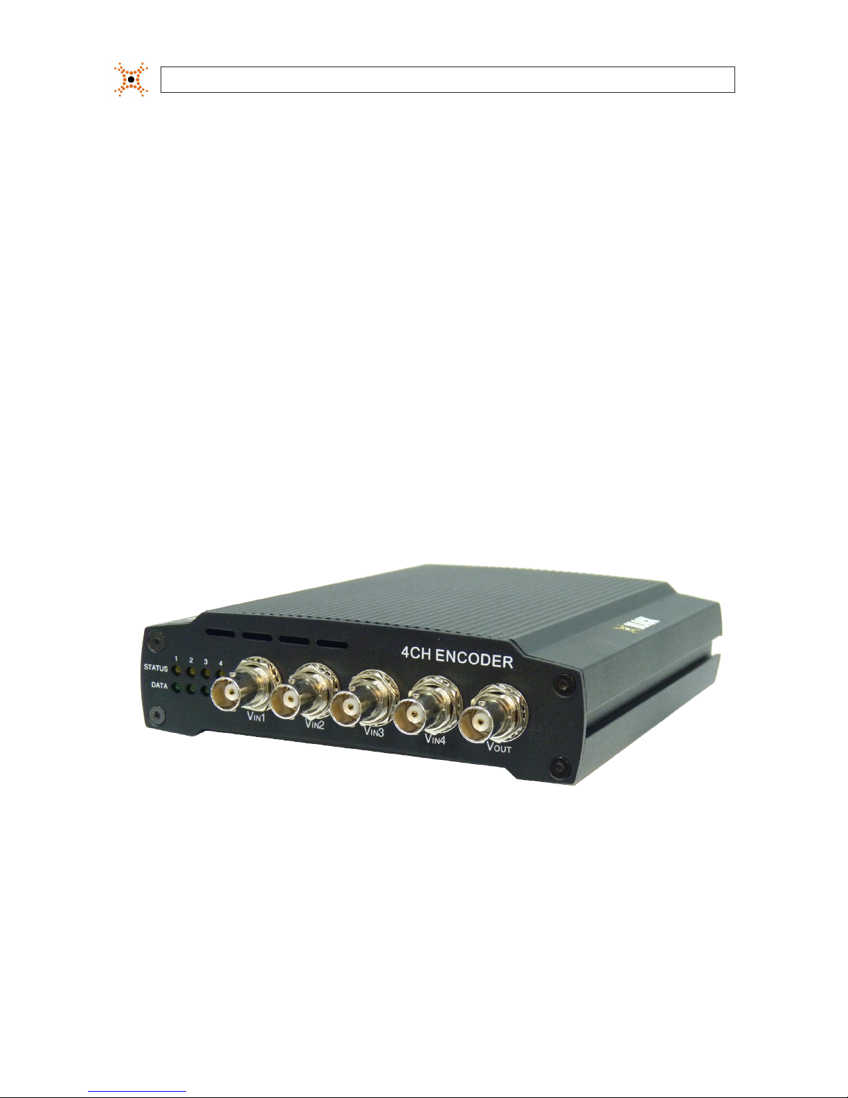
The DIGIOP™Black BLK-IPE4101 4-channel IP video encoder is a professional, premium-grade, state-of-the-art encoder designed
for indoor installation in networks where exceptional video and audio quality is required with minimal bandwidth and storage
available. Features include:
• 4-channel, H.264, MPEG-4, and MJPEG real-time encoding at D1
• 4 channel audio input, 4 channel audio output support
• Dual streaming mode with dierent codec/resolution/bit rate
• Enhanced deinterlacing on DSP
• Audio compression: G.711
• Embedded intelligent video analytics
• Burnt-in text, video motion detection support
• Remote rmware upgrade over network
• Loop-out video for external monitors
• RS-485/422 serial port for Pan/Tilt/Zoom
• RS-232C serial port
• On Screen Display (OSD) by hardware
BLK-IPE4101 Encoder
34-Channel H.264 Network Video Encoder
SECTION 1: FEATURES
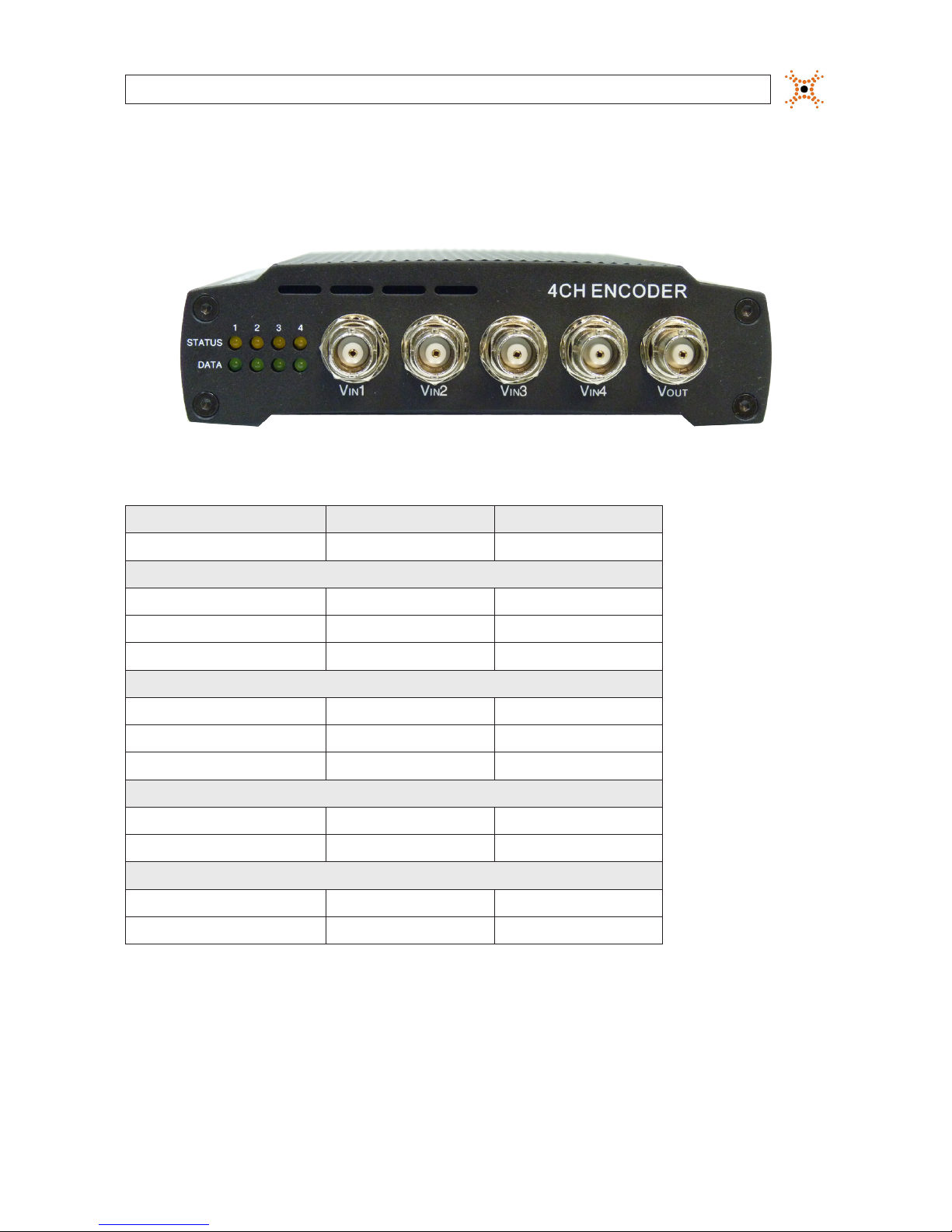
1.1 Front panel indicators and connectors
Status and Data LEDs on the front panel are provided for each IP encoder channel.
Table 1. Status and Data LEDs indications
Status Data Item
OFF OFF Power OFF
System initialization
O Blinking Dark Orange In Process
Orange O Normal State
Orange Dark Orange Abnormal State
Kernel booting up
Orange Green In Process
Orange O Normal State
Orange Green Abnormal State
Video streaming service
Blinking Green O Normal
Green O Abnormal
DSP operation status
Orange blinks at every 1 second O Normal
Orange blinks at every 1 second Red High Overload
Vin Video input BNC connector (4)
Vout For loop out of video input

4www.digiop.com
1.2 Back panel connectors
BLK-IPE4101 Encoder back panel
USB Connect to a USB device (or USB hub) for external storage.
Ethernet RJ-45 LAN connector for 10/100Base-T Ethernet.
Pin block Terminal for audio output/input (Ain, Aout, alarm out (DO), sensor in (DI), and RS-232/RS-485 serial devices
Reset Reset switch for restarting the encoder, or resetting the encoder to factory default settings.
DC12V Power adapter connector.
SECTION 1: FEATURES

54-Channel H.264 Network Video Encoder
SECTION 2: INSTALLATION AND SETUP
SECTION 2
Installation and Setup
2.1 What’s in the box
Your encoder includes the following:
• BLK-IPE4101 encoder
• 12 V DC power adapter
• 6-pin terminal blocks (2)
• 8-pin terminal blocks (2)
• Hardware installation kit including mounting brackets (2), screws (4), and wall inserts (2)
• CD mini disk with application software, software manual, and encoder user manual (this document)
2.2 Tools you need
To install the encoder, you will need:
• Phillips #2 screwdriver
• Drill 1/4” drill bit
• PC with Microsoft®Windows®XP SP3 or newer, 32- or 64-bit system
2.3 Install the encoder
1. Determine where the encoder will be mounted and record the 4 (one for each IP channel) Media Access Control (MAC)
address of the encoder. The MAC address can be found on a label on the underside of the encoder and are listed as channel 1
(top) to channel 4 (bottom). Record the information in the following table.
Location:
Channel 1 MAC address:
Channel 2 MAC address:
Channel 3 MAC address:
Channel 4 MAC address:
NOTE The Channel 1 MAC address is associated with the Vin1 analog input, Channel 2 MAC address is associated with the
Vin2 analog input, etc.
6www.digiop.com
SECTION 2: INSTALLATION AND SETUP
2. Slide the mounting brackets provided in the hardware kit into the slots on the side of the encoder.
3. Do one of the following:
—If the mounting surface is a hard material, use the 1/2” self-tapping mounting screws provided in the hardware kit to
secure the encoder to the surface.
OR
—If the mounting surface is a soft material:
i. Using the encoder with the mounting brackets as a template, mark the location of the mounting screw holes.
ii. Drill 1/4” holes in the location of the mounting screw holes for the wall inserts provided in the hardware kit.
iii. Tap the wall inserts into the holes until they are ush with the surface.
iv. Use the 1-1/8” screws provided in the hardware kit to secure the encoder to the surface.
4. Connect an analog signal source (camera video) to the Vin BNC connector on the front of the encoder.
2.4 Connections
Connections to the encoder for audio in and out (microphone Ain and speaker, Aout), sensor in (DI), alarm (DO), video out BNC,
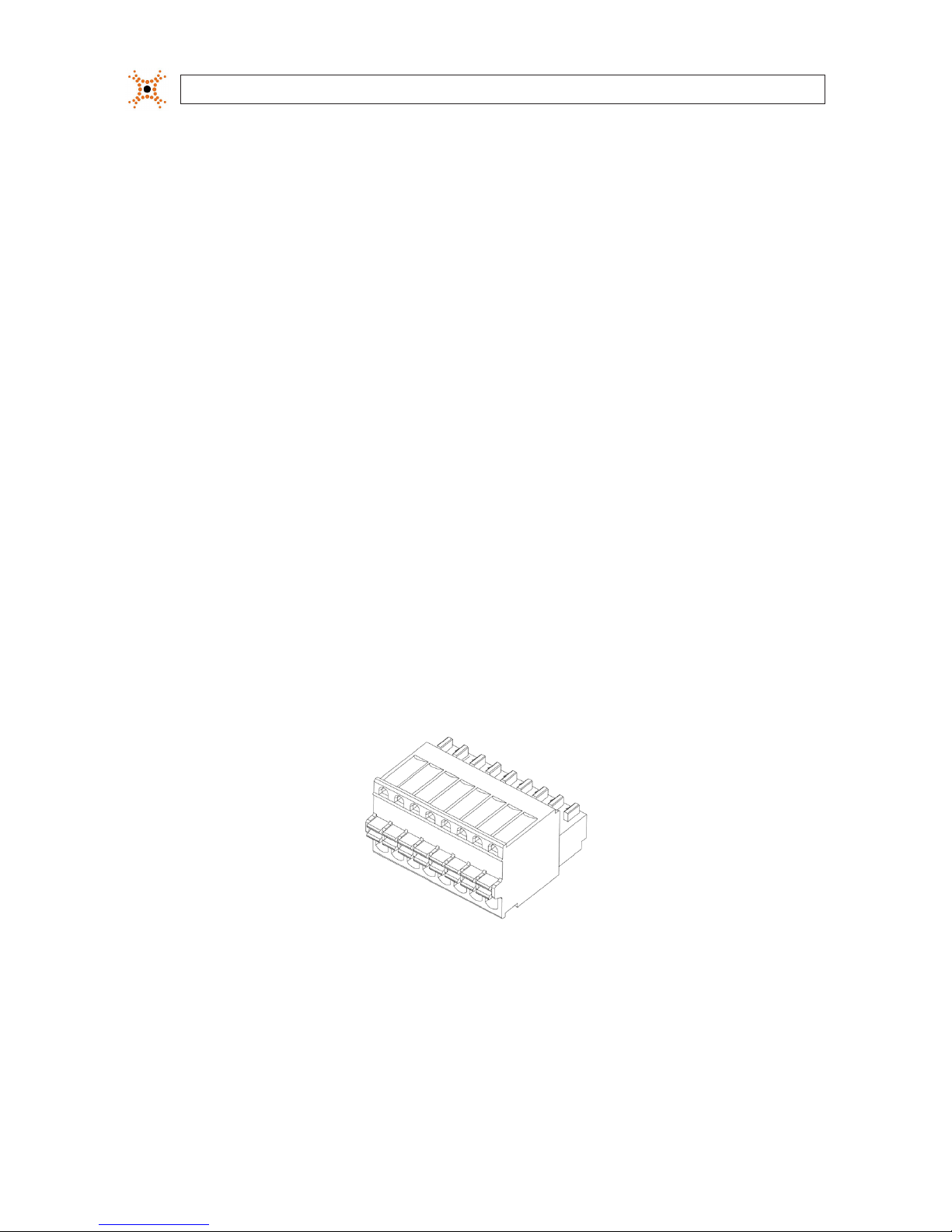
RS-232C, and RS-485 control are made through two 8-pin terminal blocks and two 6-pin terminal blocks. The terminal blocks may
be detached from the encoder. Plug the four blocks into the connectors on the back of the encoder.
8-pin terminal block

74-Channel H.264 Network Video Encoder
SECTION 2: INSTALLATION AND SETUP
Ain
Grounds Ground
Common
Aout 1 - 4 DO 1 - 4
Aout
Grounds
Ain 1 - 4 DI 1 - 4
RS-232
TX, RX, Gnd
RS-485
DATA+, DATA-, Gnd
Terminal block pin assignments
2.4.1 Audio in/out connections (Ain, Aout, channels 1 - 4)
The encoder includes an interface for a mono audio input (from a microphone) and a mono audio output (to a speaker) for each
channel. The audio output is a low level signal that requires an amplied speaker (see Specications).
To connect a speaker and/or microphone to the encoder:
1. Route speaker and/or microphone wiring to the encoder.
2. Strip 1/4” of insulation from the wires speaker signal and ground wires and insert them into the lower 6-pin terminal block
on the Aout and Aout Ground pins, respectively.
3. Strip 1/4” of insulation from the microphone signal and ground wires and insert them into the upper 6-pin terminal block on
the Ain and Ain Ground pins, respectively.
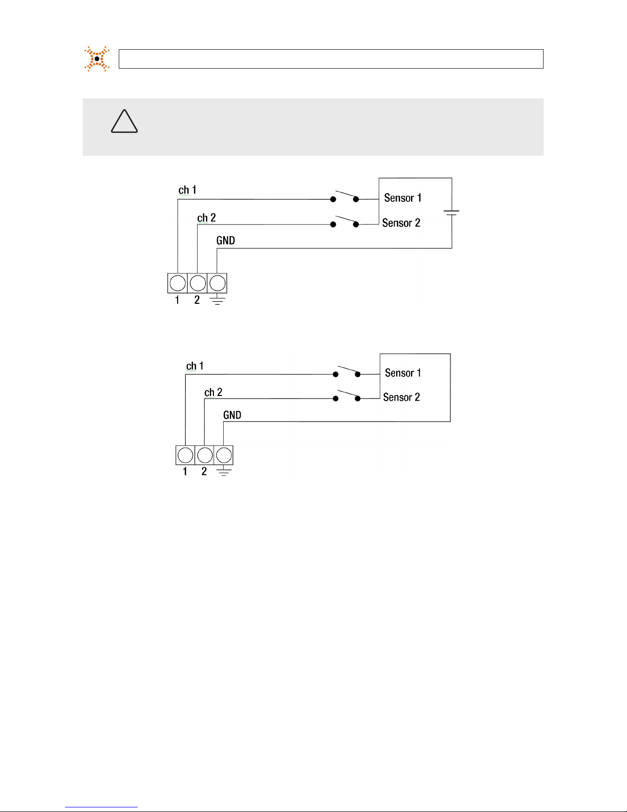
2.4.2 Sensor in connection (DI, channels 1 - 4)
The encoder provides four input channels for sensors, one for each channel. The sensors can be either all voltage or all relay type
sensors. For voltage type sensors, see Specications for allowable voltage levels. The conguration of each sensor input wiring is
illustrated in the diagrams below.
8www.digiop.com
SECTION 2: INSTALLATION AND SETUP
CAUTION
Do not exceed the maximum input voltage or the relay switching rate. Refer to specications in this manual
for more information.
Voltage type sensor wiring schematic
Relay type sensor wiring schematic
To connect a sensor to the encoder:
1. Route sensor wiring to the encoder.
2. Strip 1/4” of insulation from one sensor’s sense and ground wires and insert them into the upper 8-pin terminal block in the
DI (for channel 1, 2, 3, or 4) and DI Ground pin locations, respectively.
3. Strip 1/4” of insulation from another sensor’s sense and ground wires and insert them into the upper 8-pin terminal block in
the Ground pin locations, respectively.
2.4.3 Digital out (DO) connection
The encoder supports up to four digital out connections to reporting devices in the conguration shown in the schematic below.

94-Channel H.264 Network Video Encoder
SECTION 2: INSTALLATION AND SETUP
Digital out wiring schematic
To connect digital out reporting device to the encoder:
1. Route leads from the digital out devices to the encoder.
2. Strip 1/4” of insulation from one device’s signal and ground wires and insert them into the lower terminal block in the DO ch
1 and DO GND pin locations, respectively.
3. Strip 1/4” of insulation from another device’s signal and ground wires and insert them into the lower terminal block in the DO
ch 2 and DO GND pin locations, respectively.
2.4.4 RS-485 device connection
The encoder provides one RS-485 interface connection. The wiring signal polarity and ground to the lower terminal block are
shown in the schematic below.
RS-485 device wiring schematic
To connect an RS-485 device wiring to the encoder:
1. Route wiring from the RS-485 device interface to the encoder.
10 www.digiop.com
SECTION 2: INSTALLATION AND SETUP
2. Strip 1/4” of insulation from DATA+, DATA-, and GND wires from the device and insert them into the lower terminal block
RS-485 D+, RS-485 D-, and RS-485 GND pins, respectively, as shown in the schematic above.
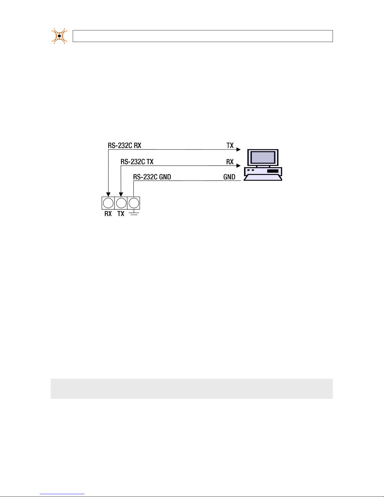
2.4.5 RS-232C device connection
The RS-232C encoder interface can be connected to some devices, such as a Point of Sale (POS) terminal. The wiring signal polarity
and ground to the upper terminal block are shown in the schematic below.
RS-232C device wiring schematic
To connect an RS-232C device wiring to the encoder:
1. Route wiring from the RS-232C device interface to the encoder.
2. Strip 1/4” of insulation from TX, RX, and GND wires from the device and insert them into the upper terminal block RS-232C
TX, RS-232C RX, and RS-232C GND pins, respectively, as shown in the schematic above.
2.4.6 LAN, video, and power connections
1. Attach the network LAN cable to the RJ-45 connector on the encoder back panel. If the encoder is powered through the LAN
cable, DO NOT apply power to the encoder at this time.
2. Attach the video stream from your camera to the Vin1, Vin2, Vin3, and Vin4 BNC connector on the front of the encoder.
NOTE Encoder Channel 1 is associated with the Vin1 analog input, Channel 2 is associated with the Vin2 analog input, etc.

114-Channel H.264 Network Video Encoder
SECTION 2: INSTALLATION AND SETUP
LAN DC12V Power
LAN and power connections
CAUTION
Overvoltage and overcurrent will cause severe damage to the encoder.
2.5 Install IPAdmin Tool
The IPAdmin Tool, included on the CD mini disk, is a utility that will discover cameras and encoders installed on your network and
enable you to perform the initial network setup for each. After a encoder is setup on the network, the Microsoft Internet Explorer®
web browser can be used to see video from the encoder, set the encoder’s password, date and time, nalize encoder hardware
adjustments, and congure the encoder for functional requirements.
The IPAdminTool can be loaded on a Microsoft Windows XP, Vista or Windows 7 operating system (32- or 64-bit). To use this utility
for the initial setup of your encoder, your computer must be connected to the same network subnet as your encoder.
At a computer on the same LAN (subnet) where your encoders will be installed, do the following:
1. Insert the CD mini disk provided with your camera into your computer’s CD ROM drive and open the CD in a Windows
Explorer window.
2. Find the IPAdminTool directory on the CD.
3. Copy the IPAdminTool directory with its contents to your computer hard drive.

12 www.digiop.com
SECTION 2: INSTALLATION AND SETUP
2.6 Congure the encoder network settings
Devices attached to a Local Area Network (LAN) are each assigned a unique address (IP address) that they use when sending
messages with each other. No two devices on a single Ethernet network can have the same IP address. Otherwise, addressing
conicts will occur.
When your IP encoder is attached to a network and initially powered on, it attempts acquire compatible network settings, for each
its four IP channels, from a DHCP server. If it cannot nd a DHCP server, it congures itself with the following static IP address,
subnet mask, and gateway setting, which may or may not be compatible with other devices on the network.
IP address: 192.168.0.100
Subnet mask: 255.255.255.0
Gateway: 192.168.0.1
Whether it acquires a dynamic (changeable) IP address and other network settings from a DHCP server, or uses the default static
(xed, unchanging) settings, your encoder must be congured with static network settings that are compatible with the network
conguration. Additionally, if DHCP is not used on your network, DIGIOP™ Black encoders must be installed on the network and
congured with new network settings one at a time to avoid addressing conicts.
Use the following procedure to setup and apply compatible, static, network settings for your encoder. If connecting your encoder to
a large enterprise network, consult with your network administrator for network settings before attaching the encoder to the LAN
to ensure that your encoder won’t conict with other devices. Your network administrator should also setup WAN (Internet) access
to the encoder, if that is needed.
If you encounter a problem and need to contact Technical Support, rst complete the chart in Table 1 about your computer (PC) and
encoder network settings, if possible. Support will need this information to provide assistance.
2.6.1 Conguring encoders on networks with DHCP
In networks with a DHCP server, the IP encoder will acquire dynamic (changeable) network settings when it is initially powered on.
These dynamic settings can easily be converted to static settings, or changed to other static settings that are also compatible with
your network.
1. Connect your encoder to the LAN, then power on the encoder.
2. Open the IPAdminTool directory on your computer, then double click the le IPAdminTool.exe to start the application.
When the IPAdmin Tool starts, it will discover all the IP devices it supports that exist on the network. The discovery process
may take a few minutes.
NOTE This 4-channel encoder will acquire four IP addresses, one for each IP interface. It will appear on the network as four separate
devices.

13H.264 Network Video Encoder
SECTION 2: INSTALLATION AND SETUP
Check the list of devices found by IPAdmin Tool. You can identify your encoder by the MAC addresses. The MAC addresses are
assigned during manufacture and can be found on the label on the underside of the unit. In this example, the IP addresses
were acquired through DHCP. The IP addresses you see with your encoder will probably be dierent from those seen above.
The Rack Info eld “M” number is directly associated with the Vin channel (M0 for Vin1, M1 for Vin2, etc.). Notice that in the
display the Rack Info identiers do you appear in order. See the following table for the example shown above.
Rack Info Vin Channel IP Address (via DHCP) MAC Address
R0, B0, M0 Vin1 192.168.5.43: 00:13:23:D4:D1:45
R0, B0, M1 Vin2 192.168.5.59 00:13:23:D4:D1:46
R0, B0, M2 Vin3 192.168.5.61 00:13:23:D4:D1:47
R0, B0, M3 Vin4 192.168.5.50 00:13:23:D4:D1:48
If an encoder channel was not found, click the Refresh button every minute until the four channels for your encoder appear
in the list.
3. In the IPAdmin Tool device list, use the encoder’s MAC addresses to nd the encoder you are installing. After nding the
encoder, right click the device for rack entry R0,B0,M0, then select IP Address from the drop-down list. An IP Setup window
will open.

14 www.digiop.com
SECTION 2: INSTALLATION AND SETUP
Static Option
4. In the IP Setup window, click the Static option bullet to select this option.
If you have other compatible network settings you want to apply to the device, enter them in the appropriate locations. Click
Setup to save settings, then click OK to conrm the change to network settings.
5. In the Login window, enter the ID and PW (password) for your encoder and click Login. The default administrator values for
the ID and PW are root and pass. After entering ID and PW, the IP Setup window closes.
6. In the IPAdmin Tool window, click Refresh and verify that the entry representing the encoder now shows the new IP
address.
7. Repeat these steps to establish a xed IP address for each encoder channel.
8. Continue with procedure 2.7 Setup encoder Basic Conguration.

15H.264 Network Video Encoder
SECTION 2: INSTALLATION AND SETUP
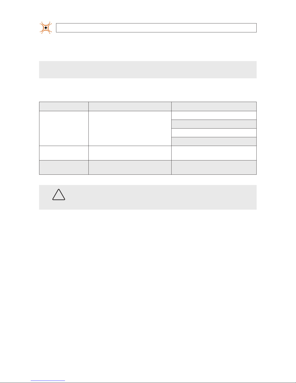
2.6.2 Conguring encoders on networks without DHCP
Encoders installed on a network without a DHCP server will initially use the factory default static network settings for each IP
channel:
IP address: 192.168.0.100
Subnet mask: 255.255.255.0
Gateway: 192.168.0.1
In networks without a DHCP server, encoders must be powered on and recongured one at a time to avoid addressing conicts
between other encoders, or possibly with another device on the network. Conguring the network settings of your encoders
includes these steps:
—Determine the network settings of your computer.
—Check the network for compatibility with the default static network settings of your encoder.
—Find four network settings (IP addresses) that are not in use and can be assigned to the IP channels of your encoder.
—Attach your encoder to the network, power it on, and congure the four IP channels with new network settings.
Determine the network settings of your computer
1. At a PC attached to the same LAN that will be shared with your encoder, determine the IP address, subnet mask, and default
gateway of your PC and record it in Table 1. To nd this information, do the following at the Windows desktop:
a. Hold down the Windows key and press rto open the Run dialog box.
b. Type cmd in the entry eld, then click OK to open the DOS command window.
c. At the command prompt, enter ipcong. The response will show the your PC’s network settings.
Example: Typical use of ipcong in Windows XP
16 www.digiop.com
SECTION 2: INSTALLATION AND SETUP
d. Enter the IP Address, Subnet Mask, and Default Gateway for your PC’s Ethernet adapter into Table 1.
NOTE The Ethernet adapter data you see by using ipcong will probably be dierent from that shown in the example above.
If you are using Windows Vista or Windows 7, the IP address is identied as the “IPv4 Address.”
Table 2. PC/Encoder network settings
Computer (PC) Encoder
IP Addresses
R0,B0,M0:
R0,B0,M1:
R0,B0,M2:
R0,B0,M3:
Subnet Mask
Default Gateway
CAUTION
If connecting your encoder to an enterprise network, consult with your network administrator for the encoder
IP addresses, subnet mask, and default gateway.
Find network settings (IP addresses) that are not in use
1. At your PC, nd an IP address on your network that is not in use:
a. Write down the EXACT IP address of your PC up to the third/last period. Using the example shown above, this
expression is: 192.168.5.
b. After the third period, include any number between 1 and 254 that is dierent from the one in your PC’s IP address, 3.
As a rst try, let’s choose 75, which will form the IP address 192.168.5.75.
c. Next, use the ping command in the DOS window to see if this IP address is in use on your network. The format of the
ping command is:
ping <IP address>
To test this IP address, enter ping 192.168.5.75. Any reply received from the ping indicates that a device on the
network is already using this IP address and you can connect to it.

174-Channel H.264 Network Video Encoder
SECTION 2: INSTALLATION AND SETUP
In the example shown above, the message “Reply from 192.168.5.75: ..” indicates that your PC can reach the
device with that IP address, and that address is in use (i.e., you cannot use it for your encoder).
d. Since the ping test of the IP address we tried showed the address was in use, try another number between 1 and 254.
For example, let’s ping 192.168.5.20. At the DOS prompt, enter: ping 192.168.5.20
e. In this test, the message “Request timed out” indicates that your PC cannot reach the device with that IP address,
and that address is probably not in use. Use this IP address for an encoder channel and enter it into Table 2 above. If
this test indicated that this IP address is in use, try other IP addresses using the steps above until an unused address is
found.
f. Repeat the steps above to nd unused IP addresses for the other three encoder channels. Enter them into Table 2.
Check LAN for default IP address compatibility
Because all DIGIOP™ Black encoders and encoders are factory congured with the static IP address 192.168.0.100, check the LAN
before connecting your encoder to ensure that network conicts with existing devices won’t occur.
At a Microsoft Windows computer attached to the LAN subnet where the encoder will be connected, open a Command Prompt
window and enter:
ping 192.168.0.100

18 www.digiop.com
SECTION 2: INSTALLATION AND SETUP
The “Request timed out” response indicates that the IP address is not in use and the encoder can be connected without causing
errors.
Attach your encoder to the network and power it on
Apply power to the encoder. When the encoder powers on, it performs an internal initialization, then establishes a connection to the
LAN. Wait until the initialization process completes before continuing. It may take up to 3 minutes for your encoder to initialize.
Congure the encoder IP address
1. Open the IPAdminTool directory on your computer, then double click the le IPAdminTool.exe to start the application.
When the IPAdmin Tool starts, it will discover all the IP devices it supports that exist on the network. The discovery process
may take a few minutes. The following window shows a typical report from an uncongured 4-channel encoder.
Check the list of devices found by IPAdmin Tool. You can identify your encoder by the MAC addresses. The MAC addresses
are assigned during manufacture and can be found on the label on the underside of the unit. In networks without DHCP, the
initial IP address of each channel is 192.168.0.100.
The Rack Info eld “M” number is directly associated with the Vin channel (M0 for Vin1, M1 for Vin2, etc.). Notice that in the
display the Rack Info identiers do you appear in order. See the following table for the example shown above.
Table of contents


