DEICO ONYX DE4001 User manual

DE4001 USER MANUAL
DEICO ONYX
USB - I²C/SPI CONVERTER

© 2023, DEICO Engineering Inc.
Ankara, Turkey
All rights reserved.
Any unauthorized reproduction, photocopy, or use of the information herein, in whole or in part,
without the prior written approval of DEICO Engineering Inc., is strictly prohibited.
These are the original instructions in English.
Document number: SBL-0038 Rev.0 2023

DE4001_USER MANUAL
Rev. No:0 Rev. Date: 05.08.2023 www.deico.com.tr 1 / 31
Contents
PREFACE.....................................................................................................................................3
Introduction to I²C .................................................................................................................3
Operation of I²C .................................................................................................................3
Introduction to SPI.................................................................................................................4
Operation of SPI.................................................................................................................4
Modes of SPI ......................................................................................................................5
Functional Description...........................................................................................................5
Features .................................................................................................................................5
Scope of Delivery ...................................................................................................................6
GETTING STARTED .....................................................................................................................7
Initial Installation ...................................................................................................................7
OPERATING BASICS....................................................................................................................7
Obtaining and Installing the Onyx Controller ........................................................................7
Selecting Additional Tasks .................................................................................................7
Installing D2XX Drivers.......................................................................................................8
Completing Onyx Controller Installation ...........................................................................9
Installation Path...................................................................................................................10
Connection Window ............................................................................................................10
Control Window...................................................................................................................11
Device Information ..........................................................................................................11
Selecting Operation Mode...............................................................................................11
I²C Control Panel ..............................................................................................................12
I²C Master Operations..................................................................................................12
Set Bit Rate...............................................................................................................13
Master Write Operation ..........................................................................................13
Master Read and Register Read Operations............................................................14
I²C Slave Operations.....................................................................................................15
SPI Control Panel..............................................................................................................15
SPI Master Operations.................................................................................................16
Set Bit Rate...............................................................................................................16
Set SPI Mode............................................................................................................17
SPI Master Exchange................................................................................................18
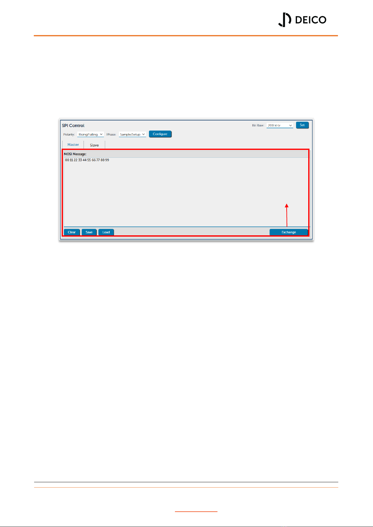
SPI Slave Operations ....................................................................................................19
GPIO Control Panel ..........................................................................................................20

DE4001_USER MANUAL
Rev. No:0 Rev. Date: 05.08.2023 www.deico.com.tr 2 / 31
Set Directions and Pull-up Mode.................................................................................21
Set Output Values and Read Values ............................................................................22
Transaction Information Panel ........................................................................................23
Log Messages...................................................................................................................24
Saved Settings and Log Messages....................................................................................25
COMPATIBILITY ........................................................................................................................25
Windows ..............................................................................................................................25
Linux.....................................................................................................................................25
HARDWARE OVERVIEW ...........................................................................................................26
Block Diagram of Onyx.........................................................................................................26
Interfaces and Connections of Onyx....................................................................................26
TROUBLESHOOTING.................................................................................................................28
Operation Information.........................................................................................................28
Device List Update ...........................................................................................................28
Transaction Message Limit ..............................................................................................28
Simultaneous Master/Slave Operations..........................................................................28
I²C Pins as GPIO................................................................................................................28
Known Issues and Limitations..............................................................................................28
I²C/SPI Master Read Operations are not Operational when Count of Bytes Requested is
Greater than 2048 Bytes..................................................................................................28
I²C Master Bit Rate Limitation .........................................................................................28
SPI Master Bit Rate Limitation .........................................................................................28
Code is Blocked at Read or Write Operations .................................................................29
Multiple Device Connection Blocks Code ........................................................................29
Multiple Device Connected to PC Crashes Application ...................................................29
SAFETY GUIDELINES .................................................................................................................29
WARRANTY...............................................................................................................................29
DE4001_USER MANUAL
Rev. No:0 Rev. Date: 05.08.2023 www.deico.com.tr 3 / 31
PREFACE
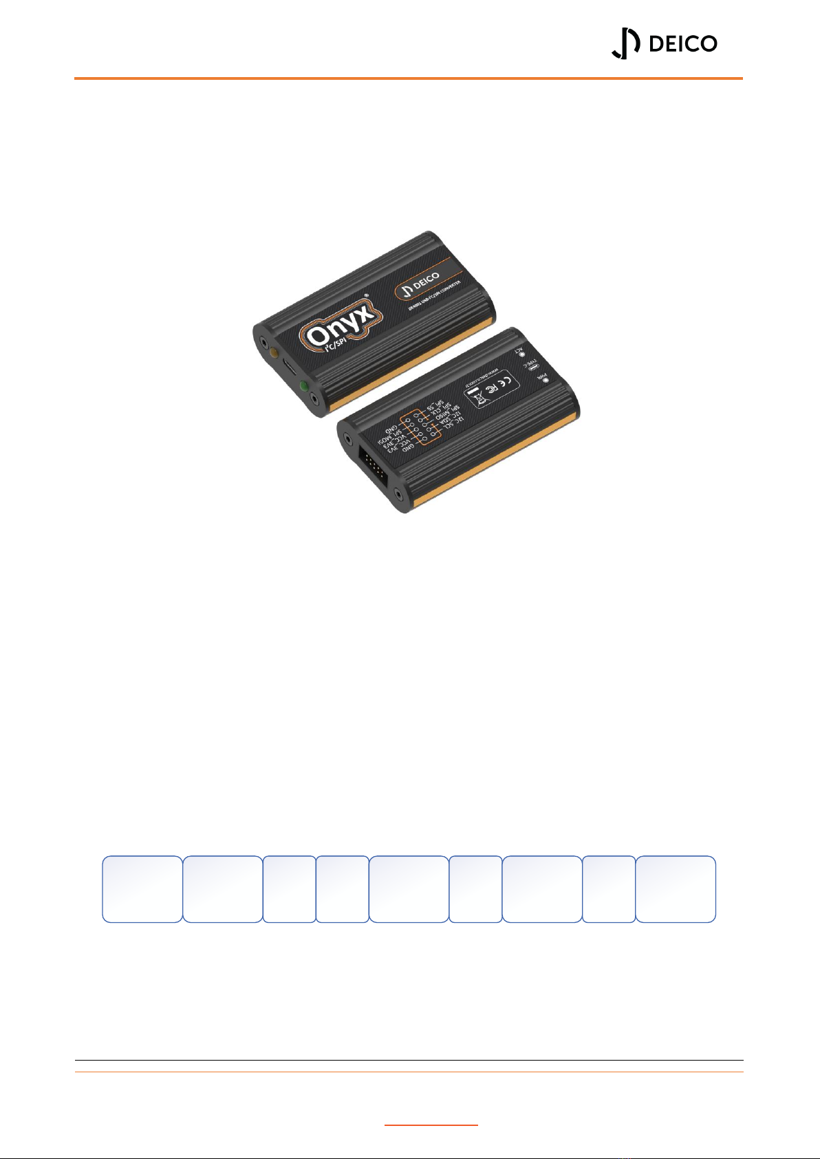
This manual describes the usage of Onyx USB I²C/SPI Converter and graphical user interface
(GUI). Onyx I²C/SPI Adapter can be controlled using the provided graphical user interface
(GUI).
Figure 1: Onyx USB-I²C/SPI Converter
Introduction to I²C
Inter-Integrated Circuit (I²C) is a synchronous serial communication protocol. All devices are
connected via 2-wires that are Serial Data (SDA) and Serial Clock (SCL). I²C has a master/slave
protocol and it supports multi master and multi slave operations. Every slave device has its
own unique address.
Operation of I²C
In I²C, data is transferred by message. Messages are broken up into frames. Each message has
an address frame and one or more data frame. Messages have also start bit, stop bit,
read/write bit and ack/nack bits. Message frame is shown in Figure 2 and sample bitstream is
shown in Figure 3.
Figure 2: Message frame of I²C
Start Condition: SDA line switches from high to low before SCL line switches from high
to low.
Address Frame: The address frame is always first in any new communication
sequence. Each slave has a 7 or 10 bit unique address.
START
CONDITION
7 OR 10 BIT
SLAVE
ADDRESS
READ/
WRITE
BIT
ACK/
NACK
BIT
8 BIT DATA
FRAME
ACK/
NACK
BIT
8 BIT DATA
FRAME
ACK/
NACK
BIT
STOP
CONDITION

DE4001_USER MANUAL
Rev. No:0 Rev. Date: 05.08.2023 www.deico.com.tr 4 / 31
ACK/NACK BIT: Each frame is followed by an ACK/NACK bit. If a frame was successfully
received, an ACK (0) bit is returned to sender from receiving device.
Read/Write Bit: Read/Write bit indicates the read (1) or write (0) operation.
Data Frames: Data frame is always 8 bits and sends the MSB first. After all data frames
are sent, master sends a stop condition to slave.
Stop Condition: SDA line switches from low to high after SCL line switches from low
to high.
Figure 3: Sample bitstream of I²C
Table 1: Specs of I²C
Specification
Value
Wires Used
2
Maximum Speed
3.4Mbps
Max Master
Unlimited
Max Slave
1008
Introduction to SPI
Serial Peripheral Interface (SPI) is a synchronous serial communication. SPI devices are
connected via 4-wires that Master Output/Slave Input (MOSI), Master Input/Slave Output
(MISO), Slave Select (SS) and Clock (SCLK). SPI has a master/slave protocol and it support multi
slave operations.
Operation of SPI
SCLK, MOSI and MISO are shared by all devices on SPI Bus. Each slave device has its own SS
line. Master device generates the clock. When data is sent from master to a slave, it is sent
via MOSI. When data is sent from slave to master, it is sent via MISO. The master chooses
which slave it wants to talk to by setting the slave’s SS line to low. In idle state, the SS line is
kept at high.
Table 2: Specs of SPI
Specification
Value
Wires Used
4
Maximum Speed
10Mbps
Max Master
1
Max Slave
Unlimited*
*In practice, the number of slaves is limited by the load capacitance of the system, which reduces the ability of
the master to accurately switch between voltage levels.
A6 A5 A4 A2 A1 A0 R/W
A3 D7 D6 D5 D4 D3 D2 D1 D0
ACK ACK Stop
Condition
Start
Condition
DE4001_USER MANUAL
Rev. No:0 Rev. Date: 05.08.2023 www.deico.com.tr 5 / 31
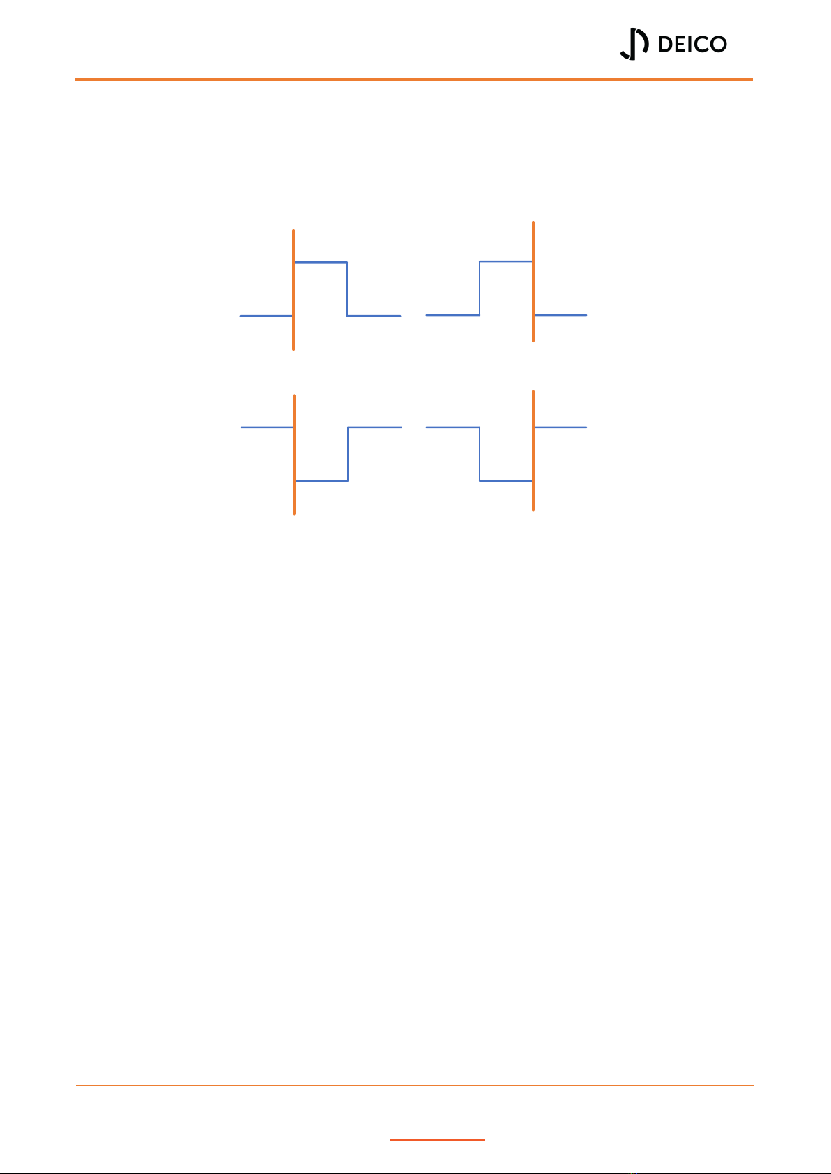
Modes of SPI
In SPI, the main can select clock polarity (CPOL) and clock phase (CPHA). Both parameters
have two states which results in four possible modes. These combinations are shown in Figure
4.
Figure 4: Modes of SPI
Functional Description
Onyx USB-I²C/SPI Converter connects a PC to an embedded or a generic device which uses
the I²C/SPI protocol via USB. Onyx USB-I²C/SPI Converter can be used as master or slave for
I²C and SPI. I²C and SPI pins can also be used as GPIO or combined with I²C or SPI functionality.
Onyx USB-I²C/SPI Converter is powered directly from the PC’s USB port.
Features
Plug and play with DEICO Serial Center
USB powered
Master or slave mode
I²C interface speeds up to 3.4MHz
I²C interface multi-master mode support
I²C interface internal pull-up resistors
SPI interface speeds up to 25MHz
Full duplex SPI interface
SPI interface software configurable slave select polarity
Configurable I²C and SPI pins as GPIO or combined with I²C or SPI
MODE 0 MODE 1
MODE 3
MODE 2
CLK IDLE
LOW
CLK IDLE
LOW
CLK IDLE
HIGH
CLK IDLE
HIGH
Sampling
Edge
Sampling
Edge
Sampling
Edge
Sampling
Edge

DE4001_USER MANUAL
Rev. No:0 Rev. Date: 05.08.2023 www.deico.com.tr 6 / 31
Scope of Delivery
DEICO Onyx USB I²C/SPI Converter supplied with the following components.
DEICO Onyx USB I²C/SPI Converter (Figure 5)
USB type-A to type-C cable (Figure 6)
225mm 10 position socket to female pin cable (Figure 7)
152.4mm 10 position female socket to socket cable (Figure 8)
Figure 5: DEICO Onyx USB I²C/SPI Converter
Figure 6: USB type-A to type-C cable
Figure 7: Female socket to pin cable
Figure 8: Female socket to socket cable
DE4001_USER MANUAL
Rev. No:0 Rev. Date: 05.08.2023 www.deico.com.tr 7 / 31
GETTING STARTED
Initial Installation
Onyx target connector (Figure 38) connections must be connected to target device. USB cable
type-C side (Figure 6) must be connected to Onyx type-C connector (Figure 39). USB-A side
must be connected to a PC. After all these connections is done, Onyx will be ready to use.
OPERATING BASICS
Obtaining and Installing the Onyx Controller
A setup file will be provided along with the Onyx I²C/SPI Adapter to install the Onyx Controller
application. Following steps shows the installation process by using the setup file.
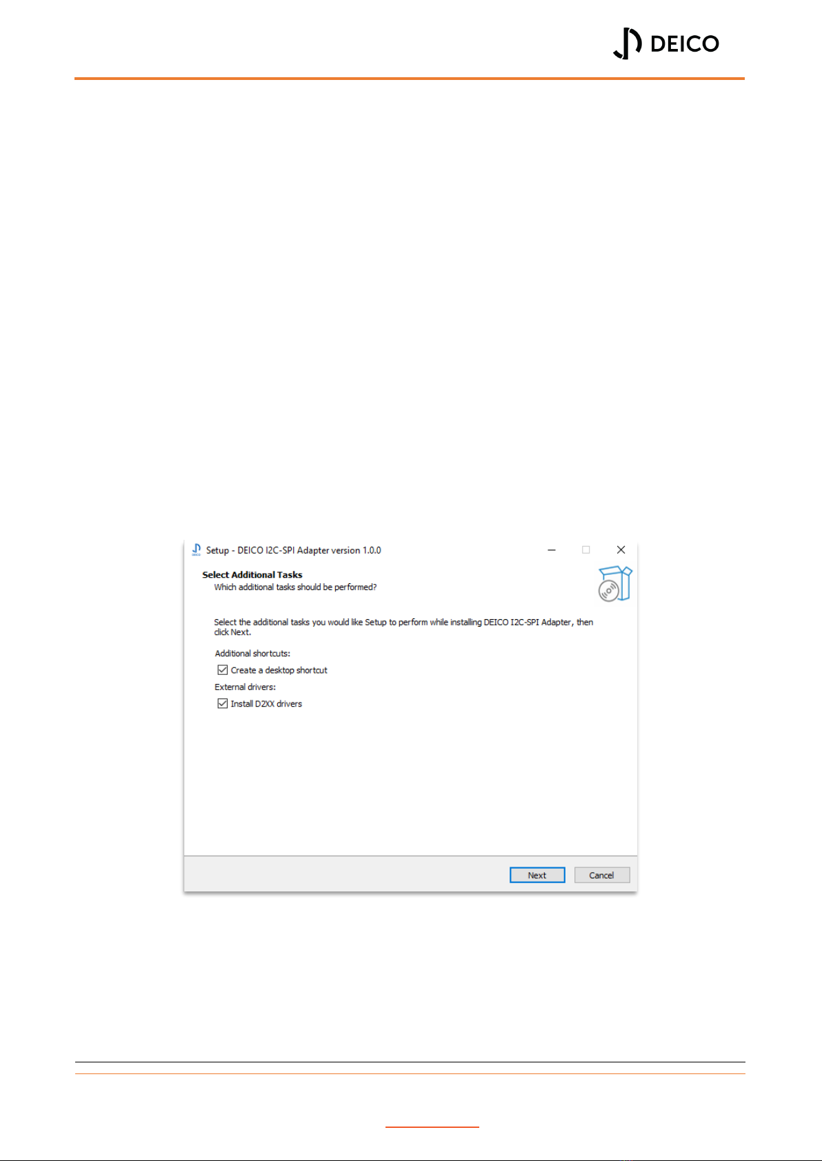
Selecting Additional Tasks
At first step, user is prompted to select additional tasks. These tasks are creating a desktop
shortcut and installing D2XX drivers. If user wants to create a desktop shortcut, this option
must be selected. Other option is used to install the D2XX drivers. If the drivers are not already
installed, user can install drivers by selecting this option.
Figure 9: Setup - Selecting additional tasks

DE4001_USER MANUAL
Rev. No:0 Rev. Date: 05.08.2023 www.deico.com.tr 8 / 31
Installing D2XX Drivers
After following the next steps, installation starts. If user selects the option “Install D2XX
Drivers”, another installation window automatically appears to install the drivers.
Figure 10: Setup - Installing drivers
To complete driver installation, user should click to extract and proceed to installation. Driver
installation wizard asks user to agree to license agreement. After this step, driver installation
is completed.
Figure 11: Setup - Completing driver installation


DE4001_USER MANUAL
Rev. No:0 Rev. Date: 05.08.2023 www.deico.com.tr 10 / 31
Installation Path
Default installation path for 64-bit application is “C:\Program Files\”. Currently users cannot
change the installation path.
Connection Window
When the application is started, connection window will appear. Onyx devices connected to
the user’s computer will be shown in this window.
User should use the “Refresh” button to update the list if a new device is connected to the
computer because device list is not updated automatically.
Figure 13: Connection window
Device description, ID number, serial number and device status are displayed in the device
list. User can use the “Connect” button to open the device.
DE4001_USER MANUAL
Rev. No:0 Rev. Date: 05.08.2023 www.deico.com.tr 11 / 31
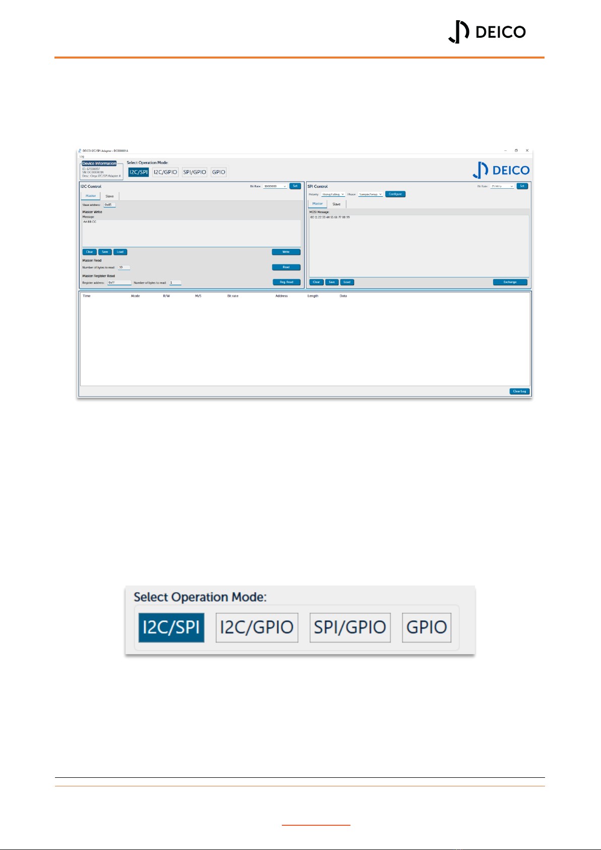
Control Window
Control window appears when user opens a device. This window contains all the functionality
to control the Onyx I²C/SPI Adapter.
Figure 14: Control window
Device Information
Device information is shown in the upper left corner of the control window. User can check
the connected device’s description, ID and serial number.
Selecting Operation Mode
Right next to the device information there is a control for selecting the operation mode. There
are four operation modes of Onyx I²C/SPI Adapter, which are I²C/SPI, I²C/GPIO, SPI/GPIO and
GPIO modes.
Figure 15: Selecting operation mode
DE4001_USER MANUAL
Rev. No:0 Rev. Date: 05.08.2023 www.deico.com.tr 12 / 31
Controls displayed on the UI are changed automatically whenever the operation mode is
changed. Users can select the operation mode according to their needs. For example, if user
needs both I²C and SPI controls, I²C/SPI mode should be selected, if GPIO pins are needed
along with SPI, SPI/GPIO mode should be selected.
Note There are six operational pins on the Onyx device, two for I²C and four for SPI.
GPIO pins are configured according to the operation mode. Pins of communication
protocol that is not selected are configured as GPIO for I²C/GPIO and SPI/GPIO pins.
For example, in I²C/GPIO mode, SPI pins are configured as GPIO pins. In the GPIO
mode, all pins are configured as GPIO pins.
I²C Control Panel
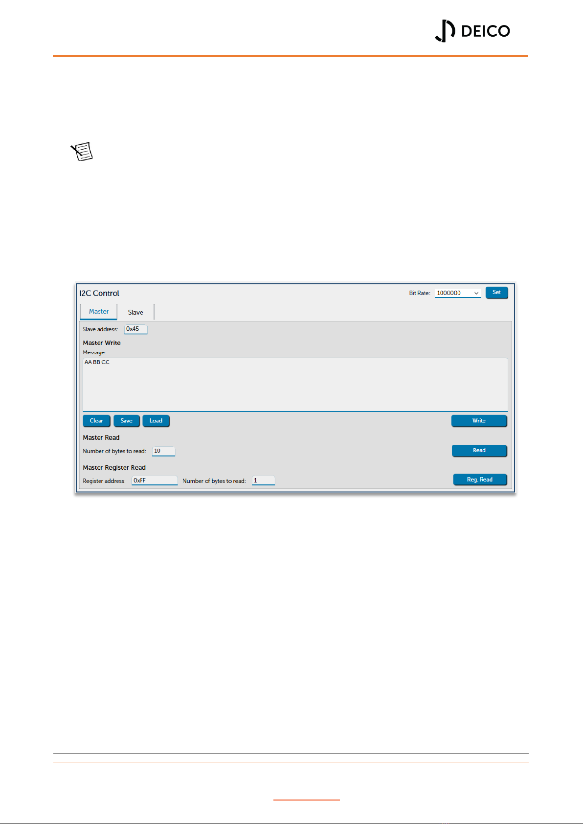
When user selects any operation mode with I²C enabled, I²C Control panel is displayed.
Figure 16: I²C control panel
There are two tabs to control the I²C, one is for master operations and the other is for the
slave operations.
I²C Master Operations
In the I²C master mode, user can:
Set bit rate
Write to a slave device
Read from a slave device
Read a register value from a slave device
DE4001_USER MANUAL
Rev. No:0 Rev. Date: 05.08.2023 www.deico.com.tr 13 / 31
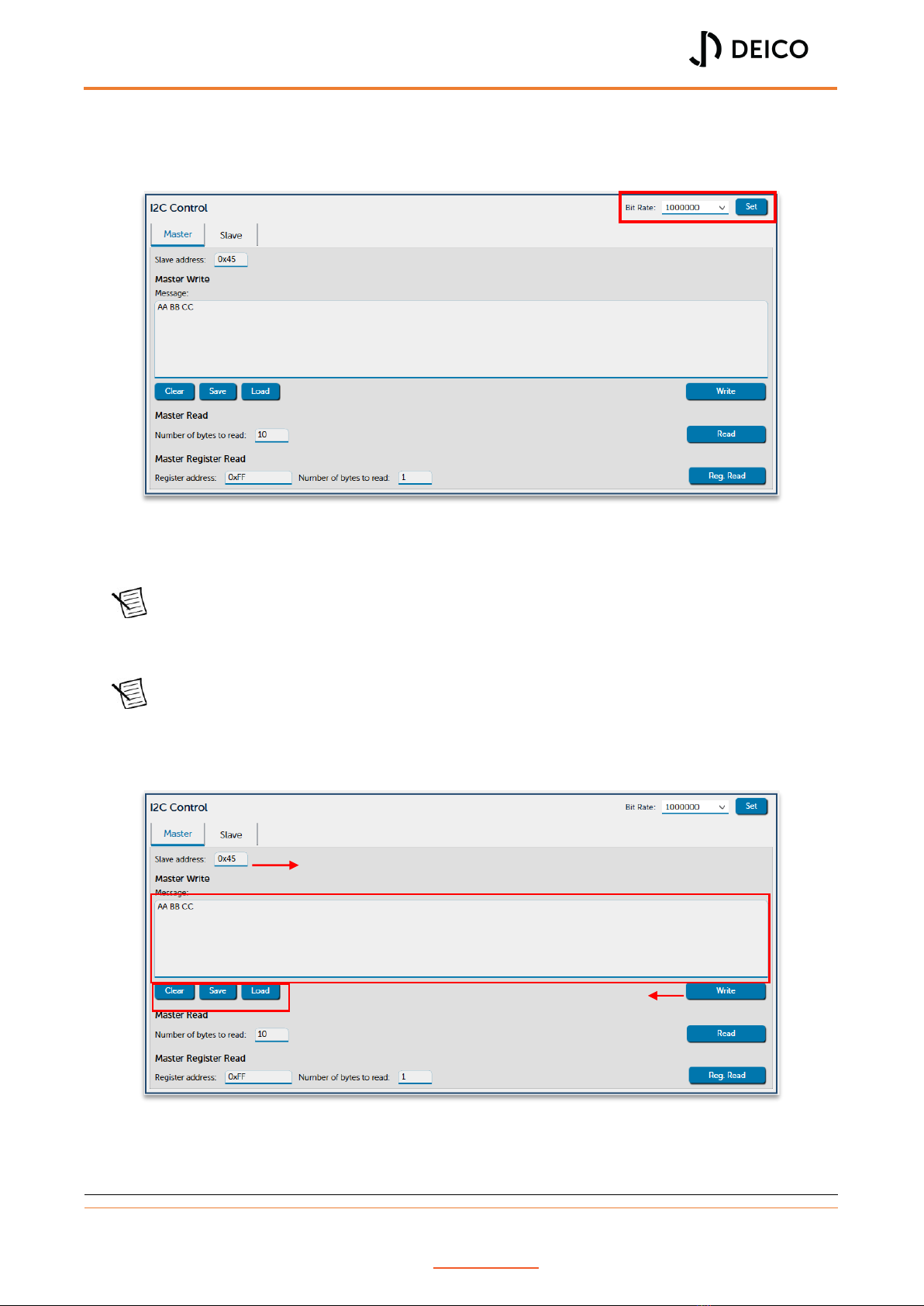
Set Bit Rate
To set the bit rate, user can select the desired bit rate and click on the “Set” button.
Figure 17: I²C master - Set bit rate
Operational bit rates are currently 100kHz, 400kHz and 1MHz.
Note Application saves the set bit rate to a settings file, see “Saved Settings and Log
Messages”for settings. However, these settings are saved to file only, if user resets
the device or powers off, bit rate must be set again to operate at the desired speed.
Note Set bit rate works for master operations only.
Master Write Operation
Figure 18: I²C master - Write operation
Slave address
Message area
Utility operations
Write button
DE4001_USER MANUAL
Rev. No:0 Rev. Date: 05.08.2023 www.deico.com.tr 14 / 31
Slave address can be set in the slave address field. This address can be written either in the
decimal format or in the hexadecimal format. In the example above slave address is set to
0x45 (69 in decimal).
Message field contains the data that will be transmitted to the slave device. This area accepts
only hexadecimal characters. Each byte is separated by a space automatically. Below this field,
there are three utility buttons that can be used to clear the data, save it to a file and load from
a file.
To transmit the data, user must click on the “Write” button.
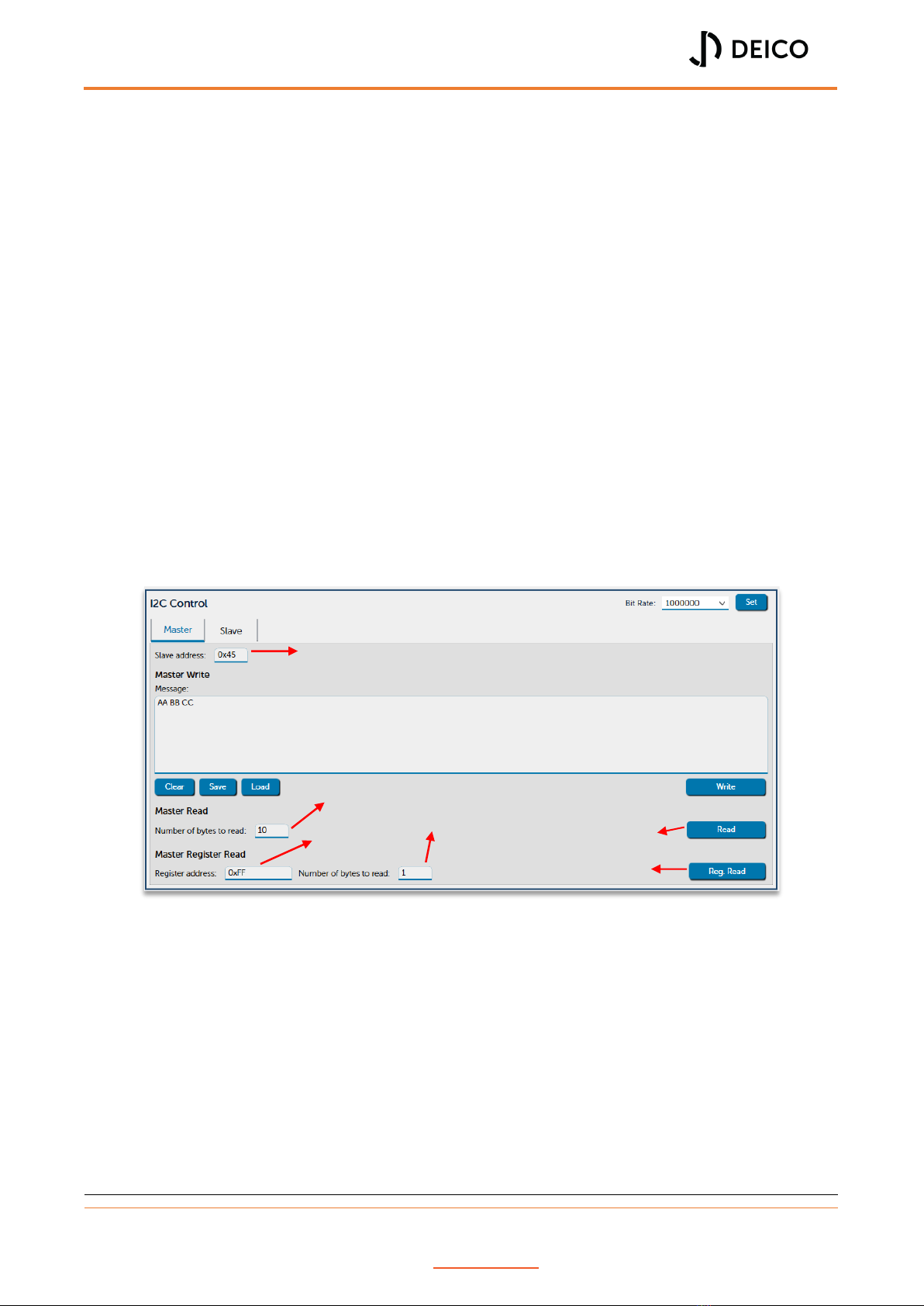
Master Read and Register Read Operations
Slave address can be as explained in the master write operation. User must provide the
number of bytes to read and then click on the read button. Read data will be displayed on the
transaction information panel, see “Transaction Information Panel”.
Register read operation is similar to read operation. The only difference is that user must
provide a register address to read from. Then, read data will be displayed on the transaction
information panel.
Figure 19: I²C master - Read & register read operations
Slave address
Number of bytes to read
Register address
Number of bytes to read from register
Read button
Register read button

DE4001_USER MANUAL
Rev. No:0 Rev. Date: 05.08.2023 www.deico.com.tr 15 / 31
I²C Slave Operations
By selecting the “Slave” tab, I²C can be configured as a slave device. Slave address of the Onyx
I²C slave device can be entered into the slave address field.
Figure 20: I²C slave control panel
To enable the slave device, enable button must be clicked. Response of the slave device can
be set after enabling the slave device. Message area is the same as the master panel’s
message field.
While the I²C slave is enabled, any incoming data to the device will be written into the
transaction information panel.
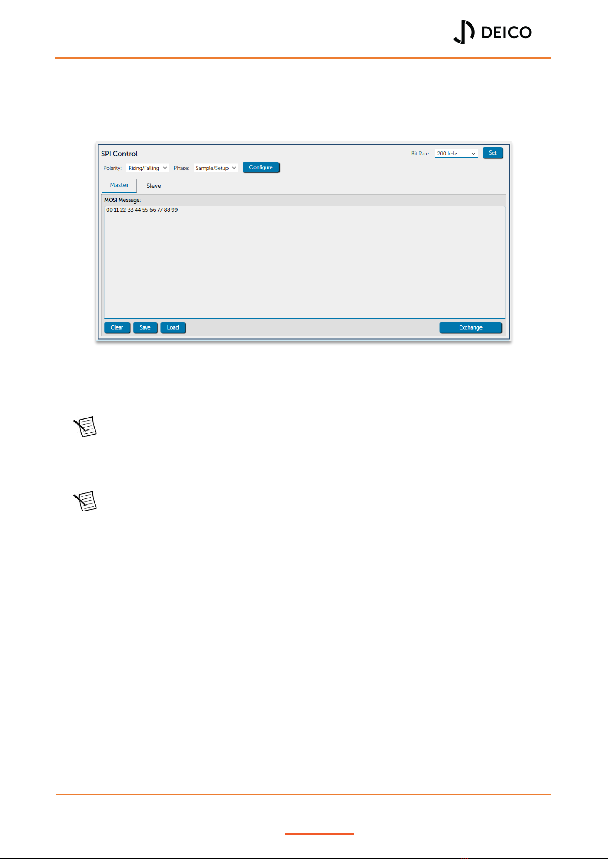
SPI Control Panel
If user selects a mode that enables the SPI, SPI control panel will be displayed. Similar to I²C
there are two tabs for master and slave operations.
Figure 21: SPI control panel
Slave address
Sets slave response
Enables slave

DE4001_USER MANUAL
Rev. No:0 Rev. Date: 05.08.2023 www.deico.com.tr 16 / 31
SPI Master Operations
In the SPI master mode, user can:
Set bit rate
Configure SPI mode
Exchange data with a slave device
Set Bit Rate
Available bit rate values for SPI are:
200kHz
400kHz
800kHz
1.6MHz
3MHz
6MHz
12MHz
25MHz
To set the bit rate, user can select the desired bit rate and click on the “Set” button.
Figure 22: SPI master - Set bit rate
Note Application saves the set bit rate to a settings file, see “Saved Settings and Log
Messages” for settings. However, these settings are saved to file only, if user resets
the device or powers off, bit rate must be set again to operate at the desired speed.
Note Set bit rate works for master operations only.
DE4001_USER MANUAL
Rev. No:0 Rev. Date: 05.08.2023 www.deico.com.tr 17 / 31
Set SPI Mode
SPI has 4 different modes. These modes can be set by setting the polarity and phase. There
are separate fields for setting the polarity and the phase.
Figure 23: SPI master - Configure modes
User can select the polarity and phase from the combo boxes. After setting the polarity and
phase, by clicking the “Configure” button, SPI configuration is sent to the device.
Note Application saves the configuration to a settings file, see “Saved Settings and Log
Messages” for settings. However, these settings are saved to file only, if user resets
the device or powers off, configuration must be set again to operate at the desired
speed.
Note Set configuration works for master operations only.
DE4001_USER MANUAL
Rev. No:0 Rev. Date: 05.08.2023 www.deico.com.tr 18 / 31
SPI Master Exchange
SPI master does not have separate controls for write and read operations. Instead, a single
exchange command exists. Similar to I²C operations, message field accepts only hexadecimal
characters. After entering data to the message field, data can be exchanged by clicking
exchange button.
Figure 24: SPI master - Exchange operation
Received data by the SPI master is shown in the transaction information panel. If user wants
to read data only, “00” bytes can be entered into the message field.
Exchanges data
Table of contents


