Brightlink BL-MOD-VW-6X20-4K User manual

User Manual
——————————————
4K Modular Video Wall Processor
2018-8

Important Safety Instructions
◆Make sure that all devices you will be connecting up are properly grounded.
◆Make sure that the power to all the devices you will be connecting up has been
turned off.
◆Do not place other objects on the cable.
◆Risk of electrical shock, do not open.
◆To avoid damaging the product, do not dismantle it by yourself, the device should be
repaired and maintained by the professional and qualified personnel in the designated
service center.
◆Do not place any object into the opening of the casing, otherwise, it might cause
voltage or short circuit incident.
◆The installation site must be well ventilated. Ensure that air vents on the equipment
are not blocked.

Contents
1 Safety Instructions............................................................................................................ - 1 -
2 About the Product..............................................................................................................- 2 -
2.1 Overview..................................................................................................................... - 2 -
2.2 Feature description....................................................................................................- 2 -
3 Installation Instruction.......................................................................................................- 4 -
3.1 Unpacking the Machine............................................................................................ - 4 -
3.2 Installation of the Machine....................................................................................... - 4 -
3.3 Machine Debugging.................................................................................................. - 4 -
3.4 Installation of the Software.......................................................................................- 4 -
3.5 Software Installation Instruction.............................................................................. - 5 -
3.6 System Topology Diagram....................................................................................... - 5 -
4 Processor Software Operation Instruction....................................................................- 6 -
4.1 Toolbar Area................................................................................................................- 6 -
4.2 Control Panel Area.................................................................................................... - 8 -
4.3 Window Operation Area..........................................................................................- 11 -
5 Detailed Description of Software Function Settings................................................. - 13 -
5.1 Equipment Management........................................................................................ - 13 -
5.2 Create a Display Wall............................................................................................. - 15 -
5.3 Create a Signal Source.......................................................................................... - 17 -
5.4 Window Operation...................................................................................................- 18 -
5.5 Layout and Scene................................................................................................... - 19 -
5.6 Peripheral Equipment Control............................................................................... - 22 -
6 Frequently Asked Questions.........................................................................................- 23 -
6.1 Unable to Access Device Through Central Management Software............... - 23 -
6.2 Improper Image Display Color.............................................................................. - 23 -
7 Factors Affecting System Performance.......................................................................- 24 -

1
Safety Instructions
1. Power supply
Please use the 220V AC power supply with single-phase three-wire and a grounding protection,
and ensure that the entire engineering system is grounded. Do not use the power supply without
grounding protection. The grounding pin of the power cable cannot be destroyed.
2. Power off
Turn off the power to ensure the safety of the equipment when moving the equipment or other
situations that require power off.
3. Cable
It is not allowed to press and place objects on cables such as power lines, signal lines, and
communication lines. Avoid trampling and squeezing the cables to prevent dangerous situations
such as leakage and short circuit.
4. Signal
Make sure that the signal wires, communication cables, etc. are connected properly, and then turn
on the power.
5. Heat dissipation
The heat dissipation holes on the surface of the device should not be blocked to avoid heat
accumulation and damage the device.
6. Environment
The working environment of the equipment should pay attention to dust, moisture and liquid
soaking.
7. Maintenance
All maintenance work should be done by a professional. Without permission, it is not allowed to
be repaired in private to avoid the risk of electric shock.
8. Equipment Installation
Equipment should be installed on a stable, stable work surface or in a standard rack, cabinet, or
chassis.
9. Safety Precautions
1) There is a high voltage in the equipment, and non-professional maintenance personnel are not
allowed to open the case to avoid danger.
2) It is strictly forbidden to place containers filled with liquid on or near the equipment.
3) Keep the equipment away from fire sources.
4) Ensure adequate ventilation, i.e., the distance of the front and rear panels of the equipment
should be at least 20cm.
5) Unplug the power cord if there is lightning or if it is not used for a long time.

2
6) Do not block the ventilation holes of this equipment to avoid damage to the equipment.
7) Do not place the device near liquids.
8) Please properly place the power cord to prevent damage.
9) Unplug the power immediately and dispose of it by a professional in the event of any of the
following conditions:
a) when the plug power cord is damaged or worn out;
b) when liquid is spilled into the device;
c) when the device is dropped or the chassis is damaged;
d) when the device has obvious functional abnormalities or performance changes.
Note: This equipment is not suitable for non-professional to operate or
debug. It must be trained or guided by professionals.
Please read this manual carefully before using this equipment. The manual
should be kept for future use.
Ⅱ. About the Product
2.1 Overview
Multi-screen image processor, also known as image processor, multi-screen splicer, etc., the main
function is to splicing multiple display units into a large ultra-high resolution logic display. On
this ultra-high resolution logic desktop, multi-picture, multi-scene arbitrary position and arbitrary
size display can be realized by window opening, and each picture can be allocated with sufficient
resolution, and the picture quality is not lost.
This series of image processors are a high-performance image splicing processing devices with
powerful pure hardware. It can display multiple dynamic RGB/VIDEO/DVI images
simultaneously in multiple display units. It is the core image processing for large-screen splicing
display system device.
2.2 Feature Description
1. The image window can be arbitrarily scaled, superimposed, and roamed in the full screen range.
More importantly, the series of processors support multiple windows to display images of the
same channel.
2. High processing power and excellent stability
The traditional image processor based on computer architecture has been developed so far. Its
performance and stability depend on the computer system it depends on. Its processing power is
improved with the improvement of computer performance, but it is limited to the serial processing
mode, and the processing speed is difficult to obtain. Quality improvement.

3
This system processor, unlike traditional design ideas, does not use a computer system, breaks the
serial data chain, and uses a high-speed parallel processing mechanism to obtain a completely new
application space.
3. Modular design of the whole machine
This series of processors adopts the design idea of modular design, and the input and output
terminals fully support hot swapping, which effectively reduces the failure rate of the equipment
and greatly improves the stability of the equipment. At the same time, in the event of a failure, the
maintenance is also simple, just replace the failed module.
4. Fast start-up, full real-time processing
This series of image processors uses a large-scale FPGA display combination processing
architecture, full hardware design, no CPU and operating system. The processor integrates
high-end image processing technology such as ultra-wideband video signal acquisition, real-time
high-resolution digital image processing, and two-dimensional high-order digital filtering, and has
powerful processing capabilities. The processor adopts multi-bus parallel processing mechanism,
which can fundamentally guarantee full real-time processing of all input video, no delay of image,
no frame loss phenomenon。
5. Support multiple signal formats
Support multiple video input modes, support multiple output modes, including HDMI, DVI
output.
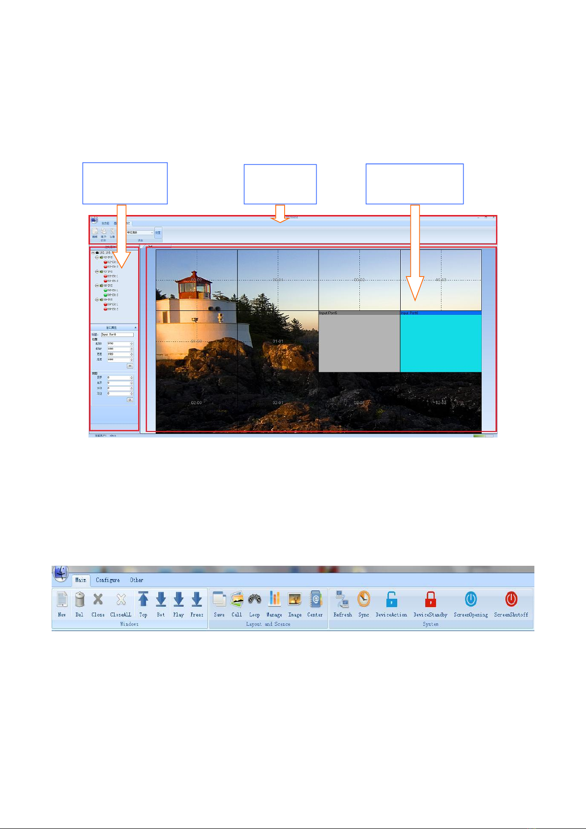
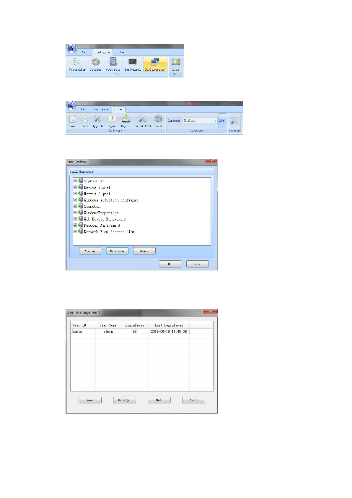
6. Multiple control methods
This series of image processor uses a variety of control methods, RS232 serial port and Ethernet
remote control.
7. Pure hardware architecture
The image processor is a pure hardware architecture, the hardware core is a large-scale FPGA
display, and there are no conventional computer accessories such as CPU, hard disk, and memory.
The system adopts a modular design, and the number of modules increases or decreases with the
number of input and output signals. A hardware-only processor, which is not a computer itself, but
a professional image processing device, and the card-based splicer based on the industrial
computer has a fundamental difference in the system.

4
8. High security performance
The image processor has no operating system, the virus can not be infected; full parallel work, no
system overall crash risk; system data has been solidified before leaving the factory, can not be
changed, unexpected power failure will not cause data loss, the processor can withstand frequent
switching. The security and stability of the industrial computer card splicer depends on the
installed software operating system.
Ⅲ. Installation Instruction
3.1 Unpacking the Machine
Check the host and accessories. Including host, power cord, network cable\serial cable, manual.
Video wall
processor Software disc
Cable User Manual
Power cable
3.2 Installation of the Machine
Insert the power cable into the power connector on the rear of the chassis and follow the logo
on the rear of the machine to access the signal. The connected output device is accurately
connected according to the output identifier, and the numbering sequence is from left to right,
from top to bottom.
3.3 Machine Debugging
Turn on the power switch, start the device, and debug it using network or serial port control.
3.4 Installation of the software
The minimum computer configuration requirements are as follows:
Standard PC, CPU min. Pentium IV
Min. 50GB free hard disk space
Min. 2GB RAM
Microsoft® Windows XP SP3 or higher

5
One Ethernet Interface
Min. screen size 17" TFT LCD
CD-ROM drive
3.5 Software Installation Instruction
The product control software is a green free installation version. Insert the CD into the CD-ROM
drive, open the file on the CD, and then copy the package to the computer. The extracted file can
be used. Find VWMS.exe in the directory.
Double-click the running software, you can also send shortcuts to the desktop for
easy use.
3.6 System topology diagram
Input signal
Output signal

6
Ⅳ.Processor Software Operation Instruction
The software can be divided into three main areas from the function, respectively, for the Control
Panel area, toolbar area, window operation area, each functional area division of efforts to
complete the multi-screen splicing processor of various functional operations.
。
4.1 Toolbar Area
including the following options
4.1.1Main function
Click this button to enter a variety of basic operations. This includes window operations, scene
settings, System refresh, and synchronization.
Please refer to the window operation for details
4.1.2Configuration
Click this button to enter the various configuration features and accessibility features of the system
Toolbar
area
Control
Panel area
Window
operation area

7
4.1.3Others
Click this button to enter the configuration of the software
4.1.3.1Panel
Under administrator privileges, add features from the Panel to『the Control Panel area』as needed
4.1.3.2 User
Under administrator privileges, add features from the Panel to『the Control Panel area』as needed。
Users and passwords that can be added, modified, and removed from user permissions. The
management list shows the current logged-in user type and the number of landings, the last time

8
the login was logged.
4.1.3.3 Registered
After you have been authorized, you can view the permissions and time of registration.
4.1.3.4 Language Settings
Select the type of language you want, click the Settings button, restart the software to take effect.
4.2 Control Panel Area
Control Panel has five lists in total, the default Display controller signal, window properties. If
you need to add other lists, you need to add them in the『panel』.
4.2.1 Controller signal
Lists the controller input signal of the current connected device, if the corresponding signal
interface is green, indicates that there is a signal access, if the corresponding signal is red,
indicating no signal access.
Move the mouse into the corresponding controller, right-click Refresh, you can view the current
signal status in real time.
Move the mouse into the corresponding signal source, right-click, select the signal properties, you
can view and modify the properties of the input signal.
At the same time, you can drag the corresponding signal source to the window operation area, you
can do the window opening operation. Please refer to the 『shortcut window operation 』for
details.
4.2.1.1 Basic Property of Signal Source

9
The resolution, frame rate, and detailed synchronization width of the current access signal can
be viewed through the signal source properties。
4.2.1.2 Advanced Property of Signal Source
This advanced property is currently only suitable for use in VGA signal sources. This property
allows you to adjust the signal source. If the image color fades and dims, you can adjust the
brightness and contrast of the corresponding color values, or click Auto White balance.
4.2.1.3 Custom resolution
Used to recommend the resolution of the source, specifying the signal format of the input. Custom
settings can also be made if there are special resolution requirements.
4.2.2 Window Attributes

10
Move your mouse over the window in the window's action area and click on the window you want
to view. The window's title list, location, and cropped properties can be seen in the window
properties list. If you need to make precise adjustments, you can fill in the required values and
click the OK button. At this time, the window of the window operation area will be adjusted
accordingly.
4.2.3 signal source list
This category applies to the processor front-end access matrix and can add video to the OSD logo.
Refer to 『Creating a Signal Source』for details.
4.2.4 Matrix signal
Used to create matrix types, matrix signals, and fast window signal switching for the matrix. See
『the peripheral equipment control』for specific operations.
4.2.5 Layout management

11
Under the administrator's authority, you can create different window layouts. You can switch
between various layouts manually and quickly. Specific reference 『window layout operation』.
4.2.6 Scene management
Under the administrator's authority, you can create different window layouts. You can switch
between various layouts manually and quickly. Specific reference 『window Scene operation』.
4.3 Window operation area
Display Wall Name : Displays the name of the currently displayed wall. The name can be entered
Display wall name
Activation
Hidden window
Display window
Dividing line

12
and modified while the wall is being created. Specific reference to『create a display wall』.
Activate window : By clicking the virtual window with the mouse, you can read out various
properties of the window, and refer to the『window properties』.
Hidden window : Right click on the virtual window and select the hidden window to hide the
window on the display wall and make the virtual window translucent.
Display window : Corresponds to the hidden window.
Split line : Can be used for window size positioning. When you double-click on a virtual window,
the virtual window is tiled to the nearest dividing line outside the edge of the window.
For other operations on the window, specific reference『window operations』.

13
Ⅴ.Detailed Description of Software Function Settings
5.1Equipment Management
5.1.1 Network Settings
When using the device for the first time, you need to set the correct network address and control
the computer connection. After the settings are saved, you can log in automatically after the later
use.
If the network settings are not correct, a prompt will be displayed, click OK and proceed.
Step 1 : Confirm the connection network of the control computer. If you have already done this
step, you can skip to step 4 and continue.
Step 2 : Locate the network connected to the controller, right-click Properties, and double-click
TCP/IPv4.
Step 3 : Modify the corresponding IP address. The IP address is 192.168.xxx.xxx, and the red area
is a fixed value. Others can be set according to user needs. Click OK to leave. (Note: Cannot be
set to the address conflicting with the device IP, the default address of the device is 192.168.70.1)
Click "OK" to save the settings.

14
Step 4 : Enter the management software and select the controller button in the configuration of the
toolbar.
Step 5 : In the controller management page, if the controller IP list is blank, click the Add button
to add it.
Step 6 : Click the search button. If the network settings are correct, the device's IP address and
device ID will appear. If you can't find the device, you can try adding the known IP address
manually. Click Save and exit.

15
Step 7 :if the network is set up correctly and the device is powered on, you can see that the
online state is online. The specific situation is shown in the figure below. If you need to modify
the IP address of the device, please set it under the guidance of a professional. Repeat step 1 if the
device is still offline.
5.1.2 Multi-device settings
If the number of devices accessing screens is more than 20, or other functional requirements are
required, and more than one device is needed to connect, then multi-device settings are required.
As for multi-device Settings, they have been set in the factory. If the field environment requires
changes to the network, follow these steps.
Step 1 : connect device 1 separately and repeat the steps of network setting in 5.1.1. In step 7, set
the controller ID to 1 and set the IP address as needed;
Step 2 : connect device 2 separately and repeat the steps of network setting in 5.1.1. In step 7, set
the controller ID to 2 and set the IP address as needed, but it cannot conflict with the address of
device 1.
Step 3 : connect device 1 and device 2 at the same time and repeat the steps of 5.1.1 network
setting. and repeat the steps of network setting in 5.1.1. At this point you can see that the controller
IP shows that two devices have been added. If both devices are online, the setup is successful.
5.2 Create a display wall
5.2.1 Single device creates wall

16
For normal shipment of products, the display wall properties required by users have been set. If
there are changes, you must set the following:
Step 1 : Enter the toolbar, click the display wall button in the configuration, and enter.
Step 2 : the figure shows the existing configuration.
Step 3 : click modify or add to enter the wall configuration.
Name: customers can customize the name of the display wall.
Resolution: select the corresponding display device resolution.
Wall number: in the case of multiple walls, it needs to be modified.
Number of rows and columns: shows the number of rows and columns of the wall.
Output board: lists the available output boards for the current device, and red indicates that
channels have been used.
Unit configuration: you can drag and drop the channels in the output board over the desired
configuration channels.

17
Ascending configuration, descending configuration: convenient for customers to configure
the channel.
Apply configuration: when all output channels are configured, click apply configuration and
the system will automatically issue and save.
5.2.3 Create more wall
Step 1 : perform step 1 of 5.2.1 to create a wall for a single device. Click add to create a new
wall.
5.3 Create a signal source
If the system needs to be configured with the video matrix, or the signal source is managed,
the signal source management function is used.
Step 1 : open the source list.
Step 2 : right-click to create a category and enter the category name.
Step 3 : in the signal source list, go to the category you just created, right click to create the
category, and if you need to add a title when the source is displayed, write the displayed characters
in the title bar. If any matrix Settings are involved, turn on the matrix toggle switch. Write
protocol.
This manual suits for next models
4
Table of contents
Other Brightlink Media Converter manuals
Popular Media Converter manuals by other brands

FibroLAN
FibroLAN MSM100U User and installation guide

Digital Watchdog
Digital Watchdog Compressor DW-ENHD16 user manual

Aurora Multimedia
Aurora Multimedia DIDO Jr. installation manual

IMC Networks
IMC Networks MediaConverter/1 Operation manual

Masibus
Masibus 9000L Series manual

ProofVision
ProofVision PV16BT Quick reference guide