4Unidrive M200 / M201 Quick Start Guide
Issue Number: 1
6 Running the motor
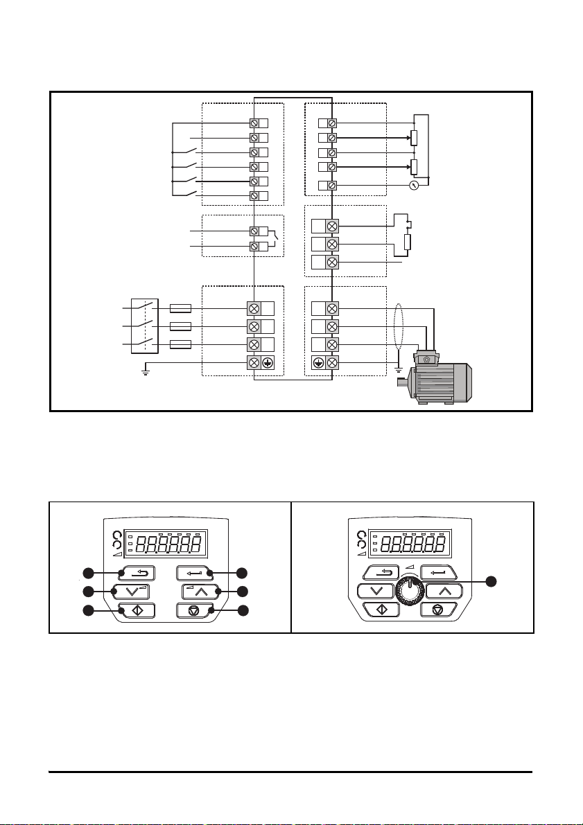
This section takes a new user through all the essential steps to running a motor for the first time. Section 4
provides the minimum connections required to connect and run a motor. The most commonly used
parameters are shown on the terminal cover of the drive.
0478-0038-01
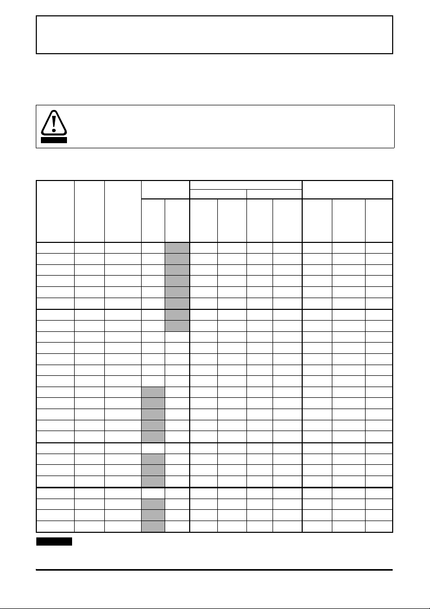
Action Detail
Before power up
Ensure:
• The drive enable signal is not given, terminal 11 is open
• The run signal is not given, terminal 12/13 is open
• The motor is connected to the drive
• The motor connection is correct for the drive Δor Y
• The correct supply voltage is connected to the drive
Power up the drive Ensure:
• The drive displays: Inh
Enter minimum and
maximum speeds
Enter:
• Minimum speed Pr 00.001 (Hz)
• Maximum speed Pr 00.002 (Hz)
Enter accel and
decel rates
Enter:
• Acceleration rate Pr 00.003 (s/100 Hz)
• Deceleration rate Pr 00.004 (s/100 Hz)
Enter motor
nameplate details
Enter:
• Motor rated current in Pr 00.006 (A)
• Motor rated speed in Pr 00.007 (rpm)
• Motor rated voltage in Pr 00.008 (V)
• Motor rated power factor in Pr 00.009
• If the motor is not a standard 50/60 Hz motor, set Pr 00.039
accordingly
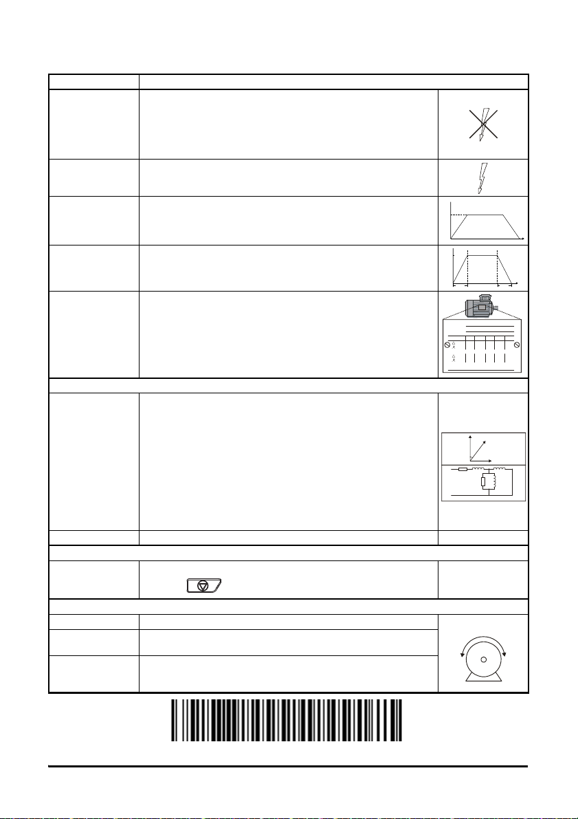
Ready to autotune
Autotune
The drive is able to perform either a stationary or a rotating autotune.
The motor must be at a standstill before an autotune is enabled.
To perform an autotune:
•SetPr00.038 = 1 for a stationary autotune or set Pr 00.038 = 2
for a rotating autotune
• Close the drive enable signal (terminal 11). The drive will display
’Rdy’.
• Close the run signal (terminal 12 or 13). The lower display will
flash ’tune’ while the drive is performing the autotune.
• Wait for the drive to display ‘Inh’ and for the motor to come to a
standstill.
• Remove the drive enable and run signal from the drive.
Autotune complete
When the autotune has been completed,
Pr
00.038
will be set to 0
Save parameters
Save parameters
Select ‘SAVE’ in Pr mm.000 (alternatively enter a value of 1000) and
press the Stop / Reset button to save parameters.
Ready to run
Run The drive is now ready to run the motor.
Increasing and
decreasing speed
Turning the speed potentiometer will increase and decrease the
speed of the motor.
Stopping
To stop the motor under ramp control, open either the run forward or
run reverse terminal. If the enable terminal is opened while the motor
is running, the motor will coast to a stop.
Mot X XXXXXXXXX
No XXXXXXXXXX kg
IP55 I.cl F C 40 s S1
°
VHzmin
-1
kW cos
φ
A
230
400
50 1445 2.20 0.80 8.50
4.90
CN = 14.5Nm
240
415
50 1445 2.20 0.76 8.50
4.90
CN = 14.4Nm
CTP- VEN 1PHASE 1=0,4 6A P=110W R.F 32MN
I.E.C 34 1(87)