manuals.online logo
Brands
  1. Home
  2. •
  3. Brands
  4. •
  5. MG
  6. •
  7. Media Converter
  8. •
  9. MG WRPPB User manual

MG WRPPB User manual

ENCODER SIGNAL DISTRIBUTOR
(rotary encoder use, BNC connection) MODEL WRPPB
BEFORE USE ....
Thank you for choosing us. Before use, please check con-
tents of the package you received as outlined below.
If you have any problems or questions with the product,
please contact our sales office or representatives.
■PACKAGE INCLUDES:
Signal conditioner (body + base socket).............................(1)
BNC cap...............................................................................(4)
(Use BNC cap to close unused I/O connector)
■MODEL NO.
Confirm Model No. marking on the product to be exactly
what you ordered.
■INSTRUCTION MANUAL
This manual describes necessary points of caution when
you use this product, including installation, connection, and
basic maintenance procedures.
POINTS OF CAUTION
■CONFORMITY WITH EU DIRECTIVES
• This equipment is suitable for Pollution Degree 2 and In-
stallation Category II (transient voltage 2500V). Rein-
forced insulation (input or output 1 or output 2 to power
input: 300V) and basic insulation (input to output 1 to
output 2: 300V) are maintained. Prior to installation,
check that the insulation class of this unit satisfies the
system requirements.
• Altitude up to 2000 meters.
• The equipment must be mounted inside a panel.
• The equipment must be installed such that appropriate
clearance and creepage distances are maintained to con-
form to CE requirements. Failure to observe these re-
quirements may invalidate the CE conformance.
• The actual installation environments such as panel con-
figurations, connected devices, connected wires, may af-
fect the protection level of this unit when it is integrated
in a panel system. The user may have to review the CE
requirements in regard to the whole system and employ
additional protective measures to ensure the CE conform-
ity.
• Install lightning surge protectors for those wires connect-
ed to remote locations.
■POWER INPUT RATING & OPERATIONAL RANGE
• Locate the power input rating marked on the product and
confirm its operational range as indicated below:
100 – 240V AC rating: 85 – 264V, 47 – 66 Hz,
approx. 4VA at 100V
approx. 5VA at 200V
approx. 6VA at 240V
24V DC rating: 24V ±10%, approx. 3W
110V DC rating: 85 – 150V, approx. 3W
■OPERATION AT THE POWER ON AND OFF
• Shortly after the power on and off, as operation is un-
stable, there may be a unwanted pulse (50msec. max.) at
output.
■GENERAL PRECAUTIONS
• Before you remove the unit from its base socket or mount
it, turn off the power supply and input signal for safety.
• If strong force is applied to the wiring for BNC connector,
the face plate comes off or being distorted. Be aware that
extraordinary force is not applied to the wiring.
■ENVIRONMENT
• Indoor use.
• When heavy dust or metal particles are present in the
air, install the unit inside a proper housing with sufficient
ventilation.
• Do not install the unit where it is subjected to continuous
vibration. Do not subject the unit to physical impact.
• Environmental temperature must be within -5 to +55°C
(23 to 131°F) with relative humidity within 30 to 90% RH
in order to ensure adequate life span and operation.
■WIRING
• Do not install cables close to noise sources (relay drive
cable, high frequency line, etc.).
• Do not bind these cables together with those in which
noises are present. Do not install them in the same duct.
■AND ....
• The unit is designed to function as soon as power is sup-
plied, however, a warm up for 10 minutes is required for
satisfying complete performance described in the data
sheet.
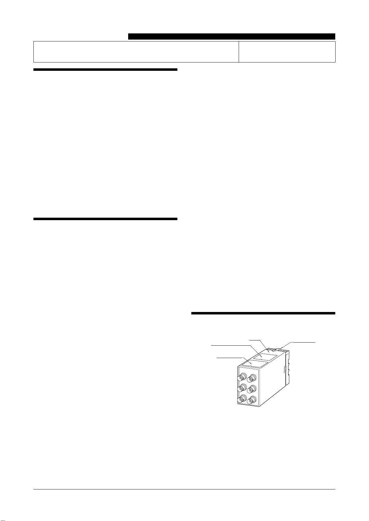
COMPONENT IDENTIFICATION
Connection Diagram
Body Base Socket
Specifications
EM-2223 Rev.4 P. 1 / 4
MG CO., LTD. www.mgco.jp
5-2-55 Minamitsumori, Nishinari-ku, Osaka 557-0063 JAPAN
INSTRUCTION MANUAL
INSTALLATION
Detach the yellow clamps located at the top and bottom of
the unit for separate the body from the base socket.
Clamp
(top & bottom)
DIN Rail
35mm wide
Spring Loaded
DIN Rail Adaptor
Shape and size of the base socket
are slightly different with various
socket types.
■DIN RAIL MOUNTING
Set the base socket so that its
DIN rail adaptor is at the bot-
tom. Hang the upper hook at
the rear side of base socket on
the DIN rail and push in the
lower. When removing the
socket, push down the DIN
rail adaptor utilizing a minus
screwdriver and pull.
■WALL MOUNTING
Refer to “EXTERNAL DI-
MENSIONS.”
TERMINAL CONNECTIONS
Connect the unit as in the diagram below or refer to the connection diagram on the top of the unit.
■EXTERNAL DIMENSIONS unit: mm (inch)
20
(.79)
20
(.79)
80 (3.15)
50 (1.97)
3456
2187
103 (4.06)
123 (4.84)[3.3 (.13)]
80 (3.15)
11
(0.43)
40 (1.57)
50 (1.97)
7.8 (0.31)
CLAMP
(top & bottom)
DIN RAIL
35mm wide
2–4.5 (.18) dia.
MTG HOLE
15 (.59) deep
8–M3.5
SCREW
20 (0.79)
• When mounting, no extra space is needed between units.
16 (.63)
WRPPB
EM-2223 Rev.4 P. 2 / 4
MG CO., LTD. www.mgco.jp
5-2-55 Minamitsumori, Nishinari-ku, Osaka 557-0063 JAPAN
■CONNECTION DIAGRAM
7
8
+
−
+
−
PHASE A
INPUT
OUTPUT 1
OUTPUT 2
+
−
PHASE B
PHASE A
+
−
PHASE B
+
−
+
−
U (+)
V (−)
POWER
PHASE A
PHASE B
PHASE A
PHASE B
PHASE A
PHASE B
PHASE A
PHASE B
PHASE B
PHASE A
PHASE B
PHASE A
PHASE B
PHASE A
PHASE B
PHASE A
PHASE B
PHASE A
PHASE B
[ Input Connection Examples ]
•Open Collector Output
[ Output Connection Examples ]
•Voltage Pulse Output
500Ω
•Dry Contact Input
5V
•Voltage Pulse Input
•RS-422 Line Driver Pulse Output
+
–
•RS-422 Line Driver Pulse Input
PHASE A
+
–
+
–
+
–
RS-422
Receiver
RS-422
Receiver
Rotary Encoder
Phase A
Phase A
Phase B
Phase B
FUNCTIONS & OPERATIONS
The unit is designed to isolate two phase pulse from a rotary encoder and distribute it into two outputs.
• Capable of handling voltage pulse, dry contact and RS-422 line driver pulse input signals.
• Capable of handling voltage pulse, open collector and RS-422 line driver pulse output signals.
• Kinds of signals (input, output 1 and output 2) are selectable.
• Maximum available frequency is 1 MHz. (It varies depending on kinds of signals.)
WRPPB
EM-2223 Rev.4 P. 3 / 4
MG CO., LTD. www.mgco.jp
5-2-55 Minamitsumori, Nishinari-ku, Osaka 557-0063 JAPAN
OUTPUT LOGIC
H
L
Voltage pulse
or
RS-422 line
driver pulse
Output
Non-inverted
Non-inverted
Dry contact
Input
H
L
H
L
OFF
ON
H
L
Inverted
Inverted
H
L
OFF
ON
OFF
ON
OFF
ON
OFF
ON
Open collector
Voltage pulse
RS-422 line driver pulse
CHECKING
1) Terminal wiring: Check that all cables are correctly con-
nected according to the connection diagram.
2) Power input voltage: Check voltage across the terminal
7 – 8 with a multimeter.
3) Input:
• Check that the frequency is within the range described
below.
Dry contact, 12 V / 24 V pulse: ≤ 100 kHz
3.3 V, RS-422 line driver pulse: ≤ 1 MHz
5 V pulse: ≤ 500 kHz
And also, check that it doesn’t exceed the maximum fre-
quency of output signal.
• When operating at frequencies close to the maximum fre-
quency, use pulse duty at approx. 50%.
4) Output: Check that the load voltage meets the specifica-
tions described in the table below.
OUTPUT SIGNAL LOAD VOLTAGE
Open Collector 50 V DC ≤ 100 mA
Voltage Pulse
(except 12 V pulse)
Equivalent value same as output
impedance
12 V pulse ≥ 600 Ω
5) Open the front cover to check the input pulse status with
monitor LEDs.
Phase A: Green, Phase B: Red, Input low: LED on
(LED on/off is not defined at input opened.)
■FRONT VIEW
IN A
INPUT
MONITOR
OUT 1A
OUT 2A
IN B
OUT 1B
OUT 2B
A
BInput Monitor LED
Phase A (Green)
Input Monitor LED
Phase B (Red)
Input Phase B
Output 1 Phase B
Output 2 Phase B
Input Phase A
Output 1 Phase A
Output 2 Phase A
LIGHTNING SURGE PROTECTION
We offer a series of lightning surge protector for protec-
tion against induced lightning surges. Please contact us to
choose appropriate models.
WRPPB
EM-2223 Rev.4 P. 4 / 4
MG CO., LTD. www.mgco.jp
5-2-55 Minamitsumori, Nishinari-ku, Osaka 557-0063 JAPAN

Other MG Media Converter manuals

MG KAP User manual

MG

MG KAP User manual

MG 18CE User manual

MG

MG 18CE User manual

MG 17RS User manual

MG

MG 17RS User manual

MG 17VS User manual

MG

MG 17VS User manual

MG KAPU User manual

MG

MG KAPU User manual

MG M8VS1 User manual

MG

MG M8VS1 User manual

MG 18RS User manual

MG

MG 18RS User manual

MG M80YV User manual

MG

MG M80YV User manual

MG STE02W User manual

MG

MG STE02W User manual

Popular Media Converter manuals by other brands

Data Conversion Systems DCS SCARLATTI DAC user manual

Data Conversion Systems

Data Conversion Systems DCS SCARLATTI DAC user manual

VOLKTEK IRF-633 user manual

VOLKTEK

VOLKTEK IRF-633 user manual

Afinion 1115660 user manual

Afinion

Afinion 1115660 user manual

Lindy 25115 user manual

Lindy

Lindy 25115 user manual

Feig Electronic OBID i-scan ID ISC.ANT.PS-A Mounting instructions

Feig Electronic

Feig Electronic OBID i-scan ID ISC.ANT.PS-A Mounting instructions

Axis M71 Series installation guide

Axis

Axis M71 Series installation guide

Inline IN1401 Operation manual

Inline

Inline IN1401 Operation manual

Black Iris For Telecom & Technology ETH-FE1 Data sheet & user manual

Black Iris For Telecom & Technology

Black Iris For Telecom & Technology ETH-FE1 Data sheet & user manual

Mitsubishi PAC-SJ96MA-E installation manual

Mitsubishi

Mitsubishi PAC-SJ96MA-E installation manual

DigiSender DGXDSDV112 Installation and troubleshooting guide

DigiSender

DigiSender DGXDSDV112 Installation and troubleshooting guide

KROHNE IFC 050 quick start

KROHNE

KROHNE IFC 050 quick start

Elgas miniELCOR SCR1 Operation manual

Elgas

Elgas miniELCOR SCR1 Operation manual

Snell & Wilcox Kudos Plus CVR250 Operator's manual

Snell & Wilcox

Snell & Wilcox Kudos Plus CVR250 Operator's manual

PR electronics 3101 product manual

PR electronics

PR electronics 3101 product manual

Techly IDATA DP-102 user manual

Techly

Techly IDATA DP-102 user manual

Pro-Ject Audio Systems BOX DESIGN Stream Box DS2 T instruction manual

Pro-Ject Audio Systems

Pro-Ject Audio Systems BOX DESIGN Stream Box DS2 T instruction manual

Advantech SSPBM-K125-BTE Installation and operating manual

Advantech

Advantech SSPBM-K125-BTE Installation and operating manual

Spirent Vertex VCE6-HFC-4C Setup guide

Spirent

Spirent Vertex VCE6-HFC-4C Setup guide

manuals.online logo
manuals.online logoBrands
  • About & Mission
  • Contact us
  • Privacy Policy
  • Terms and Conditions

Copyright 2025 Manuals.Online. All Rights Reserved.