Blackbird EZ-1 Classic Quadribent User manual

EZ-1 QUADRIBENT ASSEMBLY INSTRUCTIONSAND USER GUIDE
1
By Blackbird Designs Inc. and Blackbird Sales
Mark 4.1 - May 2007
EZ-1 QUADRIBENT™
Assembly Instructions
And User Guide
www.blackbirdbikes.com

EZ-1 QUADRIBENT ASSEMBLY INSTRUCTIONSAND USER GUIDE
2
FOR TECHNICAL SUPPORT CONTACT:
Blackbird Designs Inc.
Jim Black, President
12721 Appleview Lane
Burnsville, N 55337
Phone: 952-894-7705
Email: blackbirdbikes@aol.com
www.blackbirdbikes.com

EZ-1 QUADRIBENT ASSEMBLY INSTRUCTIONSAND USER GUIDE
3
General Rules For Safe Riding
1. DO NOT ALLOW ANYONE TO STAND OR SIT ON THE CARGO PLATFORM OR ANY OF THE
QUADRIBENT CONNECTING PARTS OR TO RIDE ANYWHERE EXCEPT SITTING ON THE SEAT.
2. Adults should supervise children at all times.
3. Always wear a CPSC approved helmet and some form of eye protection.
4. Always ride with a rear view mirror attached to your helmet or mounted to your vehicle.
5. Obey all traffic rules and regulations, signs and signals.
6. Ride on the side of the road, going in the same direction as the traffic.
7. Use proper hand signals when turning or stopping.
8. Be alert at all times, especially watch for cars pulling out into traffic and for opening doors.
9. Please read EZ-1 Owner’s Manual for additional information regarding “EZ-1 Riding Tips”, “Night Riding
Tips”, “Wet Weather Riding Cautions”, “Fitting Your EZ-1” and “EZ-1 Riding Tips”.
General Rules For Riding Your EZ-1 Quadribent
1. Inspect your EZ-1 Quadribentbefore every ride. Make sure all nuts and bolts on the EZ-1 and
accessory Quadribentframe are securely tightened. Check your brakes by applying them and pushing
the Quadribentforward and backward to make sure they are engaging properly. Check your tires for
proper air pressure as indicated on the sidewall of the tires. Make sure the quick release levers on the
wheels and seat are properly closed and secure. Make sure all of the Quadribentmounting hardware is
properly installed. Check to see that the quick release pins on the steering tie rod are properly inserted
and locked. Stop vehicle and discontinue riding if any mechanical problems arise, including but not
limited to any sudden changes in: vehicle stability, steering control, and / or pedaling difficulty.
2. Check and adjust your seat position/seat recline before mounting your Quadribent. Never attempt to
readjust the seat position while vehicle is in motion.
3. Always ride your Quadribentwith a partner. Never ride the Quadribent“solo” for the vehicle may lose
stability in turns and can tip over resulting in serious injury.
4. Always wear the factory supplied seat belts when riding the EZ-1 Quadribent.
5. The Co-Captain Steering links the handlebars of both EZ-1 recumbents together allowing either rider to
pilot the Quadribent. Each rider should always keep both hands on the handlebars when the vehicle is
in motion. Each rider is responsible for steering around people, vehicles and/or any obstructions to avoid
collisions with any objects in your path.
6. Remove the factory supplied “parking brake” strap after mounting the vehicle and properly securing your
seatbelt. Always reinstall the “parking brake” strap before exiting the vehicle.
7. As a courtesy to your riding partner and for the safe operation of the Quadribentboth riders should
communicate all non emergency turns, braking, starts and stops before they are executed.
8. For the safety of both riders, it is recommended the vehicle be slowed to less than 10 miles per hour
(mph) before initiating any turns of 90 or more degrees.
9. The EZ-1 Quadribentis designed for use on streets and bike paths only. Off-road, off-trail, mountain
trail and / or open field riding is not recommended and should not be attempted.
10. Do not modify, drill holes or mount accessories to Quadribentcross beams or frame.
The Quadribent is 2-seat, side-by-
side, human powered vehicle that enables almost anyone to enjoy cycling.
The 4-wheeled design maximizes stability and the recumbent position maximizes your seating com ort. Heads-
up design eliminates neck, shoulder and hand pain. Co-
Captain steering allows either rider to pilot the vehicle
and the dual-
drive allows people with di erent physical abilities to ride together with either rider generating rom
0 to 100 percent o the power. The Quadribent is great or combini
ng an adult rider with a child and/or
physically challenged rider. The Quadribent
can be separated into two recumbents bikes or “solo” riding and
easy transportation however it is not recommended to be done on a regular basis. Most people never separate it.
www.blackbirdbikes.com

EZ-1 QUADRIBENT ASSEMBLY INSTRUCTIONSAND USER GUIDE
4
HELPFUL HINTS
The EZ-1 Quadribent ™ Kit comes in three slightly di erent models. Quadkit J&B part # 67458 is
designed or the EZ-1 SC or SX (steel rame), the Quadkit AX J&B part # 67459 is designed or the EZ-1
AX (aluminum rame). A custom Quadkit or the EZ-1 Lite (aluminum rame) can be ordered rom
Blackbird Designs. Please be sure you have the compatible bikes and Quadribent™ Kit before
starting.
The EZ-1 Quadribent™ Kit is partially assembled, and is intended to be sold in a ully assembled and
adjusted condition by your Dealer. I the kit is bought ‘ actory direct’ by the customer, he is responsible
or inal assembly and adjustment.
Completely assemble two EZ-1 Recumbents per assembly instructions, but DO NOT NSTALL
SEATS until a ter the Quadribent™ Kit is completely installed.
The sequential assembly numbering system has been adjusted so that the text and pictures share the same
number.
Designate one bike as the “LEFT B KE” ( acing orward) and second bike as the “R GHT B KE”.
The remaining portion o the Instruction Manual is pictorially based. Review instructions be ore starting
to assemble Quadribent™ Kit. Simply ollow the sequence o pictures displayed on the ollowing pages.
The average assembly time is approximately 30 minutes.
The Quadribent™ Kit is manu actured to be assembled with basic hand tools. Tools recommended
include: tape measure, wrenches, socket set, and metric allen wrenches.
I questions arise or technical support is required during the assembly process, please contact Blackbird
Designs / Sales or a prompt service. The contact in ormation is listed on page 2.
Blackbird Designs / Sales recommend the replacement o the O.E.M. tires supplied with the EZ-1 SC or
SX recumbent bikes (EZ-1 Lite and EZ-1 AX come standard with 100 psi tires). We suggest installation
o high pressure Maxxis Hookworm (110 psi 16” ront and 110 psi 20” rear) tires to reduce the rolling
resistance and improve per ormance o the Quadribent. Check with your local bike shop or availability.
These tires are also available rom BlackBird Sales to dealers at special prices.
www.blackbirdbikes.com

EZ-1 QUADRIBENT ASSEMBLY INSTRUCTIONSAND USER GUIDE
5
EZ-1 QUADRIBENT™ PARTS LIST
1. FRONT BEAM (‘U’ shaped 1” x 1” square aluminum tube)
2. LOWER TUBE (1¼” x 1¼” square aluminum tube 28” long)
3. REAR AXLE BEAM (1” x 1” square aluminum tube 20” long)
4. TOP BEAM (1” x 1” square aluminum tube 29½” long)
5. FRONT BRACKETS (four aluminum plates 3” x 6½”)
6. TOP BRACKETS (for under seat) (two 3¼” x 1” formed aluminum)
7. REAR BRACKET (two aluminum angles - left hand and right hand)
8. CARGO PLATFORM (30” X 18” aluminum sheet)
9. CARGO PLATFORM SUPPORT (18” x 8” aluminum sheet)
10.STEERING LEVERS (two pairs machined 1” x ¾” aluminum bars)
11.STEERING TIEROD ASSEMBLY (28” long threaded rod with rod end bearings)
12.EZ-1 SX/SC HARDWARE KIT (one parking brake - Velcro strap, three ¼” x ¾” bolts, three ¼” x
1-½” bolts, twenty ¼” x 1-3/4” bolts, two ¼” x 2” bolts, sixty ¼” washers, twenty-eight ¼” nylock
nuts, two 5/16” x 3 ¼” bolts, four 5/16” washers, two 5/16” plastic washers, two 5/16-18 nylock
nuts, four 8mm x 45-50mm machine screws, two 6mm x 20mm screws, two 6mm x 16mm screws,
two small plastic washers, four small steel washers and two quick release pins.
13.EZ-1 AX/Lite HARDWARE KIT (one parking brake - Velcro strap, three ¼” x ¾” bolts, three ¼”
x 1-½” bolts, eight ¼” x 1-¾” bolts, fourteen ¼” x 2” bolts, sixty ¼” washers, twenty-eight ¼” nylock
nuts, two 5/16” x 3-½” bolts, four 5/16” washers, two 5/16” plastic washers, two 5/16-18 nylock
nuts, four 8mm x 45-50mm machine screws, two 5mm x 20mm screws, two 5mm x 16mm screws,
two small plastic washers, four small steel washers and two quick release pins.
14. 2 SEATBELTS (four 2” x 30” nylon straps, 2 plastic buckles and four plastic tri-glide binders)
15.ASSEMBLY INSTRUCTIONS
www.blackbirdbikes.com

EZ-1 QUADRIBENT ASSEMBLY INSTRUCTIONSAND USER GUIDE
6
ASSEMBLY INS RUC IONS WI H PIC URES
F NGER T GHTEN ALL NUTS/BOLTS OF
AN ASSEMBLED PART THEN T GHTEN
NUTS/BOLTS EVENLY.
REAR BRACKET & BEAM NSTALLAT ON
1) Find angle brackets - ‘R’ goes on le t side o
right hand bike as shown in Figure 1 and ‘L’ goes on
right side o le t hand bike as shown in igure 2.
Install to bike dropout bracket with 6mm screws
(5mm or EZ-1AX) and rear wheel axle pin (lever
handle on the outside).
Figure 1
2) Caution – on le t hand bike add washers as
required so that screws go through dropout but
don’t extend too ar to inter ere with chain in the
smallest sprocket.
Figure 2
3) Find front beam, large ‘U’ shaped 1 x 1
aluminum square tube. Remove two outboard
bolts/spacers on right side and attach to top tube o
right bike rame just behind the head tube. Install
spacers/bolts/nuts and tighten evenly, enough to
hold in place. See igure 3.
Figure 3
4) Find lower beam, 1¼ x 1¼ x 28” square
aluminum tube. Install to right bike at the kickstand
hole in the lower tube o the rame with 5/16 x 3¼ ”
bolt (5/16 x 3½” or AX) as shown in igure 4.
Plastic washer goes on top between steel washer and
bike rame. Tighten bolt.
Figure 4
www.blackbirdbikes.com
EZ-1 QUADRIBENT ASSEMBLY AND USER GUIDE
7
5) Bring the left bike parallel to the right bike and
connect at the front beam and the lower beam.
Tighten the bolts enough to hold in place.
6) Find the rear beam 1 x 1 x 20” square aluminum
tube. Attach it to the angle brackets at both rear
axles. Install the two outboard ¼” x 1¾” bolts
(tighten enough to hold in place).
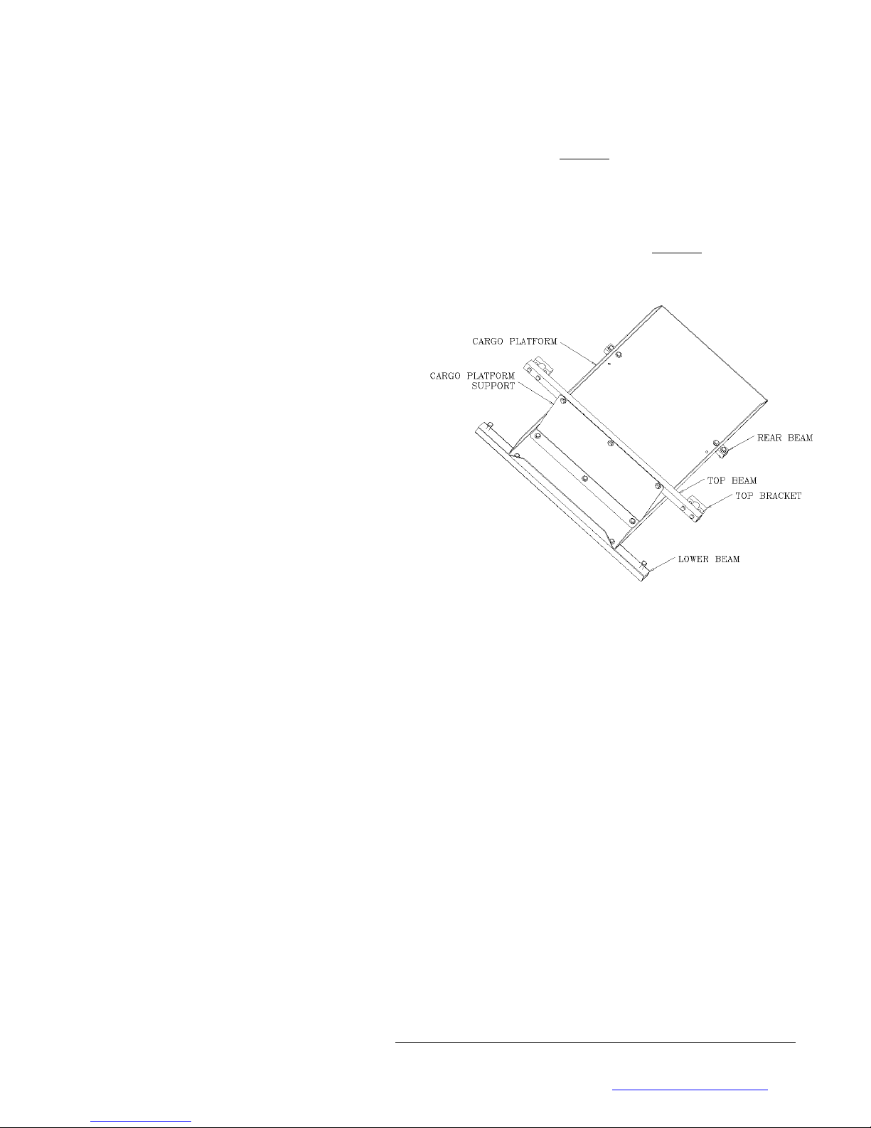
CARGO PLATFORM NSTALLAT ON
7) Find the cargo platform (18 x 30” aluminum
sheet). With the three langes up and the lange
down at the rear, slide the plat orm over the rear
beam orward to the lower beam. Install two ¼” x
2” bolts through the platform/lower beam at the
ront and two ¼” x 1¾” bolts through the
platform/rear beam. Rear beam should still be
loosely bolted. I all our bolts can not be installed, as
a last resort, you can ‘chase’ the hole with a ¼” drill.
8) Find the cargo platform support (8” x 18”
aluminum sheet). Place the support on the
platform, bent lange down, and attach with three
¼” x ¾” bolts. Tighten when all 3 bolts are in place.
9) Find the top beam (1” x 1” x 29 ½” square
aluminum tube). With the rubber pads to the rear,
(to go against the seat post) attach it to the support
with three ¼” x 1-½” bolts. Tighten bolts. (maybe
already assembled)
Figure 9
10) Find the two top brackets (3 ¼” x 1” ormed
aluminum). Place behind the seat tube and attach to
the top beam with two ¼” bolts.
Figure 10
Figure 6
www.blackbirdbikes.com

EZ-1 QUADRIBENT ASSEMBLY AND USER GUIDE
8
11) It is now time to tighten bolts in the ollowing
order:
Lower beam
Front beam
Rear Axle beam to angle brackets
Support to cargo platform (i not already tight)
Cargo platform to rear beam and lower beam
Top beam/support to top brackets at seat tube
STEER NG ASSEMBLY
12) Find steering levers and attach to handle bar
stem, as ar up as possible, with two 8mm x 45mm
machine screws & washers as shown in igure 12.
The labels on the steering lever should ace outboard
- right side o right bike and le t side o le t bike
(shown). The levers should be rotated about 15°
outboard in relation to the ront tire. Tighten both
8mm screws evenly, enough to hold in place.
Figure 12
13) Find steering tie rod assembly (should measure
28½” center to center) and attach to steering levers
using quick release pins, see igure 13.
Figure 13
14) Find and install parking brake on any o the our
brake levers as shown in igure 14. The parking
brake is intended to keep the Quadribent rom
rolling on relatively lat ground, when not in use.
Never park facing uphill or down hill.
Figure 14
www.blackbirdbikes.com

EZ-1 QUADRIBENT ASSEMBLY AND USER GUIDE
9
FRONT END WHEEL AL GNMENT
15) Check ront-end wheel alignment by measuring
the distance between the ront rims o the two bikes
as shown in igures 15, 16 & 17. Two measurements
are required. The irst is at axle height on the
leading edge o the ront rims. The second is at axle
height on the trailing edge o the ront rims. These
measurements should be approximately equal. A
di erence o up to a 1/16” is acceptable i the
leading edge measurement is smaller than the trailing
edge. This is commonly called “toe-in”.
Figure 15
Figure 16
Figure 17
18) I the two measurements show the ront wheels
are out o alignment, remove one end o the steering
tie rod and shorten or lengthen it as needed.
Shortening the steering tie rod will increase the “toe-
in” o the ront wheels.
Two wrenches are needed to release the lock or
“jam” nuts at the rod end bearing. (The rod end
bearings are both right hand thread so you can’t
adjust by turning the center rod like the turnbuckles).
A ter adjusting the steering tie rod length and
con irming the measurement, the lock or “jam” nuts
must be secured against the rod end bearings. I the
bearings bottom out (so you can’t shorten anymore)
turn back 3 turns each, loosen the steering levers and
rotate each one arther outboard.
A ter moving the steering levers, visually check that
they are about the same angle outboard, with the
two ront wheels straight. (rough adjustment).
Repeat steps 15 – 17 ( ine adjustment).
Wheel alignment should be checked regularly,
before/after a long ride, after riding on rough
roads.
19) Please check all nuts and bolts to ensure they are
astened properly.
When all hardware is tight and secure, mount the
seats to both bikes per the EZ-1 owner’s manual.
www.blackbirdbikes.com

EZ-1 QUADRIBENT ASSEMBLY AND USER GUIDE
10
Check proper operation o the brakes, ront and rear
shi ters a ter Quadribent is ully assembled. Test ride
to veri y adjustments.
DO NOT ALLOW ANYONE TO STAND OR
S T ON ANY OF THE QUADR BENT
CONNECT NG PARTS OR TO R DE
ANYWHERE EXCEPT ON THE SEAT.
20) The inal assembly step is the installation o the
seatbelts. Unclip or open the lower two seat back
mounting clips rom the EZ-1 koolback seat.
Thread the end o the seatbelt through the tri-glide
astener and then around the exposed seat rame as
shown in igure 20.
Figure 20
21) Insert the end o nylon strap back through the
tri-glide as shown in igure 21.
Figure 21
22) Insert the end o nylon strap back through the
tri-glide as shown in igure 22. Reconnect the middle
two seat back mounting buckles on the EZ-1 seat.
Repeat this process on both the right and le t side o
each seat on each bike.
Figure 22
23) Install the other end o the nylon straps through
the buckle as shown in igure 22. The buckle is
equipped with a quick release. Simply squeeze the
center o the buckle and it will open. Seat belt length
is adjustable by pulling on the ends o the nylon
straps. I the strap end becomes rayed it can be
sealed with a lame rom a candle.
Figure 23
www.blackbirdbikes.com

EZ-1 QUADRIBENT ASSEMBLY AND USER GUIDE
11
SPECIAL NEEDS CUSTOMIZATION
A second seat belt, at chest height, can be added to better secure “Special needs” kids and adults. Toe clips and
straps can be added to the pedals to secure eet to the pedals. Also extra straps can be added to the pedals to go
around the heel. Extra seats, seat belts, toe clips, straps and other accessories may be purchased rom your dealer
or Blackbird Sales. Call Blackbird Designs or the latest developments in accessories or people with “special
needs”.
Please include a copy o the Quadribent™ Assembly Instructions and User Guide with the storage box when
delivering the Quadribent™ to the customer.
QUADRIBENT DISASSEMBLY FOR SINGLE RIDING AND TRANSPORT
1. Lower kickstands on each bike or ind a second person to hold bike while completing this process.
2. Remove quick release pins rom steering tie rod and remove tie rod.
3. Remove bolts rom the le t hand bike at the ront beam, top beam/brackets, lower beam and rear axle
beam (both bolts).
4. Store bracket and all bolts, washers, nuts.
5. Care ully separate le t hand EZ-1. It can be ridden solo. The ront beam and cargo plat orm assembly can
be removed rom the right hand bike and ridden solo or transported. Store all loose pieces.
6. Reverse the list o procedures when reassembling your Quadribent or sociable tandem riding.
Caution – if lock nuts can be finger tightened all the way on, they need to be replaced. The Mark
4.0 Quadribent is not designed to be disassembled on a regular basis. Contact Blackbird Designs for
a Quick Release Kit.
____________________________________________________________________________________
QUADRIBENT REGISTRATION CARD
Please mail, email or ax this in ormation to Blackbird Sales so your in ormation you can be placed in our database
and alerted i necessary regarding service advisories and special o ers or upgrades that become available.
Name __________________________________________________________________________________
Address_________________________________________________________________________________
Phone___________________________________Email___________________________________________
Date Purchased_________________________Dealer Name________________________________________
Dealer Address____________________________________________Dealer Phone_____________________
Mail to: Blackbird Sales, 12721 Apple View Ln. Burnsville, MN 55337 Fax To: 952-929-5533
Email To: [email protected]
www.blackbirdbikes.com
Other manuals for EZ-1 Classic Quadribent
1
Table of contents
Other Blackbird Bicycle manuals


Popular Bicycle manuals by other brands

Betzold
Betzold 58825 instructions

Coast
Coast BUZZRAW RACE PLATES Assembly manual

ConsiderC
ConsiderC CVB-001 owner's manual

Air Creation
Air Creation RACER 447 Instruction and maintenance handbook

Green Bike Electric Motion
Green Bike Electric Motion City Premium 2020 instruction manual

Coboc
Coboc Merano manual


