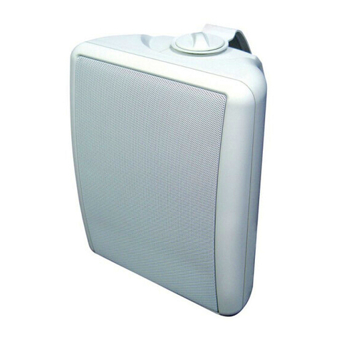
Blackboxav MESSAGE IN A SPEAKER User manual

mounted on drywall, the use of properly selected and installed wall-
anchors and screws is essential. Make sure that the screw head is at least
0.36 inches (approximately 3/8 inches) or larger in diameter so that it can
properly hold the backup cord eyelet (11).
g. Holding the speaker cabinet (7) with both hands, reinsert the ball
portion of the ball/shaft (3) into the wall bracket (4).
h. Hand tighten the molded nut (2) while positioning the speaker for the
intended orientation.
i. Once the orientation of the speaker is nalized, use the metal bar (5) in
one of the holes on the molded nut (2) and tighten securely.
j. Securely attach the other end (10) of the backup cord (8) to the MIAS, by
engaging it through the bar (12) on the back speaker.
k. Insert the programmed SD card label down into the SD card slot (14).
l. Connect the DC power cable to the power input point (13).
m. To adjust the volume, turn the volume control (15) clockwise to
increase the volume.
BRACKET ASSEMBLY AND MOUNTING
a. Loosen and remove the molded nut @ by turning it counter clockwise. Use
the 'supplied metal bar (2) if necessary by inserting it in one of the holes on the
molded nut (5).
b. Pull the ball/shaft (3) out of the wall bracket (4).
c. Slide on the molded nut (2) onto the ball/shaft (3) with threaded opening
facing the ball, and thread on the metal nut (1) all the way onto the ball/shaft
(3) with the nut (1)'s "knurled" surface facing away from the ball.
d. Screw on the ball/shaft (3) into the threaded insert on the back of the
speaker cabinet (6) until it is fully seated against the bottom of the insert.
e. Tighten the "knurled" nut (1) using a crescent wrench until it is rmly seated
against the back of the speaker and has fully locked the ball/shaft (3) and the
speaker cabinet together. Please note that once this nut is tightened, it may
embed some marks on the back of the speaker where the attachment is made.
However, these marks will be covered by the nut (1).
f. The back-up cord (8) provided as an additional measure to prevent the fall of
the speaker in case the speaker becomes detached from the wall bracket. One
of the two lower screws (9) that attach the wall bracket (4) to the wall, will need
to go through the eyelet (11) at the end of the cord before going through the
wall bracket hole. Mount the wall bracket (4) onto a wood stud on the wall,
using #10, minimum 1 inch long, pan head wood screws. Make sure that all 4
screws are driven into the stud and not in drywall. If the bracket needs to be
Safety note: Proper selection of mounting hardware not included herein and proper
assembly and installation of brackets, including but not limited to selection of
appropriate weight bearing support and bracket use with the specied speaker only is the
exclusive responsibility of the customer. Manufacturer disclaims any liability for the
selection of mounting hardware and or bracket installation.
MESSAGE IN A SPEAKER
AUDIO PRODUCT MANUAL

SPECIFICATIONS
Speaker
Driver Bass/midrange 100mm
Drivers Tweeter 12mm Titanium Laminate
Frequency Response 20Hz - 20kHz
Power Handling 200W - 50W
Sensitivity 89dB/2.83V/1m
Nominal Impedance 8 0hms
Dimensions (H x W x D) 228 x 155 x 139mm
Weight 2.7kg
Colour Silver
Messages
Message storage medium 1 * SD Flash Card
Maximum SD Card capacity 4.3Gbytes
Maximum number of messages 8
Message encoding format Windows PCM (*.wav)
Message sampling rate/type 22.05 KHz/16 bit mono
Maximum total message length >27 hours
Power on load time 30 seconds
Message Output
Playback sample rate/type 22.05 KHz/12 bit mono
Audio output 2W
Power Supply
External power supply 9 to 16V DC (12V nominal) / 1000mA
Power supply connector 1.3mm Inner=V+, Outer=0V
Operating Voltage 110 - 240V AC 50/60Hz Indoor Use Only
Connections
The power supply (9 – 16V DC, inner = +, outer = -) should be connected to the
PSU connector.
The programmed SD card should be inserted with label side down.
DO NOT connect an external amplier into the input located on the rear of the
speaker.
You may connect a second speaker to the input located on the rear of the
speaker. Not less than 8Ω.
PIR Detection Range
60° 30°
20°
2M
12 345
(M)
MESSAGE IN A SPEAKER
AUDIO PRODUCT MANUAL
Please read carefully and use in accordance with our safety instructions below:
1. Note; The adaptor may become warm during use or emit a slight
buzzing sound, this is quite normal.
2. Remove the adaptor from the mains supply before connecting the MIAS.
3. If you use a dierent power adaptor DO check polarity, or damage could
result to your MIAS. (Manufacturer takes no responsibility for damage caused if
using another power supply)
4. DO NOT attempt to open the adapter housing as there ar no serviceable parts
inside.
5. For indoor use only.
Notice: The socket-outlet shall be installed near the equipment and shall be
easily accessible.
PIR Operation
Programmable Delay from Power-Up 0 to 999 seconds
Programmable Delay between messages 0 to 999 seconds
FOR YOUR SAFETY

The audio le format for the MIAS is Windows PCM le format (i.e. .wav les).
The audio must be mono, 16 bit samples at 22.05 KHz sampling. The audio
should be normalized to 100% amplitude to ensure best audio quality when
played back on the MIAS. The SD card MUST be formatted as FAT with a blank
volume name before copying the 'wav' les. This is done by right clicking the
SD drive icon from 'My Computer' and selecting FORMAT.
The audio les on the PC hard disc MUST be named '01.wav', '02.wav' etc. up
to the last le to be copied. There should be no break in the le name
sequence i.e. the name of the last le should be equivalent to the total tracks
to be on the card. There can be a maximum of 8 audio les on the SD card.
You then copy each le in turn from the PC hard disc to the SD card root
directory. Do not put any other les on the SD card (except the ‘MODE.txt’ le
if required – see below).
Copying les to the SD card can take longer than the computer indicates i.e.
the computer will show that copying is nished but there is still data to be
transferred to the card. Please ensure all les have been copied to the SD
card before it is removed. The best way to conrm this is to ‘click’ the ‘Unplug
or Eject Hardware’ button in the ‘System Tray’ icons (bottom right of screen),
and then select ‘STOP xxxxxxxx’ where xxxxxxx represents the SD card drive.
If all the data has been transferred then a message will indicate that you can
remove the card, if not then wait a while and try stopping the device again.
Remember that you should not have‘My Computer’ or ‘Windows Explorer’
accessing the SD card at this time otherwise the computer will assume the
card is in use and will not allow it to be removed.
The programmed card should then be inserted into the MIAS with the label
side down.
By default, all messages are non-interruptible. This can be changed using an
additional ‘Mode’le on the SD card. See the section on ‘Operation with a
MODE le’below for further details.
PROGRAMMING THE SD CARD
The MODE le allows additional options to be programmed, which modify the way
the SBLite responds to the button inputs. This feature is available on SBLites with
rmware version SBLITE1.2 or later. By default, all the messages are non-
interruptible, i.e. once started the message cannot be interrupted by another
message button. However some (or all) messages can be assigned as interruptible
by programming a mode type for the particular message in a text le identied as
‘MODE.txt’. In addition some messages (and consequently button inputs)
can be assigned as randomly selectable. Additional features available with the
MODE le are programmable delays. One from power-on to checking the button
for the rst message; and also a delay between the end of a message and checking
the button to allow a new message to start. These delays are primarily intended to
allow operation with a PIR movement sensor.
The MODE le is a simple text le, which can be created using any simple text
editor on a PC. Alternatively blackbox-av can provide a‘Visual Basic’ programme,
which can assemble the MODE le using a simple ‘click-the-box’ user interface.
Each text line in the MODE le is a command, which sets either a time delay value
or a mode type for a particular message number. If a time delay is required then it
should be entered on the rst and/or second line of the MODE le. The line begins
with the letter ‘D’ followed by either‘X’or ‘Y’ followed by a 3-digit number.
DXzzz = Time from power-on to accepting the 1st button (zzz = seconds) N.B. all 3
digits must be entered e.g. DX030 is 30seconds delay from power-on.
DYzzz = Time from end of message to accepting the next button (zzz = seconds)
N.B. all 3 digits must be entered e.g. DY010 is 10seconds delay between messages.
The command for setting the message mode type begins with‘M’followed by a
number (1-8) representing the message, then ‘=’ then a letter identifying the mode
type for the message. The mode type letter are as follows:
N = Non interruptible
I = Interruptible
R = Random selection Non interruptible
r = random selection Interruptible
P = Play whilst the button is pressed.
OPERATION WITH A ‘MODE’ FILE
For audio encoding support please see:
http://www.blackboxav.co.uk/product-downloads/audio_encoding_guide.zip

E.g. M2=I means that message 2 can be interrupted.
If a message is identied as random then, whenever a random message
button is pressed, any of the messages set as random could be played.
The actual message played will be chosen at random from the list of all
random selections. Once a random message has been played, then it
will not be available for re selection until all random selections have been
played. The system will also ensure that there will not be a repeat of the
last message played when all selections become available again. The
‘R’ and ‘r’ cases allow for both interruptible and non-interruptible types of
random messages.
The ‘P’ mode type allows for a message to be played only while its
message button is pressed, i.e. if the button is released then the message
stops playing.
The ‘MODE.txt’ le should be copied to the SD card root directory similarly
to the audio les.
A typical complete MODE le could be as follows:
DX030
DY010
M1=N
M2=I
M3=R
M4=R
M5=R
M6=R
M7=R
M8=R
This has the following mode arrangement:
Time from power-up to checking the button input = 30seconds
Time from message end to checking the next button input = 10seconds
Message1 is Non-interruptible
Message2 is Interruptible
Message3 is random Non-interruptible
Message4 is random Non-interruptible
Message5 is random Non-interruptible
Message6 is random Non-interruptible
Message7 is random Non-interruptible
Message8 is random Non-interruptible
Using this mode le, the MIAS will wait 30seconds after power on before
checking the buttons. Then, if Button1 is pressed then message1 will play
and cannot be interrupted. At the end of the message, then the MIAS
will wait 10 seconds before checking the buttons again. This delay will
occur at the end of all messages that end normally, however should a
message be interrupted by a dierent message button then the MIAS will
play the new message immediately, without waiting the end-of-message
delay time.
MESSAGE IN A SPEAKER
AUDIO PRODUCT MANUAL
For a full list of FAQ’s visit our website
www.blackboxav.co.uk/message-in-a-speaker/
Table of contents
Other Blackboxav Speakers manuals
Popular Speakers manuals by other brands

Accessory Power
Accessory Power GO groove SonaVERSE BSE user guide
Infinity
Infinity ENTRA POINT FIVE HTS owner's guide
TrekStor
TrekStor Bluetooth MultiSpeaker 4in1 operating instructions
Philips
Philips HTL2193B quick start guide
Polaroid
Polaroid PLS92SP user manual

Home Art International
Home Art International WS-3201 instruction manual


