Blackrock Microsystems CerePlex Exilis User manual

Manufacturer
630 Komas Drive | Suite 200
Salt Lake City | UT 84108 | USA
P +1 801.582.5533 | F +1 801.582.1509
www.blackrockmicro.com
Revision 2.00 / LB-0889 –CerePlex Exilis: Instructions for Use –2019/05
© 2019 Blackrock Microsystems, LLC
CerePlex Exilis
Instructions for Use

Revision 2.00 / LB-0889 –CerePlex Exilis: Instructions for Use
© 2019 Blackrock Microsystems, LLC
2
Table of Contents
Warnings and Precautions............................................................4
Symbols ........................................................................................4
What This Manual Covers.............................................................5
Specifications................................................................................6
Overview of Hardware...................................................................7
Exilis Headstage .............................................................................7
Basic Functions ............................................................................7
CerePlex Exilis On/Off Switching..................................................8
CerePlex Exilis Battery and Charging...........................................8
Dimensions, Pinout and Labels...................................................10
Reference Selection ...................................................................11
Receiver and Antennas.................................................................12
Setting Up the CerePlex Exilis ....................................................14
Setting up the Antennas................................................................14
Assembling the Wireless System ..................................................15
Testing and Calibrating the Wireless System................................16
Wireless Data Transfer ...............................................................16
Maximum Sampling Frequency.....................................................16
Up-sampled Buffering Process ...................................................16
Automatic Wireless Data Validation...............................................17
Loss of Lock (LOL) .....................................................................17
Frame Check (FC)......................................................................17
Identical Stream Logic (ISL)........................................................17
Checksum...................................................................................18
Cleaning, Maintenance, and Disposal.........................................18
Troubleshooting ..........................................................................19

Revision 2.00 / LB-0889 –CerePlex Exilis: Instructions for Use
© 2019 Blackrock Microsystems, LLC
3
Warranty......................................................................................19
Return Merchandise Authorization (RMA) ..................................20
Support........................................................................................20
Manuals, Software Downloads, and Application Notes..................20
Complaints....................................................................................20
Issues or Questions.......................................................................20

Revision 2.00 / LB-0889 –CerePlex Exilis: Instructions for Use
© 2019 Blackrock Microsystems, LLC
4
Warnings and Precautions
•Do not touch any exposed metal plates or input contacts of the 36-pin Omnetics
connectors at the bottom of the CerePlex Exilis when in use. This may result in inducing
electric charge to the neural tissue. Irreversible damage may occur.
•Note that this product contains an internal battery. Please refer to the Cleaning,
Maintenance, and Disposal section for disposal instructions.
•Do not recharge the device with an uncertified charger, short circuit, crush, disassemble,
or heat above 100°C (212°F).
•When plugging in the CerePlex Exilis device to its mating connector, please ensure the
orientations of the connectors are matched, then carefully align the pins, and plugin
gently. Excessive force during connection and disconnection can damage the
connectors and cause harm to the subject.
•Use antistatic or ESD safe gloves when using the CerePlex Exilis or the wireless
receiver.
•The CerePlex Exilis device and its receiver system are only approved for use with
Blackrock Microsystems data acquisition systems.
•Do not use the CerePlex Exilis device with non-approved electrodes.
•The CerePlex Exilis must be used with a Blackrock Omnetics array, or a Blackrock
adaptor approved for use with alternative arrays.
•Use the CerePlex Exilis device in a clean and dry environment, do not use the CerePlex
Exilis device near liquids.
•Do not drop or put excessive force on the CerePlex Exilis device. High mechanic force
can damage the device permanently.
•Do not use the CerePlex Exilis with other RF radiator in the 3-4GHz frequency range,
which will cause interference to and from the CerePlex Exilis device.
•For cleaning the device, please use water and gauze to gently wipe the surface, do not
use isopropanol (IPA) for cleaning, since it will dissolve the acrylic clear surface coating
on the case.
Symbols
BS EN ISO 15223-1:2016 Medical Devices –Symbols to Be Used with Medical Device
Labels, Labeling, and Information to Be Supplied
Reference
Symbol
Title
Meaning
5.1.1
Manufacturer
Indicates the medical device
manufacturer.
5.1.3
Date of Manufacture
Indicates date of manufacture and
is accompanied by a date.
5.1.5
Batch Number
Indicates the manufacturer's batch
or lot code, for example on a
medical device or the
corresponding packaging. The

Revision 2.00 / LB-0889 –CerePlex Exilis: Instructions for Use
© 2019 Blackrock Microsystems, LLC
5
code shall be placed adjacent to
the symbol.
5.1.6
Catalog Number
Indicates the manufacturer’s
catalog number so that the device
may be identified. For Blackrock
Microsystems it is called the Part
Number (PN).
5.1.7
Serial Number
Indicates the manufacturer’s serial
number so that a specific medical
device can be identified.
5.4.3
Consult Instructions
for Use
Indicates the need for the user to
consult the instructions for use,
which you are currently reading.
5.4.4
Caution
Indicates the need for the user to
consult the instructions for use for
important cautionary information
such as warning and precautions
that cannot, for a variety of
reasons, be presented on the
medical device itself.
ISO 7000 / IEC 60417:2002 DB –Graphical Symbols for Use on Equipment
5134
Electrostatic
Sensitive Devices
Indicates packages containing
electrostatic sensitive devices, or to
identify a device or a connector
that has not been tested for
immunity to electrostatic discharge.
5140
Non-Ionizing
Electromagnetic
Radiation
Indicates equipment in the medical
electrical area that include RF
transmitters or that intentionally
apply RF electromagnetic energy
for diagnosis or treatment.
5639
Rechargeable
Battery
Indicates rechargeable cells or
batteries
What This Manual Covers
The Blackrock CerePlex Exilis is a fully digital wireless telemetry system for neural recording.
The Exilis is used in conjunction with a wireless receiver and either the Cerebus or CerePlex
Direct recording system for high fidelity transmission and recording of extracellular spikes and
local field potentials from the brain. The Blackrock CerePlex Exilis converts analog signals to
digital format proximal to the recording site, dramatically reducing noise introduced to the signal
during transmission. The Exilis can wirelessly transmit up to 96 channels of neural data sampled
at 30 kHz for up to 2.5 hours.

Revision 2.00 / LB-0889 –CerePlex Exilis: Instructions for Use
© 2019 Blackrock Microsystems, LLC
6
Specifications
Model Name
Blackrock CerePlex Exilis
Channel Count
32 (PN: 10631), 64 (PN: 10633),
or 96 (PN: 10451)
Input Frequency Range
0.3 Hz—7.5 kHz
Maximum Input Voltage
± 8.192mV with respect to reference
Resolution
16-bit ADC, 12-bit transmission to receiver
Input Impedance
1300 MΩ @ 10 Hz, 13 MΩ @ 1 kHz
Data Transmission
Wired and wireless
Battery Type
Li-ion rechargeable
Battery Capacity
3.7 V, 200 mAh
Device Run Time
Up to 2.5 Hours
Device Charge Time
1 Hour
Input Connector
Omnetics 36-pin connector A79027-001
Wireless Transmission Range
3 m line of sight, 1 m free roaming
Weight
9.87 g
Size
25 mm x 23 mm x 14 mm
Noise
<3 µV rms
Reference Selection
3 bank references + 1 custom reference + Ground
Water Ingress Protection
Ordinary Equipment, not fluid resistant, IP20

Revision 2.00 / LB-0889 –CerePlex Exilis: Instructions for Use
© 2019 Blackrock Microsystems, LLC
7
Overview of Hardware
The CerePlex Exilis system consists of two major subsystems: the headstage transmitter and
the wireless receiver. Each component is described in detail below. Accessories included with
the system are:
•(1) CerePlex Exilis (PN: 10631 (32Ch), 10633 (64Ch), 10451 (96Ch))
•(1) Populated HBA with Omnetics Connector (PN: 6176)
•(1) Wireless Receiver (PN: 9660)
•(8) Antennas
•(8) SMA antenna cables
•(8) SMA to N adaptors
•(1) 12 V AC-DC power supply
•(1) Micro-USB to USB A cable
•(1) 5-wire micro-USB to micro-USB cable
•(1) Magnetic wand
Exilis Headstage
Basic Functions
The CerePlex Exilis headstage combines a fully digital neural recording amplifier
with a radio-frequency transmitter. The amplifier is built on the same platform as
other Blackrock CerePlex recording headstages and offers equivalent low-noise
Figure 1 –Exilis overview.

Revision 2.00 / LB-0889 –CerePlex Exilis: Instructions for Use
© 2019 Blackrock Microsystems, LLC
8
performance. Data from the amplifier is encoded and transmitted to the receiving
antennas by an on-board radio and antenna. The battery and power-on indicator
LEDs, as well as the impedance mode switch and micro USB port are shown in
Figure 1.
CerePlex Exilis On/Off Switching
Power to the CerePlex Exilis headstage is provided by a rechargeable lithium-ion
battery housed within the headstage. A magnetic reed switch is used to power
cycle the device. To turn the power on or off, swipe the magnetic wand provided
with the system across the area shown in Figure 2.
CerePlex Exilis Battery and Charging
When the battery is low, the battery status LED will turn RED for about 5 minutes
before it is completely turned off. The battery can be recharged by connecting the
CerePlex Exilis headstage to the wireless receiver using the included 5-wire
micro-USB cable. The battery status LED will turn YELLOW while the headstage
is actively charging and will turn GREEN when charging is complete (Figure 3).
Use caution when removing the micro-USB cable as excessive force or twisting
can damage the connector on the headstage.
Figure 2 –Power cycling the Exilis.
Figure 3 –Battery status indicators.

Revision 2.00 / LB-0889 –CerePlex Exilis: Instructions for Use
© 2019 Blackrock Microsystems, LLC
9
The transmission frequency is set at the time of manufacture to 3.5 GHz. The
CerePlex wireless receiver must be tuned to the same frequency as the
transmitter. This process is described in Setting Up the CerePlex Exilis section
below. It is possible to use two complete CerePlex Exilis systems together for a
total of 192 channels if they are tuned to different frequencies. Contact a
Blackrock Microsystems representative if you are interested in using two
CerePlex Exilis systems simultaneously.
The Exilis device can be used in wired connection mode, the same 5-wire USB
cable for charging can be used to operate the CerePlex Exilis headstage in
“wired” mode. In wired mode, the headstage transmits data via the cable while it
charges through the receiver.
Revision 2.00 / LB-0889 –CerePlex Exilis: Instructions for Use
© 2019 Blackrock Microsystems, LLC
10
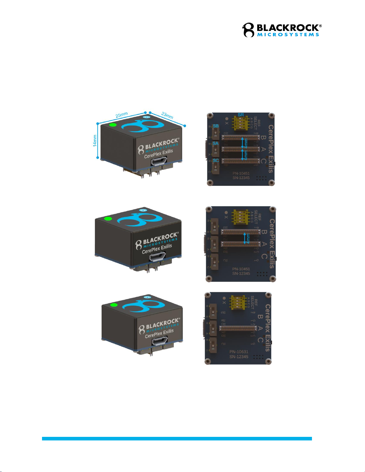
Dimensions, Pinout and Labels
The CerePlex Exilis wireless headstage measures 25mm×23mm×14mm (without
connectors). By default, the device has up to 3 Omnetics 36-pin Nano connectors
(A79027-001). The pitch (center to center) of the connectors is 4mm. The
pinouts, references labels, and bank labels of the 96-ch, 64-ch, and 32-ch Exilis
device are shown in Figure 4. The entire headstage weighs 9.87g including
battery and connectors.
Exilis 96Ch
Exilis 64Ch (Bank C connector is not installed)
Exilis 32Ch (Bank B and C connectors are not installed)
Figure 4 –Dimensions, pinouts, and labels.

Revision 2.00 / LB-0889 –CerePlex Exilis: Instructions for Use
© 2019 Blackrock Microsystems, LLC
11
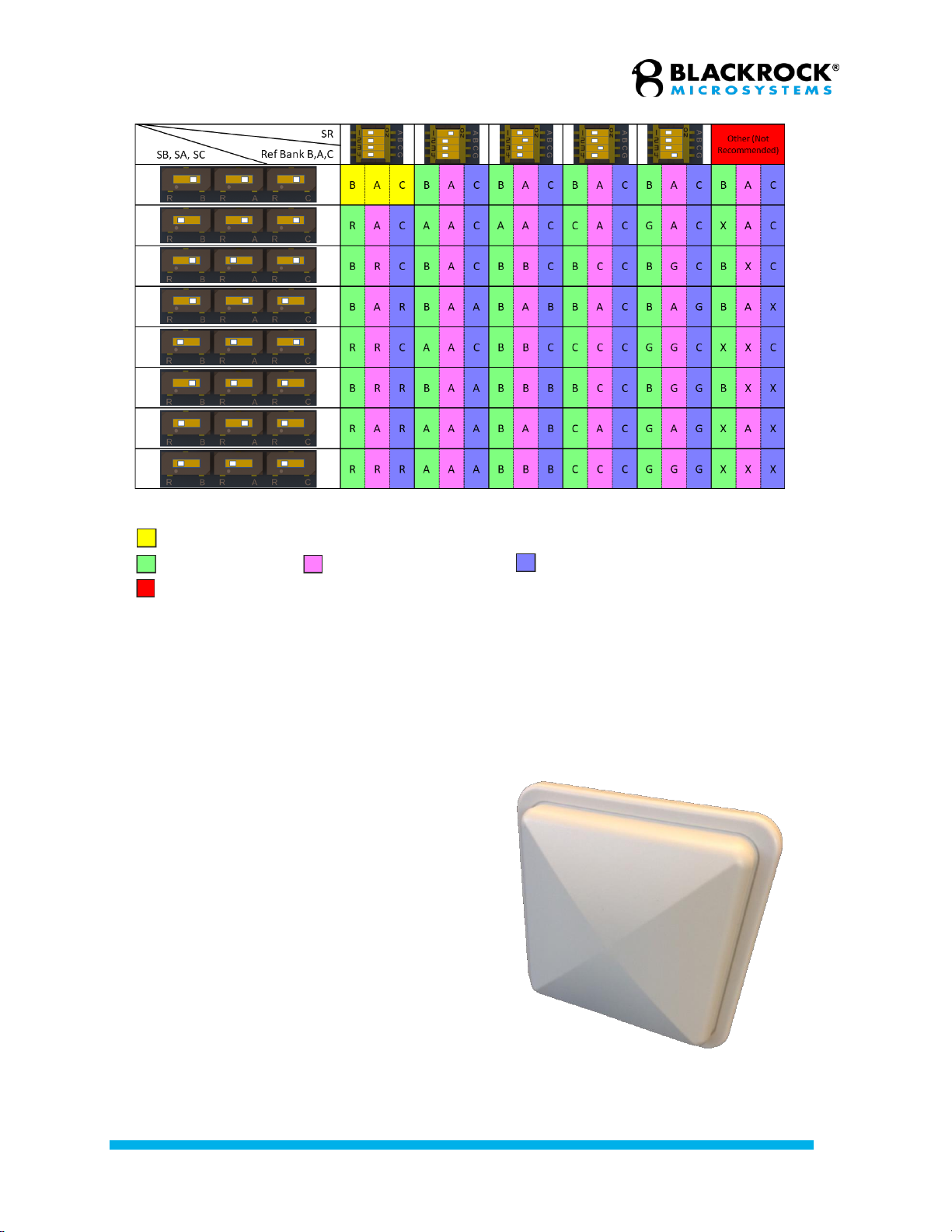
Reference Selection
CerePlex Exilis has a versatile reference selection feature that offers customers
great freedom on selecting the proper reference for their setup and achieving
optimal noise performance. There are two reference wires connected to the
Omnetics connector of each bank. These two wires are shorted on the device to
form a single reference, labeled as A, B, C (in Figure 5). There are three SPDT
switches (SA, SB, SC), one for each bank, to allow each bank to select its
reference from its Omnetics reference wire or a common reference R. There is
another 4-in-1 SPST switch (SR), which allows the user to connect the common
reference R to one of the following 4 references: A, B, C, and G (Ground). The
common reference R is connected to an exposed solder pads on the bottom of
the device. If needed, the user can solder a custom reference wire to the solder
pad with none of 4 references are selected in SR and use it as a custom
reference. The reference selection schematic and matrix are detailed in Figure 5
and Figure 6 below:
Figure 5 –Reference selection schematic.
Revision 2.00 / LB-0889 –CerePlex Exilis: Instructions for Use
© 2019 Blackrock Microsystems, LLC
12
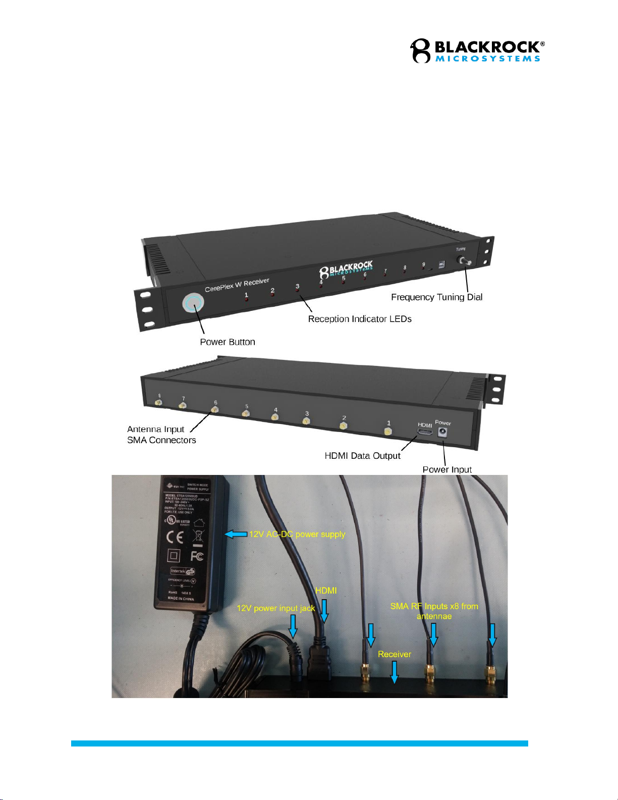
Receiver and Antennas
The CerePlex Exilis receiver can
use up to 8 antennas (Figure 7). to
acquire data from the CerePlex
Exilis headstage. The receiver
requires a robust signal from only
one antenna to reliably receive the
transmission. If signal strength
declines from one antenna, the
receiver will cycle through the
remaining antennas to find an
optimal signal. In this way, the 8
antennas can be used to cover a
larger operational area than would
be possible with a single antenna.
The receiver will display a blue
indicator LED on the front panel to
indicate an antenna receiving valid
data.
Figure 7 –Receiving antenna used with the CerePlex
Exilis system.
Figure 6 –Reference selection matrix.
“A”, “B”, “C”: Reference wires from Bank, A, B, C Omnetics connectors. “G”: Ground
reference. “R”: Custom reference.
Default Reference setting: Bank B, A, C have independent references: B, A, C.
Bank B reference Bank A reference Bank C reference
Not recommended switching positions for switch “SR”
“X”: Uncertain reference selection, depends on “SR” switching position and reference
impedance.
Revision 2.00 / LB-0889 –CerePlex Exilis: Instructions for Use
© 2019 Blackrock Microsystems, LLC
13
The antennas provided with the CerePlex Exilis system are rugged outdoor antennas
designed for harsh conditions. They have a wide beam width of over 50° to better cover
an experimental area. The antenna cables are low-loss coaxial cables specifically
designed for high performance at the frequency range used by the CerePlex Exilis
system.
After amplifying and decoding the wirelessly transmitted signal, the receiver relays the
data to either the digital hub—as part of a Cerebus system—or the CerePlex Direct for
further signal processing, display, and storage. Figure 8 shows the CerePlex Exilis
receiver with important features labeled.
Figure 8 –CerePlex Exilis Wireless Receiver and connections

Revision 2.00 / LB-0889 –CerePlex Exilis: Instructions for Use
© 2019 Blackrock Microsystems, LLC
14
Setting Up the CerePlex Exilis
This section describes how to connect the components of the CerePlex Exilis system to conduct
a recording session. The Blackrock digital neural signal simulator (DNSS) is used for a signal
source in this section, but the same procedure is used when recording from a subject.
Note: The DNSS is not included in the system and needs to be purchased separately.
Setting up the Antennas
1. Connect the SMA-N adapters to the antennas as shown in Figure 9.
2. Connect the SMA cables to the antennas and receiver.
3. Consider a 45-degree beam angle when assessing coverage of your entire experimental
area. The beams should overlap to provide the best recordings (Figure 10).
4. Consider that each antenna is phase-dependent. Use the orientation indicator arrows to
place antennas with different orientations as shown in Figure 11.
Figure 10 –Antenna beams and overlap.
Figure 11 –Optimal phase orientations of antenna
pairs.
5. The system will prioritize antennas in descending order from 8 to 1, so place antenna 8
to cover the most likely positions/orientation of the CerePlex Exilis.
6. Conductive materials disrupt the wireless signal and should not be placed between
antennas and the experimental area. Use plexiglass enclosures instead of metal cages,
if possible. If a metal cage must be used, place the antennas within the cage.
7. The CerePlex Exilis has a range of approximately 1 m. Every area of the cage should be
within 1 m of at least two antennas.
8. In setups where the CerePlex Exilis IS NOT expected to move throughout the entire
enclosure, placing two antennas near each other, pointed in the same direction, and
Figure 9 –Connecting the SMA adapter to the antenna.

Revision 2.00 / LB-0889 –CerePlex Exilis: Instructions for Use
© 2019 Blackrock Microsystems, LLC
15
oriented 90° from each other allows for reliable data recording (see Automatic Wireless
Data Validation, Page 17). See Figure 12 for a model antenna placement scheme for
this condition.
9. In setups where the CerePlex Exilis IS expected to move throughout the entire
enclosure, it is beneficial to ensure the entire enclosure gets maximum antenna
coverage. See Figure 13 for a model antenna placement scheme for this condition.
10. Every experimental setup is unique. Adjust your antenna orientation, location, and
distance while observing the blue antenna indicator lights on the receiver to achieve the
best placement for your setup.
11. For guidance on antenna placement, contact Blackrock Support at
support@blackrockmicro.com.
Assembling the Wireless System
1. Connect the 12 V power supply to the receiver.
2. Connect the HDMI-A cable to the receiver as well as the digital hub or CerePlex Direct.
3. Launch the Central Software Suite on the host PC.
4. Power on the components of the Blackrock data acquisition system—the digital hub and
NSP when using the Cerebus system, or the CerePlex Direct if using the CerePlex
Direct system. Refer to the associated data acquisition system product manuals as
needed.
5. Connect the CerePlex Exilis headstage to the pedestal connector on the Blackrock
DNSS as shown in Figure 14. Note: The DNSS is not included in the system and needs
to be purchased separately.
Figure 12 –Wireless antenna placement scheme for
animal with restricted movement.
Figure 13 –Wireless antenna placement scheme for
animal with unrestricted movement.

Revision 2.00 / LB-0889 –CerePlex Exilis: Instructions for Use
© 2019 Blackrock Microsystems, LLC
16
Testing and Calibrating the Wireless System
1. Place the CerePlex Exilis headstage and DNSS in the experimental area.
2. Turn on the CerePlex Exilis headstage using the magnetic wand as shown in Figure 2
above.
3. Turn on the CerePlex Exilis receiver by pressing the round power switch shown in
Figure 8 above.
4. The indicator LED on the digital hub or CerePlex Direct change from ORANGE to either
BLUE or GREEN, depending on the model, to indicate successful communication
between the CerePlex Exilis receiver and the data acquisition system.
5. If the receiver is properly tuned, the reception indicator LEDs on the CerePlex Exilis
receiver should illuminate. Adjust the frequency tuning dial to maximize the number of
antenna input channels with illuminated reception indicator LEDs.
6. If tuning the receiver frequency does not cause the reception indicator LEDs to
illuminate, it could be due to range issues. Ensure the antennas are pointed in the right
direction and oriented correctly (see Figure 10 and Figure 11) and that the CerePlex
Exilis is within 1 meter of the antenna(s) you are trying to tune.
Wireless Data Transfer
Maximum Sampling Frequency
The true sampling rate of the CerePlex Exilis is approximately 24.5 kS/s. For this reason,
recordings using the CerePlex Exilis system cannot record voltages at 30 kS/s even
when the sampling rate is chosen to be 30 kS/s through Central’s Hardware
Configuration tool. However, recordings from the CerePlex Exilis collected through
Central will still have data sampled at 30 kS/s. This is accomplished through an up-
sampled buffering process.
Up-sampled Buffering Process
The CerePlex Exilis transmits recordings from up to 96 channels in a single
frame. The receiver holds this frame’s information in an output buffer that is
sampled from the NSP at 30 kS/s, and the wireless receiver will clear its output
Figure 14 –The CerePlex Exilis on a DNSS.

Revision 2.00 / LB-0889 –CerePlex Exilis: Instructions for Use
© 2019 Blackrock Microsystems, LLC
17
buffer once it is sampled by the NSP. If the wireless receiver has not received a
new frame from the CerePlex Exilis before the NSP has sampled the receiver
again, the NSP will sample the same output buffer as its previous sample, and
the frame’s information will be duplicated in the recording. This results in
approximately 18% of the data points in CerePlex Exilis recordings to be
duplicates of their predecessors when that channel is configured to a 30 kS/s
sampling rate.
Automatic Wireless Data Validation
All firmware versions of the CerePlex Exilis and the wireless receiver have automatic
wireless data validation protocols, but these protocols differ depending on what firmware
is running on the CerePlex Exilis and the CerePlex receiver. Contact
support@blackrockmicro.com to check your firmware versions.
Loss of Lock (LOL)
The wireless data sent from the CerePlex Exilis is Manchester Encoded, which
contains rich clock frequency components in its spectrum for better facilitating
data recovery on the receiver side. Once the data is received by the receiver, the
receiver will try to recover the clock signal from the Manchester Encoded data
received by each antenna input. The ability to recover clock from the received
wireless data stream is a key requirement and indication of good signal reception
and ensures wireless communication quality and bit error rate. If the receiver can
recover clock signal from one antenna input, that antenna input channel’s
Reception Indicator LED will illuminate blue. Otherwise, that antenna input
channel’s Reception Indicator LED will not illuminate, indicating a poor signal
reception for that antenna, and the incoming data will be discarded. Antenna data
that passed the LOL check can then move to the next Frame Check process.
Frame Check (FC)
Data frames sent from the CerePlex Exilis begin with a 24-bit sync signal and
end with a 48-bit suffix. Once a sync signal is identified, the remaining bits are
read for the frame. An inability to read the sync and suffix messages de asserts
the “FrameCheck” flag and this specific frame of data is not buffered. In this
case, the previous valid frame of data is re-used. Frames passing the FC check
then go on to be further validated.
Identical Stream Logic (ISL)
When two or more antenna input channels pass the LOL check, the individual
channel’s data from a CerePlex Exilis frame get validated when more than one
antenna input channel is available. Each CerePlex Exilis channel is devoted 12
bits of information within a frame. The ISL compares information from two
wireless receiver antenna input channels, therefore making comparisons in 24-bit
segments. If two or more antenna input channels show identical information
between these 24-bit segments on different antenna input channels, the higher-
priority antenna input channel’s information for that 24-bit segment of the frame
goes into the wireless receiver’s output buffer. ISL occurs for all CerePlex Exilis
and receiver firmware versions.

Revision 2.00 / LB-0889 –CerePlex Exilis: Instructions for Use
© 2019 Blackrock Microsystems, LLC
18
Checksum
Unlike the ISL protocol, the checksum protocol requires only one antenna input
channel to operate. The last 12 bits of the CerePlex Exilis’s frame are the sum of
all previous 12-bit segments within that frame. Integer overflow is handled by
wrapping. If the checksum bits are not equal to the sum of the previous 12-bit
segments within the frame, that frame’s data is discarded and does not qualify to
enter the receiver’s output buffer. The checksum data validation step is only
utilized when the CerePlex Exilis firmware AND the receiver have v2.0 firmware
or later.
Cleaning, Maintenance, and Disposal
The rechargeable battery used to
power the CerePlex Exilis headstage is
rated for approximately 500 recharge
cycles. Eventually, the battery will lose
its ability to maintain its original
capacity. At such time, contact a
Blackrock representative if you would
like to purchase a replacement.
The CerePlex Exilis headstage should
be kept dry and free of debris. A gentle
cleaning using small amounts of water
with gauze can clean the outside of the
headstage if necessary.
CerePlex Exilis headstage allows up to
3 (depends on channel number
configurations) 36-pin Omnetics
A79027-001 connectors that permit
connection between
microelectrodes/connector assembly on
the subject and the CerePlex Exilis
headstage (Figure 15). Connect and disconnect with care to prevent bending and breaking the
delicate pins of the connectors.
All devices, both used and unused, should not be disposed with household waste. Return to a
recycling point for electric and electronic devices.
Figure 15 –36-pin Omnetics A79027-001 connectors

Revision 2.00 / LB-0889 –CerePlex Exilis: Instructions for Use
© 2019 Blackrock Microsystems, LLC
19
Troubleshooting
Some common error states and their respective resolutions are listed below. For further
information please contact Blackrock Support at support@blackrockmicro.com.
Problem
Symptom
Failure
Potential fix
CerePlex Exilis
does not turn on
using the
magnetic wand.
There is no signal
on Central Spike
Panel and no Blue
LEDs on receiver.
This may be
caused by a
depleted
battery.
Please recharge the CerePlex
Exilis device use the Micro-USB
cable through the computer USB
port or through the receiver.
Signal frequently
cuts out or is
very noisy.
The blue LEDs on
the receiver are
blinking frequently.
This is likely
due poor
wireless link
quality.
Retune your receiver following the
instructions in the Testing and
Calibrating the Wireless System
section above.
The antennas need to be properly
mounted to provide maximum
coverage to achieve best signal
quality. See Setting Up the
CerePlex Exilis (Page 14).
High baseline
noise, i.e. low
signal-to-noise
ratio (SNR)
Central Single
Neural Channel
shows no spikes
and jagged
waveforms.
Blue connection
LED on CerePlex
Exilis is off or
blinking.
Poor electrical
connections
and grounding.
Test alternative reference
selections.
Ground sources of electrical noise
near the experimental area to earth
ground. DO NOT ground the
animal to earth ground.
Verify that the CerePlex Exilis is
plugged in correctly.
Warranty
Blackrock Microsystems (“Blackrock”) warrants its products are free from defects in materials
and manufacturing for a period of one year from the date of shipment. At its option, Blackrock
will repair or replace any product that does not comply with this warranty. This warranty is
voided by: (1) any modification or attempted modification to the product done by anyone other
than an authorized Blackrock employee; (2) any abuse, negligent handling or misapplication of
the product; or (3) any sale or other transfer of the product by the original purchaser.
Except for the warranty set forth in the preceding paragraph, Blackrock provides no warranties
of any kind, either express or implied, by fact or law, and hereby disclaims all other warranties,
including without limitation the implied warranties of merchantability, fitness for a particular
purpose, and non-infringement of third-party patent or other intellectual property rights.
Blackrock shall not be liable for special, indirect, incidental, punitive, exemplary or consequential
damages (including without limitation, damages resulting from loss of use, loss of profits,
interruption or loss of business or other economic loss) arising out of non-compliance with any

Revision 2.00 / LB-0889 –CerePlex Exilis: Instructions for Use
© 2019 Blackrock Microsystems, LLC
20
warranty. Blackrock’s entire liability shall be limited to providing the remedy set forth in the
previous paragraph.
Return Merchandise Authorization
(RMA)
In the unlikely event that your CerePlex Exilis needs to be returned to Blackrock for repair or
maintenance, do not send any equipment back without a Return Merchandise Authorization
Number. An RMA number will be issued to you by a Blackrock representative. If you need to
obtain an RMA number, you may contact a product support representative at +1 (801) 582 5533
or by emailing support@blackrockmicro.com.
Once an RMA number has been issued, it is important to safely pack the returned item for
shipping back to Blackrock. It is preferred that you save the original boxes and packing
materials that your system arrived in for return shipment. Please address the package as
follows:
Blackrock Microsystems, LLC
ATTN: RMA#
630 S. Komas Dr., Suite 200
Salt Lake City, UT 84108 USA
Tel: +1 (801) 582 5533
Support
Blackrock prides itself in its customer support. For additional information on this product or any
of our products, you can contact our Support team through the contact information below:
Manuals, Software Downloads, and Application
Notes
www.blackrockmicro.com/technical-support
Complaints
When filing a complaint, please provide the product description, product number,
software version, lot number, complainant's name and address, and the nature of the
complaint.
Issues or Questions
www.blackrockmicro.com/technical-support
support@blackrockmicro.com
U.S. +1 (801) 839 1062
The CerePlex Exilis is not for use on human subjects.
Table of contents
Popular Transmitter manuals by other brands


Becker
Becker Centronic TimeControl TC4410-II Assembly and operating instructions

Zaxcom
Zaxcom ZMT-421 user manual

CET
CET ART Operation manual

Kobold
Kobold PAD operating instructions

Lectrosonics
Lectrosonics T6 operating instructions

PCB Piezotronics
PCB Piezotronics 682A06 Installation and operating manual

Silent Alert
Silent Alert MM4A-2212-EU quick start guide

Smart-Fly
Smart-Fly Ignition Cutoff user guide

Transmitter Solutions
Transmitter Solutions Stinger2 310LID22V manual
GENLED
GENLED Acolyte DiGidot CTRLPIXELTRMR manual

Vaisala
Vaisala HUMICAP HMD70U operating manual

Invonics
Invonics EchoStream EN1233S installation instructions