Blancett B3000 User manual

Digital Flow Monitor
B3000
DSY-PM-00022-EN-14 (April 2018) User Manual
C
L
A
S
S
I
F
I
E
D

Digital Flow Monitor, B3000
Page ii April 2018DSY-PM-00022-EN-14

CONTENTS
Scope of This Manual � � � � � � � � � � � � � � � � � � � � � � � � � � � � � � � � � � � � � � � � � � � � � 5
Unpacking and Inspection � � � � � � � � � � � � � � � � � � � � � � � � � � � � � � � � � � � � � � � � � 5
Safety � � � � � � � � � � � � � � � � � � � � � � � � � � � � � � � � � � � � � � � � � � � � � � � � � � � � � � � 5
Terminology and Symbols� � � � � � � � � � � � � � � � � � � � � � � � � � � � � � � � � � � � � � � 5
Considerations � � � � � � � � � � � � � � � � � � � � � � � � � � � � � � � � � � � � � � � � � � � � � � 5
Electrical Symbols � � � � � � � � � � � � � � � � � � � � � � � � � � � � � � � � � � � � � � � � � � � � 6
Introduction� � � � � � � � � � � � � � � � � � � � � � � � � � � � � � � � � � � � � � � � � � � � � � � � � � � 6
Installation� � � � � � � � � � � � � � � � � � � � � � � � � � � � � � � � � � � � � � � � � � � � � � � � � � � � 7
Connecting the B3000 to a Frequency Output Device � � � � � � � � � � � � � � � � � � � � � 7
Power Connections � � � � � � � � � � � � � � � � � � � � � � � � � � � � � � � � � � � � � � � � � � � � � � 9
Standard� � � � � � � � � � � � � � � � � � � � � � � � � � � � � � � � � � � � � � � � � � � � � � � � � � 9
Solar � � � � � � � � � � � � � � � � � � � � � � � � � � � � � � � � � � � � � � � � � � � � � � � � � � � 10
Operating the Monitor � � � � � � � � � � � � � � � � � � � � � � � � � � � � � � � � � � � � � � � � � � � 11
Programming Mode � � � � � � � � � � � � � � � � � � � � � � � � � � � � � � � � � � � � � � � � � 11
Programming Using Frequency Output Turbine Flow Meters � � � � � � � � � � � � � � � 12
Menu Structure� � � � � � � � � � � � � � � � � � � � � � � � � � � � � � � � � � � � � � � � � � � � � � � � 14
Liquid� � � � � � � � � � � � � � � � � � � � � � � � � � � � � � � � � � � � � � � � � � � � � � � � � � � 14
Advanced I/O Liquid � � � � � � � � � � � � � � � � � � � � � � � � � � � � � � � � � � � � � � � � � 16
Gas � � � � � � � � � � � � � � � � � � � � � � � � � � � � � � � � � � � � � � � � � � � � � � � � � � � � 18
Advanced I/O Gas � � � � � � � � � � � � � � � � � � � � � � � � � � � � � � � � � � � � � � � � � � � 20
Liquid (Solar Powered) � � � � � � � � � � � � � � � � � � � � � � � � � � � � � � � � � � � � � � � � 22
Gas (Solar Powered)� � � � � � � � � � � � � � � � � � � � � � � � � � � � � � � � � � � � � � � � � � 24
Programming � � � � � � � � � � � � � � � � � � � � � � � � � � � � � � � � � � � � � � � � � � � � � � � � � 26
Liquid� � � � � � � � � � � � � � � � � � � � � � � � � � � � � � � � � � � � � � � � � � � � � � � � � � � 26
Gas � � � � � � � � � � � � � � � � � � � � � � � � � � � � � � � � � � � � � � � � � � � � � � � � � � � � 39
Return to Run Mode � � � � � � � � � � � � � � � � � � � � � � � � � � � � � � � � � � � � � � � � � 39
Troubleshooting Guide� � � � � � � � � � � � � � � � � � � � � � � � � � � � � � � � � � � � � � � � � � � 40
Default K-Factor Values � � � � � � � � � � � � � � � � � � � � � � � � � � � � � � � � � � � � � � � � � � � 40
User Manual
Page iii
April 2018 DSY-PM-00022-EN-14

Battery Replacement (B30A/B/X/Z only) � � � � � � � � � � � � � � � � � � � � � � � � � � � � � � � � 41
NEMA 4X Enclosure � � � � � � � � � � � � � � � � � � � � � � � � � � � � � � � � � � � � � � � � � � 41
Explosion-Proof Enclosure� � � � � � � � � � � � � � � � � � � � � � � � � � � � � � � � � � � � � � 42
K-Factors Explained � � � � � � � � � � � � � � � � � � � � � � � � � � � � � � � � � � � � � � � � � � � � � 43
Calculating K-factors � � � � � � � � � � � � � � � � � � � � � � � � � � � � � � � � � � � � � � � � � 43
Declaration of Conformity � � � � � � � � � � � � � � � � � � � � � � � � � � � � � � � � � � � � � � � � � 45
Explosion-Proof Enclosure� � � � � � � � � � � � � � � � � � � � � � � � � � � � � � � � � � � � � � � � � 46
Installation � � � � � � � � � � � � � � � � � � � � � � � � � � � � � � � � � � � � � � � � � � � � � � � 46
Modbus Interface � � � � � � � � � � � � � � � � � � � � � � � � � � � � � � � � � � � � � � � � � � � � � � 49
Modbus Register / Word Ordering� � � � � � � � � � � � � � � � � � � � � � � � � � � � � � � � � 50
Specications� � � � � � � � � � � � � � � � � � � � � � � � � � � � � � � � � � � � � � � � � � � � � � � � � 52
Part Number Construction� � � � � � � � � � � � � � � � � � � � � � � � � � � � � � � � � � � � � � � � � 54
Blancett B3000 Display� � � � � � � � � � � � � � � � � � � � � � � � � � � � � � � � � � � � � � � � 54
Blancett B3000 Explosion-proof Display � � � � � � � � � � � � � � � � � � � � � � � � � � � � � 54
Dimensions � � � � � � � � � � � � � � � � � � � � � � � � � � � � � � � � � � � � � � � � � � � � � � � � � � 55
Meter Mount � � � � � � � � � � � � � � � � � � � � � � � � � � � � � � � � � � � � � � � � � � � � � � 55
Remote Mount � � � � � � � � � � � � � � � � � � � � � � � � � � � � � � � � � � � � � � � � � � � � � 55
Explosion-proof � � � � � � � � � � � � � � � � � � � � � � � � � � � � � � � � � � � � � � � � � � � � 55
Swivel Mount� � � � � � � � � � � � � � � � � � � � � � � � � � � � � � � � � � � � � � � � � � � � � � 56
Digital Flow Monitor, B3000
Page iv April 2018DSY-PM-00022-EN-14

Scope of This Manual
Page 5April 2018 DSY-PM-00022-EN-14
SCOPE OF THIS MANUAL
This manual is intended to help you get the B3000 flow monitor up and running quickly�
MPORTANTI
Read this manual carefully before attempting any installation or operation. Keep the manual
accessible for future reference.
UNPACKING AND INSPECTION
Upon opening the shipping container, visually inspect the product and applicable
accessories for any physical damage such as scratches, loose or broken parts, or any other
sign of damage that may have occurred during shipment�
OTE:NIf damage is found, request an inspection by the carrier’s agent within 48 hours of
delivery and file a claim with the carrier� A claim for equipment damage in transit
is the sole responsibility of the purchaser�
SAFETY
Terminology and Symbols
Indicates a hazardous situation, which, if not avoided, is estimated
to be capable of causing death or serious personal injury�
Indicates a hazardous situation, which, if not avoided, could result in
severe personal injury or death�
Indicates a hazardous situation, which, if not avoided, is estimated
to be capable of causing minor or moderate personal injury or
damage to property�
Considerations
The installation of the B3000 flow monitor must comply with all applicable federal, state,
and local rules, regulations, and codes�
EXPLOSION HAZARD SUBSTITUTION OF COMPONENTS MAY IMPAIR SUITABILITY FOR
CLASS I, DIVISION 2.
AVERTISSMENT
RISQUE D’EXPLOSION LA SUBSTITUTION DE COMPOSANTS PEUT RENDRE
CEMATÉRIEL INACCCEPTABLE POUR LES EMPLACEMENTS DE CLASSE I, DIVISION 2.
DO NOT CONNECT OR DISCONNECT EITHER POWER OR OUTPUTS UNLESS THE AREA IS
KNOWN TO BE NONHAZARDOUS.
AVERTISSMENT
RISQUE D’EXPLOSION. NE PAS DÉBRANCHER TANT QUE LE CIRCUIT EST SOUSTENSION,
À MOINS QU’LL NE S’AGISSE D’UN EMPLACEMENT NON DANGEREUX.
Introduction
Page 6 April 2018DSY-PM-00022-EN-14
MPORTANTI
Not following instructions properly may impair safety of equipment and/or personnel.
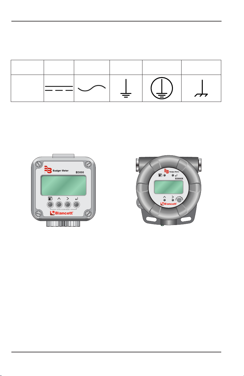
Electrical Symbols
Function Direct
Current Alternating
Current Earth
(Ground) Protective
Ground Chassis
Ground
Symbol
INTRODUCTION
The B3000 flow monitor incorporates state-of-the-art, digital signal processing technology,
designed to provide exceptional flexibility at a very affordable price� Though designed
for use with Blancett flow sensors, this monitor can be used with almost any flow sensor
producing a low amplitude AC output or contact closure signal�
Figure 1: B3000 Flow monitor (NEMA 4X) Figure 2: B3000 Flow monitor (Ex-Proof)
This monitor can accept low-level frequency input signals typically found in turbine flow
sensors� The output signal for these types of sensors is a frequency proportional to the rate
of flow� The B3000 monitor uses the frequency information to calculate flow rate and total
flow� Through the use of the programming buttons, you can select rate units, total units and
unit time intervals among other functions� If required, the monitor can easily be
re-configured in the field� Finally, you can choose between simultaneously showing rate
and total, or alternating between rate and grand total�
The monitor is available in two different levels of functionality and two packaging options�
The base model provides all the functions necessary for the most common flow metering
applications� The advanced version adds communications capabilities over an RS485 bus
using Modbus RTU and control outputs� The B3000 monitor can be powered using loop,
battery or solar power�
Packaging options include a polycarbonate, NEMA 4X version and an aluminum explosion
proof enclosure�

Installation
Page 7April 2018 DSY-PM-00022-EN-14
INSTALLATION
Connecting the B3000 to a Frequency Output Device
Most turbine flow sensors produce a frequency output that is directly proportional to the
volumetric flow through the sensor� There are, however, different output waveforms that
can be presented to the display device depending on the transducer that converts the
mechanical motion of the turbine into an electrical signal�
The B3000 monitor has two jumpers for setting the type of signal and the minimum
amplitude of the signal that it accepts� First, establish the type of output provided by the
flow sensor� The outputs almost always fall into one of two types�
• Type 1 is the unaltered frequency signal coming from an un-amplified magnetic
pickup� This signal is normally a sine wave in appearance, and the amplitude of the
waveform varies with the flow� Small turbines have comparatively small rotating
masses so they produce a smaller amplitude waveform and higher frequencies than
larger turbine sensors�
• Type 2 is the frequency signal from the transducer is amplified, wave shaped or both,
to produce a waveform of a specified type and amplitude� Most amplified transducers
output a square wave shape at one of many standard amplitudes� For example a
popular amplified output is a 10V DC square wave�
If the flow sensors output signal is type 1, you must also determine the minimum
amplitude of the frequency output� The B3000 monitor has a high or low signal sensitivity
setting� Use the high signal sensitivity (30 mV) with low amplitude (usually small) turbine
flow sensors� Use the low signal sensitivity setting (60 mV) for larger turbines and amplified
transducers (see Figure 3 and Figure 4)�
OTE:NUse the high signal sensitivity setting where the minimum signal amplitude is
below 60 mV� Setting the sensitivity lower than necessary may allow of noise
interference�
JP1
JP2
JP3
Input Total Pulse Signal
TB1
Mag
Pulse
Iso
OC
Low
High
Input Waveform Selection
(Magnetic Pickup Selection Shown)
Input Signal Level Selection
(Low Signal Sensitivity (60 mV) Selection Shown) Freq. In
+
–
Gnd
JP1
Input
MagPulse
JP2
TB2
TB1
P1
Signal
LowHigh
P1
Input Waveform Selection
(Magnetic Pickup Selection Shown)
Input Signal Level Selection
(Low Signal Sensitivity (60 mV) Selection Shown)
Figure 3: Input jumper settings (NEMA 4X) Figure 4: Input jumper settings (Ex-Proof)
When the type of waveform and input signal level (amplitude) are determined, set the
jumpers on the B3000 monitor circuit board�

Installation
Page 8 April 2018DSY-PM-00022-EN-14
For typical variable reluctance magnetic pickups, set the waveform selection jumper
for Mag� Determine the setting for the input level by looking at the magnetic pickup
specifications� If the minimum amplitude at the minimum rated flow is greater than 60 mV,
use the low signal sensitivity jumper position (see Figure 3 on page 7 and Figure 4 on
page 7)�
If the minimum signal level is below 60 mV, use the high signal sensitivity jumper position�
JP1
JP2
JP3
Input Total Pulse Signal
P1
Freq.In
4-20mA
IsoTotal Pluse
TR_B
TR_A
RS485Gnd
Setpoint 1
Setpoint 2
Gnd
+
–
+
–
+
–
TotalReset
OCTotal Pluse
SignalGnd
TB1
Mag
Pulse
Iso
OC
Low
High
Mag
Pulse
JP1
Input
Freq.I n
4-20mA
IsoTotal Pluse
+
–
+
–
+
–
TotalReset
OCTotal Pluse
Signal Gnd
TR_B
TR_A
RS485 Gnd
Setpoint 1
Setpoint 2
Gnd
+
–
P2 3.6Vdc
Battery
JP3
TotalPulse
ISO OC
JP1
Input
MagPulse
JP2
TB2
TB1
P1
Signal
LowH igh
P1
JP1
Input
MagPulse
Figure 5: Typical magnetic pickup connection
(NEMA 4X)
Figure 6: Typical magnetic pickup connection
(Ex-Proof)
For amplified input signals the input jumper should be set to Pulse and the signal jumper
set to Low (see Figure 7 and Figure 8)�
OTE:NAmplified magnetic pickups require an external power source� The B3000 does
not supply power to an amplified pickup�
JP1
JP2
JP3
Input Total Pulse Signal
P1
Freq.In
4-20mA
IsoTotal Pluse
TR_B
TR_A
RS485Gnd
Setpoint1
Setpoint2
Gnd
+
–
+
–
+
–
TotalReset
OCTotal Pluse
SignalGnd
TB1
Mag
Pulse
Iso
OC
Low
High
POWER
SUPPLY
Mag
Pulse
JP1
Input
Freq.In
4-20mA
IsoTotal Pluse
+
–
+
–
+
–
TotalReset
OCTotal Pluse
Signal Gnd
TR_B
TR_A
RS485 Gnd
Setpoint 1
Setpoint 2
Gnd
+
–
P2 3.6Vdc
Battery
JP3
TotalPulse
ISO OC
JP1
Input
MagPulse
JP2
TB2
TB1
P1
Signal
LowHigh
P1
POWER
SUPPLY
JP1
Input
MagPulse
Figure 7: Typical amplified pickup connection
(NEMA 4X)
Figure 8: Typical amplified pickup connection
(Ex-Proof)
Power Connections
Page 9April 2018 DSY-PM-00022-EN-14
POWER CONNECTIONS
Standard
The power supply used in the B30A/B/X/Z is an internal lithium 3�6V DC D cell that will
power the monitor for about six years when no outputs are used� The monitor can also
get power from a 4…20 mA current loop (see Figure 9 and Figure 10)� If the current loop
is used a sensing circuit within the monitor detects the presence of the current loop and
disconnects the battery from the circuit� The B30S uses solar power only�
JP1
JP2
JP3
Input Total Pulse Signal
P1
Freq. In
4-20mA
Iso Total Pluse
TR_B
TR_A
RS485 Gnd
Setpoint 1
Setpoint 2
Gnd
+
–
+
–
+
–
Total Reset
OC Total Pluse
Signal Gnd
TB1
Mag
Pulse
Iso
OC
Low
High
4…20 mA
Current Loop
(10…28V DC)
Load
10…28V DC
Freq. In
4-20mA
Iso Total Pluse
+
–
+
–
+
–
Total Reset
OC Total Pluse
Signal Gnd
TR_B
TR_A
RS485 Gnd
Setpoint 1
Setpoint 2
Gnd
+
–
P2 3.6Vdc
Battery
JP3
Total Pulse
ISO OC
JP1
Input
MagPulse
JP2
TB2
TB1
P1
Signal
LowHigh
P1
4…20 mA
Current Loop
(10…28V DC)
Load
10…28V DC
Figure 9: Loop power connections (NEMA 4X) Figure 10: Loop power connections (Ex-Proof)
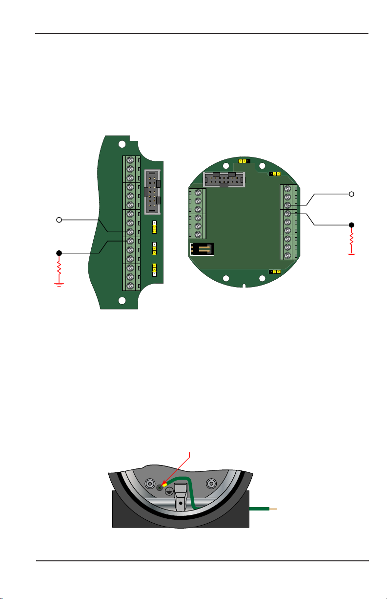
GROUNDING FOR THE EXPLOSION PROOF ENCLOSURE IS NECESSARY. THE EXPLOSION
PROOF ENCLOSURE IS PROVIDED WITH A GROUNDING SCREW ON THE INSIDE OF THE
ENCLOSURE. THE CONDUCTOR USED FOR GROUNDING MUST BE OF A WIRE GAGE
EQUAL TO OR GREATER THAN THE SIGNAL WIRES BEING USED. SEE FIGURE 11.
The explosion proof enclosure is provided with a grounding screw on the inside of the
enclosure� The conductor used for grounding must be of a wire gage equal to or greater
than the signal wires being used�
To Earth Ground
Grounding Screw
Figure 11: Required grounding for Ex-proof enclosure

Power Connections
Page 10 April 2018DSY-PM-00022-EN-14
Solar
A solar cell mounted on the top of the monitor in the B30S charges an internal 3�6V DC
nickel-cadmium battery that powers the monitor� A fully charged battery powers the
monitor for approximately 30 days� The solar powered B3000 has a single totalizing pulse
output and cannot be powered by a 4…20 mA loop�
Solar Cell
Figure 12: Solar powered B3000
Operating the Monitor
Page 11April 2018 DSY-PM-00022-EN-14
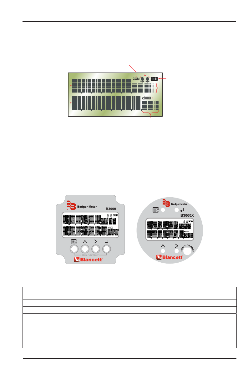
OPERATING THE MONITOR
The monitor has three modes of operation referred to as the Run, Programming, and
Extended Programming modes�
2
1Battery
Indicator
Alarm
Activation
Rate
Units
Totalizer
Units
Totalizer
Multiplier
Total
Rate
Communications
Indicator
Figure 13: Display annunciators
To access the Programming mode, momentarily press and then release MENU until the first
programming screen displays� The Extended Programming mode is entered by pressing and
holding MENU until the first programming option appears� After programming the display
with the necessary information, a lock out feature is available to prevent unauthorized
access or changing of the meter’s setup parameters�
Programming Mode
COM 12
COM 12
Figure 14: Keypad detail
Buttons
MENU Switches to Program mode, press and hold for three seconds to enter Extended
Programming mode, and is used in reset process
UP Scrolls forward through the parameter options and increments numeric variables
RIGHT Scrolls backward through the parameter options and moves the active digit to the right
ENTER Saves programming information, advances to the next programming parameter, and is
used in the reset process
TOTAL
FLOW
RESET
Explosion-proof only—allows the total to be reset without opening up the case
NOTE: The functionality can be enabled or disabled through the Extended Programming
menu item RST Key� The factory default is Disabled�

Operating the Monitor
Page 12 April 2018DSY-PM-00022-EN-14
Special Functions
MENU + ENTER – Simultaneously press and hold to reset the current totalizer�
MENU - Press and hold menu for three seconds to enter extended programming
mode�
UP + Right – Simultaneously press and hold to show the firmware version
number, then the grand total�
UP – In run mode increases display contrast�
RIGHT – In run mode decreases display contrast�
Explosion-Proof Models Only
Explosion-proof models are equipped with a through-the-glass total reset function� This
function allows the user to reset the monitor without removing the front cover� To
enable this function, see “Enable Reset Through the Glass (Explosion-Proof Models Only)” on
page32�
To use this function, press and hold your finger to the glass of the monitor over the area
marked Total Flow Reset for two seconds� When the monitor recognizes your finger is on
the glass, the outline of the battery icon in the upper right corner of the screen disappears�
When the monitor displays Press to Reset, remove your finger from the glass for one second,
then place it back on the same area of glass for two seconds� The monitor flashes Tot Rst�
The monitor displays 0 for the totals when the operation is complete� The timing of placing
and removing your finger from the glass is an important part of this process� If the reset
does not work the first time, try the operation again making sure that the timing is correct�
Modes
RUN – Normal operating mode�
PROGRAM – Used to program variables into the display�
EXTENDED PROGRAM –Used to program advanced variables into the display�
TEST –Used as a diagnostic tool to show input frequency and totalizer counts�
Programming Using Frequency Output Turbine Flow Meters
Each Blancett turbine flow meter is shipped with either a K-factor value or frequency data� If
frequency data is provided, the data must be converted to a K-factor before programming
the monitor� K-factor information, when supplied, can usually be found on the neck of the
flow meter or stamped on the flow meter body� The K-factor represents the number of
pulses per unit of volume (see “K-Factors Explained” on page43)� The K-factor is required
to program the monitor�

Operating the Monitor
Page 13April 2018 DSY-PM-00022-EN-14
Essentials
The B3000 monitor is engineered to provide several levels of programming tailored to the
needs of the user� The first, or Programming level, provides access to the most commonly
used setup parameters bypassing the more advanced settings� The first level programming
is entered by pressing MENU for about one second�
The second level, or Extended Programming level, is accessed by pressing and holding
MENU until the extended programming menu starts�
With the standard and solar models there is a third level� For the most basic unit setup
choices the B3000 monitor employes a Simple and Advanced setup option accessed
through the Rate SU parameter� If Simple is selected the rate and total choices are reduced
to the five most common combinations avoiding the need to make unit and interval
choices�
Liquid Meters Standard Solar Advanced I/O
Basic Functions Press MENU for about one second and then release�
Extended Functions Press and hold MENU until the extended programming menu starts�
Simple Setup Select Rate SU in the extended functions and choose
Simple�Not Applicable
Advanced Setup Select Rate SU in the extended functions and choose
Advanced�
Table 1: Display mode selection information
Enter Programming Mode
The programming modes are accessed by pressing MENU for basic functions� Extended
functions are accessed by pressing and holding MENU until the first programming
parameter appears�
2
1Battery
Indicator
Units
Indicator
Totalizer
Units
Totalizer
Multiplier
Numeric
Values
Function
Figure 15: Programming mode display

Menu Structure
Page 14 April 2018DSY-PM-00022-EN-14
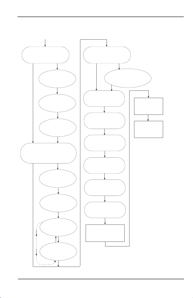
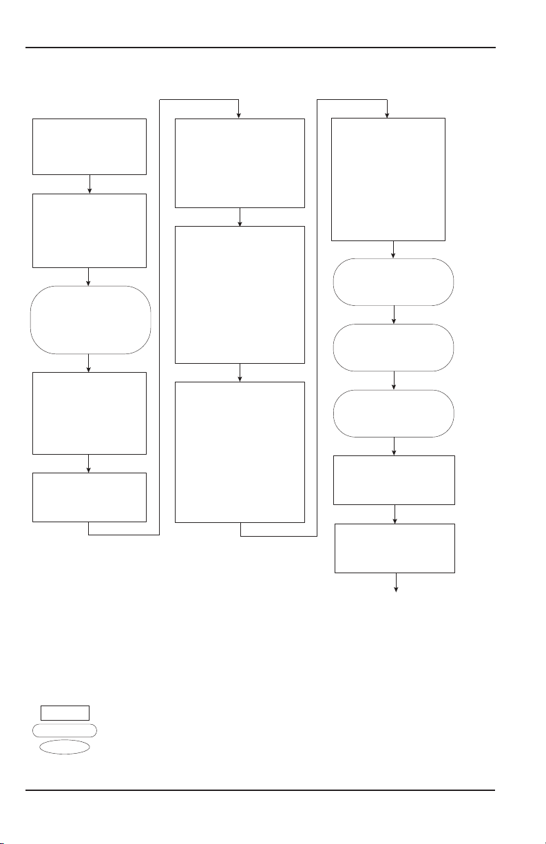
MENU STRUCTURE
Liquid
Fluid
Meter (Size)
Numeric Entry
KFactor
(K-Factor Value)
KFacUnt
(K-Factor Unit)
MASS
Display (Options)
START
Basic Menu
Extended Menu
Sub Menu
Liquid
Gas
0.250
0.375
0.500
0.625
0.750
0.875
1.0
1.25
1.5
Flow
Flow GT = Grand Total
Test
2.0
3.0
4.0
6.0
8.0
10.0
1225
1250
1275
Pul/Gal
Pul/m³
Pul/Ltr
Pul/Ft³
=
=
=
=
Pulses/Gallon
Pulses/meter³
Pulses/Liter
Pulses/Ft³
=
=
=
=
Sec
Min
Hour
Day
Second
Minute
Hour
Day
RateInt
(Rate time interval)
RateUnt
(Unit/interval=T)
GPT
LB/T
OB/T
AF/T
ML/T
LPT
m³/T
Ft³/T
MG/T
Kg/T
Lb/T
=
=
=
=
=
=
=
=
=
=
=
Gallons/T
Liquid Barrel/T
Oil Barrel/T
Acre Feet/T
Million Liters/T
Liters/T
Meters³/T
Feet³/T
Million
Gallons/T
Kilograms/T
Pounds/T
MASS
TotalUnt
(Totalizer Unit)
Gal
LBL
OBL
AFt
MLt
LPT
m³
Ft³
MGa
Kgs
Lbs
=
=
=
=
=
=
=
=
=
=
=
Gallons
Liquid Barrel
Oil Barrel
Acre Feet
Million Liters
Liters
Meters³
Feet³
Million
Gallons
Kilograms
Pounds
Menu item appears
only when MASS
units are selected.
Continued at B
on next page.
Shape Key
Rate SU
(Rate Unit Setup)
Simple Advanced
RateUnt
(Rate/Total Units)
GPM
Gal
OB/D
m³/D
m³
m³/H
m³
LPM
Ltr
=
=
=
=
=
=
=
=
=
Gallons/Min
Gallons
Oil Barrel/Day
Meters³/Day
Meters³
Meters³/Hour
Meters³
Liters/Min
Liters
Continued at A
on next page.

Menu Structure
Page 15April 2018 DSY-PM-00022-EN-14
Liquid (continued)
4-20Cal
(Calibrate 4-20)
Lin Pts = Linear Points (2 to10)
Linear
(Linearization)
Freq#1
(Frequency 1)
Clr G-T
(Clear Grand Total)
NO YES
4mA Out
(4 mA Output)
Numeric Entry
20mA Out
(20 mA Output)
Numeric Entry
4-20Tst
(4-20 mA Output)
Numeric Entry
Numeric Entry
Numeric Entry
Coef#1
(Coecient 1)
Numeric Entry
Freq#(x)
(Frequency 2-10)
Numeric Entry
Coef#(x)
(Coecent 2-10)
Numeric Entry
NO YES
Passwd
(Password)
Numeric Entry
RstPswd
(Reset Password)
Numeric Entry
Spec Gr
(Specic Gravity)
TotlMult
(Totalizer Multiplier)
× 1000
× 100
× 10
× 1
× 0.1
× 0.01
=
=
=
=
=
=
×1000
×100
×10
1
0.1
0.01
Numeric Entry
Scale F
(Scale Factor)
Numeric Entry
SetTotal
(Set Total Value)
Numeric Entry
Cuto
(Low Flow Cuto)
Numeric Entry
Damping
(Display Damping)
Numeric Entry
PulsOut
(Pulse Output)
Disable
Enable
Numeric Entry
Fl=20mA
(Flow at 20 mA)
Continued from B
on previous page.
Continued from A
on previous page.

Menu Structure
Page 16 April 2018DSY-PM-00022-EN-14
Advanced I/O Liquid
Fluid
Meter (Size)
Numeric Entry
KFactor
(K-Factor Value)
KFacUnt
(K-Factor Unit)
Spec Gr
(Specic Gravity)
MASS
Display (Options)
START
Basic Menu
Extended Menu
Sub Menu
Liquid
Gas
0.250
0.375
0.500
0.625
0.750
0.875
1.0
1.25
1.5
Flow
Flow GT = Grand Total
Test
2.0
3.0
4.0
6.0
8.0
10.0
1225
1250
1275
Pul/Gal
Pul/m³
Pul/Ltr
Pul/Ft³
=
=
=
=
Pulses/Gallon
Pulses/meter³
Pulses/Liter
Pulses/Ft³
=
=
=
=
Sec
Min
Hour
Day
Second
Minute
Hour
Day
RateInt
(Rate time interval)
RateUnt
(Unit/interval=T)
GPT
LB/T
OB/T
AF/T
ML/T
LPT
m³/T
Ft³/T
MG/T
Kg/T
Lb/T
=
=
=
=
=
=
=
=
=
=
=
Gallons/T
Liquor Barrel/T
Oil Barrel/T
Acre Feet/T
Million Liters/T
Liters/T
Meters³/T
Feet³/T
Million
Gallons/T
Kilograms/T
Pounds/T
MASS
TotalUnt
(Totalizer Unit)
Gal
LBL
OBL
AFt
MLt
LPT
m³
Ft³
MGa
Kgs
Lbs
=
=
=
=
=
=
=
=
=
=
=
Gallons
Liquor Barrel
Oil Barrel
Acre Feet
Million Liters
Liters
Meters³
Feet³
Million
Gallons
Kilograms
Pounds
TotlMult
(Totalizer Multiplier)
× 1000
× 100
× 10
× 1
× 0.1
× 0.01
=
=
=
=
=
=
×1000
×100
×10
1
0.1
0.01
Numeric Entry
Scale F
(Scale Factor)
Numeric Entry
SetTotal
(Set Total Value)
Numeric Entry
Cuto
(Low Flow Cuto)
Numeric Entry
Damping
(Display Damping)
Numeric Entry
PulsOut
(Pulse Output)
Disable
Enable
Numeric Entry
Fl=20mA
(Flow at 20 mA)
Menu item appears
only when MASS
units are selected. Continued on
next page.
Shape Key
Menu Structure
Page 17April 2018 DSY-PM-00022-EN-14
Advanced I/O Liquid (continued)
4-20Cal
(Calibrate 4-20)
Lin Pts = Linear Points (2 to10)
Linear
(Linearization)
Freq#1
(Frequency 1)
Modbus Address (1 to127)
BusAddr
Clr G-T
(Clear Grand Total)
Passwd
Password
NO YES
4mA Out
(4 mA Output)
Numeric Entry
20mA Out
(20 mA Output)
Numeric Entry
4-20Tst
(4-20 mA Output)
Numeric Entry
Numeric Entry
Numeric Entry
Coef#1
(Coecient 1)
Numeric Entry
Freq#(x)
(Frequency 2-10)
Numeric Entry
Coef#(x)
(Coecent 2-10)
Numeric Entry
Modbus
Disable Enable
Numeric Entry
SetPT1
(Setpoint 1)
Numeric Entry
Passwd
Password
HystSP1
(Hysteresis1)
Numeric Entry
Passwd
Password
TripSP1
(Trip On 1)
High Low
Passwd
Password
SetPT2
(Setpoint 2)
Numeric Entry
Passwd
Password
HystSP2
(Hysteresis2)
Numeric Entry
Passwd
Password
TripSP2
(Trip On 2)
High Low
NO YES
Passwd
(Password)
Numeric Entry
RstPswd
(Reset Password)
Numeric Entry
Continued from previous page.
Menu Structure
Page 18 April 2018DSY-PM-00022-EN-14
Gas
Fluid
Meter (Size)
Numeric Entry
KFactor
(K-Factor Value)
KFacUnt
(K-Factor Unit)
Display (Options)
START
Basic Menu
Extended Menu
Sub Menu
Liquid
Gas
Flow
Flow GT = Grand Total
Test
2.0 in. Low
2.0 in. Med
2.0 in. High
Pul/m³
Pul/Ltr
Pul/Ft³
=
=
=
Pulses/meter³
Pulses/Liter
Pulses/Ft³
=
=
=
=
Sec
Min
Hour
Day
Second
Minute
Hour
Day
RateInt
(Rate time interval)
RateUnt
(Unit/interval=T)
SCF/T
ACF/T
Nm³/T
Am³/T
Lt/T
mmF³/T
mF³/T
=
=
=
=
=
=
=
Standard Ft³/T
Actual Ft³/T
Normal M³/T
Actual M³/T
Liters/T
Million Ft³/T
Thousand Ft³/T
Shape Key
Continued on next page.
TotlUnt
(Totalizer Unit)
SCF
ACF
Nm³
Am³
Lt
mmF³
mF³
=
=
=
=
=
=
=
Standard Ft³
Actual Ft³
Normal M³
Actual M³
Liters
Million Ft³
Thousand Ft³
TotlMult
(Totalizer Multiplier)
× 1000
× 100
× 10
× 1
× 0.1
× 0.01
=
=
=
=
=
=
×1000
×100
×10
1
0.1
0.01
Scale F
(Scale Factor)
Numeric Entry
SetTotal
(Set Total Value)
Numeric Entry
Cuto
(Low Flow Cuto)
Numeric Entry
Numeric Entry
Op Pres
(Operating Pressure psi)
Numeric Entry
Op Temp
(Operating Temp °F)

Menu Structure
Page 19April 2018 DSY-PM-00022-EN-14
Gas (continued)
4-20Cal
(Calibrate 4-20)
Lin Pts = Linear Points (2 to10)
Linear
(Linearization)
Freq#1
(Frequency 1)
Clr G-T
(Clear Grand Total)
NO YES
4mA Out
(4 mA Output)
Numeric Entry
20mA Out
(20 mA Output)
Numeric Entry
4-20Tst
(4-20 mA Output)
Numeric Entry
Numeric Entry
Numeric Entry
Coef#1
(Coecient 1)
Numeric Entry
Freq#(x)
(Frequency 2-10)
Numeric Entry
Coef#(x)
(Coecent 2-10)
Numeric Entry
NO YES
Passwd
(Password)
Numeric Entry
RstPswd
(Reset Password)
Numeric Entry
Continued from
previous page.
Damping
(Display Damping)
Numeric Entry
PulsOut
(Pulse Output)
Disable
Enable
Numeric Entry
Fl=20mA
(Flow at 20 mA)

Menu Structure
Page 20 April 2018DSY-PM-00022-EN-14
Advanced I/O Gas
Fluid
Meter (Size)
Numeric Entry
KFactor
(K-Factor Value)
KFacUnt
(K-Factor Unit)
Display (Options)
START
Basic Menu
Extended Menu
Sub Menu
Liquid
Gas
Flow
Flow GT = Grand Total
Test
2.0 in. Low
2.0 in. Med
2.0 in. High
Pul/m³
Pul/Ltr
Pul/Ft³
=
=
=
Pulses/meter³
Pulses/Liter
Pulses/Ft³
=
=
=
=
Sec
Min
Hour
Day
Second
Minute
Hour
Day
RateInt
(Rate time interval)
RateUnt
(Unit/interval=T)
SCF/T
ACF/T
Nm³/T
Am³/T
Lt/T
mmF³/T
mF³/T
=
=
=
=
=
=
=
Standard Ft³/T
Actual Ft³/T
Normal M³/T
Actual M³/T
Liters/T
Million Ft³/T
Thousand Ft³/T
Shape Key
Continued on next page.
TotlUnt
(Totalizer Unit)
SCF
ACF
Nm³
Am³
Lt
mmF³
mF³
=
=
=
=
=
=
=
Standard Ft³
Actual Ft³
Normal M³
Actual M³
Liters
Million Ft³
Thousand Ft³
TotlMult
(Totalizer Multiplier)
× 1000
× 100
× 10
× 1
× 0.1
× 0.01
=
=
=
=
=
=
×1000
×100
×10
1
0.1
0.01
Scale F
(Scale Factor)
Numeric Entry
SetTotal
(Set Total Value)
Numeric Entry
Cuto
(Low Flow Cuto)
Numeric Entry
Numeric Entry
Op Pres
(Operating Pressure psi)
Numeric Entry
Op Temp
(Operating Temp °F)
Other manuals for B3000
1
Table of contents
Other Blancett Monitor manuals


