manuals.online logo
Brands
  1. Home
  2. •
  3. Brands
  4. •
  5. Blaupunkt
  6. •
  7. Car Receiver
  8. •
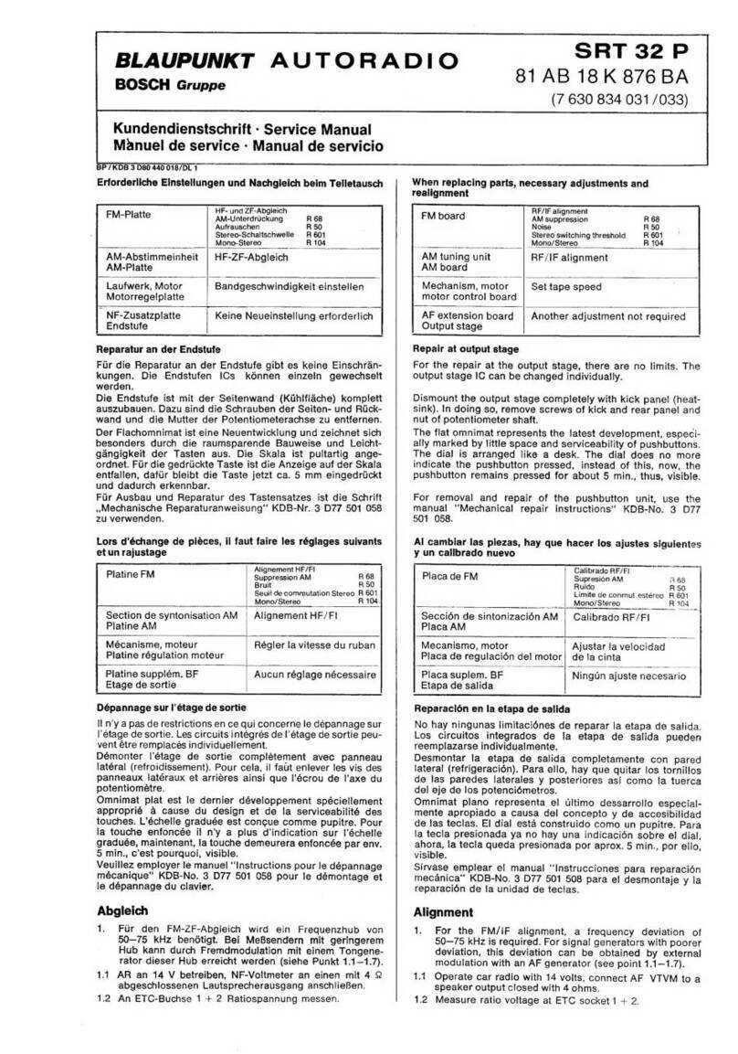
  9. Blaupunkt Frankfurt RCM 104 Guide

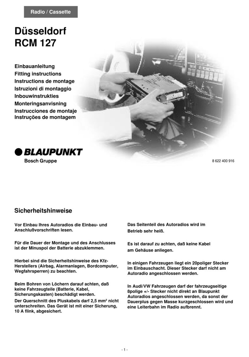
Blaupunkt Frankfurt RCM 104 Guide

Other Blaupunkt Car Receiver manuals

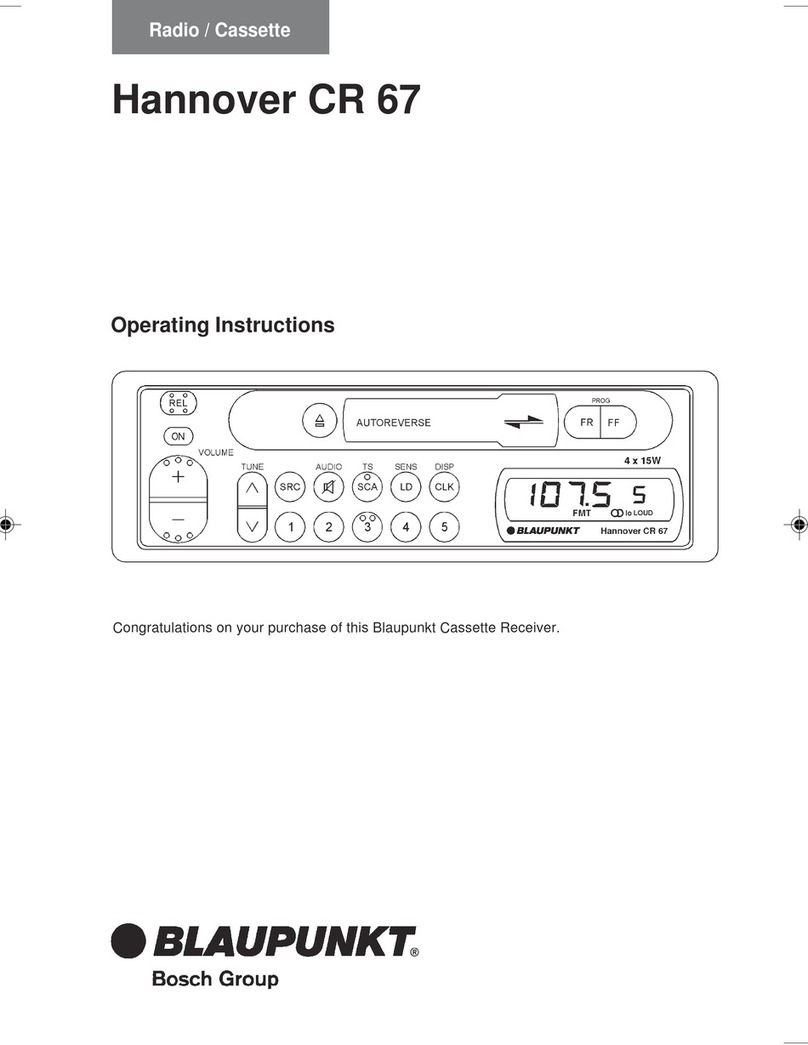
Blaupunkt Verona CR 43 User manual

Blaupunkt

Blaupunkt Verona CR 43 User manual

Blaupunkt TEV-501 User manual

Blaupunkt

Blaupunkt TEV-501 User manual

Blaupunkt KOPENHAGEN RCR 45 User manual

Blaupunkt

Blaupunkt KOPENHAGEN RCR 45 User manual

Blaupunkt Munchen RD 104 User manual

Blaupunkt

Blaupunkt Munchen RD 104 User manual

Blaupunkt Ventura CD83 User manual

Blaupunkt

Blaupunkt Ventura CD83 User manual

Blaupunkt GRENOBLE RD 169 User manual

Blaupunkt

Blaupunkt GRENOBLE RD 169 User manual

Blaupunkt Sacramento CD33 User manual

Blaupunkt

Blaupunkt Sacramento CD33 User manual

Blaupunkt SEVILLA MP38 User manual

Blaupunkt

Blaupunkt SEVILLA MP38 User manual

Blaupunkt TravelPilot E1 User manual

Blaupunkt

Blaupunkt TravelPilot E1 User manual

Blaupunkt BOSCH GRUPPE RMD 169 User manual

Blaupunkt

Blaupunkt BOSCH GRUPPE RMD 169 User manual

Blaupunkt BPV 655 User manual

Blaupunkt

Blaupunkt BPV 655 User manual

Blaupunkt BPV 660 User manual

Blaupunkt

Blaupunkt BPV 660 User manual

Blaupunkt Key West MP36 User manual

Blaupunkt

Blaupunkt Key West MP36 User manual

Blaupunkt RDM 169 US User manual

Blaupunkt

Blaupunkt RDM 169 US User manual

Blaupunkt Acapulco CD51 User manual

Blaupunkt

Blaupunkt Acapulco CD51 User manual

Blaupunkt MEMPHIS MP66 Specification sheet

Blaupunkt

Blaupunkt MEMPHIS MP66 Specification sheet

Blaupunkt KIEL CD36 User manual

Blaupunkt

Blaupunkt KIEL CD36 User manual

Blaupunkt NEW JERSEY 220 BT User manual

Blaupunkt

Blaupunkt NEW JERSEY 220 BT User manual

Blaupunkt Laguna CD43 User manual

Blaupunkt

Blaupunkt Laguna CD43 User manual

Blaupunkt SYDNEY Sydney RCM 126 User manual

Blaupunkt

Blaupunkt SYDNEY Sydney RCM 126 User manual

Blaupunkt 1 011 200 344 User manual

Blaupunkt

Blaupunkt 1 011 200 344 User manual

Blaupunkt Miami beach cd51 Specification sheet

Blaupunkt

Blaupunkt Miami beach cd51 Specification sheet

Blaupunkt TOKYO 110 User manual

Blaupunkt

Blaupunkt TOKYO 110 User manual

Blaupunkt CALGARY MP35 User manual

Blaupunkt

Blaupunkt CALGARY MP35 User manual

Popular Car Receiver manuals by other brands

Linear Series LS5050 Operation and installation manual

Linear Series

Linear Series LS5050 Operation and installation manual

Kenwood KRC-160 instruction manual

Kenwood

Kenwood KRC-160 instruction manual

Sony XR-CA430X Service manual

Sony

Sony XR-CA430X Service manual

T+A Elektroakustik K1 CD-RECEIVER operating instructions

T+A Elektroakustik

T+A Elektroakustik K1 CD-RECEIVER operating instructions

SoundMax SM-CDM1052 instruction manual

SoundMax

SoundMax SM-CDM1052 instruction manual

Xtrons HD107HD user manual

Xtrons

Xtrons HD107HD user manual

Mopar RB3 manual

Mopar

Mopar RB3 manual

Clarion ADDZEST DMZ615 owner's manual

Clarion

Clarion ADDZEST DMZ615 owner's manual

Sony XAV-601BT Specifications

Sony

Sony XAV-601BT Specifications

PIE GM12-POD/S Operation manual

PIE

PIE GM12-POD/S Operation manual

Hyundai H-910H instruction manual

Hyundai

Hyundai H-910H instruction manual

Sony XR-C6100 Service manual

Sony

Sony XR-C6100 Service manual

Sony CDX-L600X - Fm/am Compact Disc Player Installation/connections

Sony

Sony CDX-L600X - Fm/am Compact Disc Player Installation/connections

Motorola VWA63 Service manual

Motorola

Motorola VWA63 Service manual

Sound Storm STM93R user manual

Sound Storm

Sound Storm STM93R user manual

Nextar D3201 instruction manual

Nextar

Nextar D3201 instruction manual

Alpine CDE-163BT owner's manual

Alpine

Alpine CDE-163BT owner's manual

Kenwood KDC-X303 quick start guide

Kenwood

Kenwood KDC-X303 quick start guide

manuals.online logo
manuals.online logoBrands
  • About & Mission
  • Contact us
  • Privacy Policy
  • Terms and Conditions

Copyright 2025 Manuals.Online. All Rights Reserved.

- 1 -
Sicherheitshinweise
Einbau- und Anschlußvorschriften
Für die Dauer der Montage und des Anschlusses
ist der Minuspol der Batterie abzuklemmen.
Hierbei sind die Sicherheitshinweise des Kfz-
Herstellers (Airbag, Alarmanlagen, Bordcomputer,
Wegfahrsperren) zu beachten.
Beim Bohren von Löchern darauf achten, daß
keine Fahrzeugteile (Batterie, Kabel,
Sicherungskasten) beschädigt werden.
Der Querschnitt des Pluskabels darf 2,5 mm2nicht
unterschreiten. Das Gerät ist mit einer Sicherung,
10 A flink, abgesichert.
Das Seitenteil des Autoradiogehäuses wird im
Betrieb sehr heiß.
Achtung: Es ist darauf zu achten, daß keine Kabel
am Gehäuse anliegen.
8 622 400 282
FRANKFURT
Einbauanleitung
Fitting instructions
Instructions de montage
Istruzioni di montaggio
Inbouwinstrukties
Monteringsanvisning
Instrucciones de montaje
Instruções de montagem
Frankfurt
RCM 104
TIM
Radio / Cassette
- 2 -
D
Anschluß mit fahrzeugseitigen Systemsteckern
Fahrzeugseitige Plus-/ Minus-Systemstecker nicht
verwenden.
Für den Plus- / Minusanschluß das Anschlußkabel 7 607 884 093
verwenden, Fig. 4, 5.
In einigen Mercedes-Fahrzeugen liegt ein 10poliger Stecker im Einbau-
schacht.DieserSteckerdarfnichtamAutoradioangeschlossenwerden,
da sonst der Schaltplus für Antenne/Verstärker gegen Masse kurzge-
schlossen wird und eine Leiterbahn im Radio aufbrennt.
Hinweis:
Die zum Lieferumfang dieses Autoradios gehörende Halterung ermög-
licht den Einbau in Fahrzeugen mit DIN-Autoradioausschnitt von
182 x 53 mm,165 mmEinbauraumundeinerInstrumententafeldickeim
Bereich der Befestigungslaschen von 1 - 20 mm, siehe Fig. 1.
Für Fahrzeuge mit abweichender Einbausituation liefert Blaupunkt für
die gängigsten Fahrzeuge fahrzeugspezifische Einbausätze für 50 mm
Geräte.
Prüfen Sie daher, ob die Einbausituation im Fahrzeug vorliegt, und
verwendenSiezumEinbaugegebenenfallseinenfahrzeugspezifischen
Einbausatz, z. B. Audi A4/A6/A8: 7 608 0214 73.
Autoradioeinbauvorbereitung
Das Autoradio wird in den vom Fahrzeughersteller vorgesehenen
Autoradioausschnitt eingebaut.
Autoradioausschnittfreilegen(AblagefachoderBlindblendeausclipsen)
oder Autoradioausschnitt auf 182 x 53 mm ausarbeiten.
HinterdenAutoradioausschnittfassenundprüfen,welcheBefestigungs-
laschen der Halterung umgebogen werden können.
Hinweis: Möglichst alle Befestigunglaschen umbiegen.
Halterung in den Ausschnitt einsetzen und die Befestigungslaschen mit
einem Schraubendreher umbiegen, siehe Fig. 1, 2.
Anschluß
Anschlußhinweise........................................................................ Fig. 4
Plus-/Minus-Anschluß.................................................................. Fig. 5
Equalizer- und Amplifieranschluß................................................ Fig. 6
Dem Amplifier beiliegendes Anschlußkabel oder Anschlußblock
7 607 874 003 verwenden.
Lautsprecheranschluß: 4 Lautsprecher (4 Ω/25 W) .................... Fig. 7
Anschluß CD-Player ................................................................. Fig. 8/9
Dem CD-Changer beiliegendes Anschlußkabel oder Anschlußblock-
verwenden.
Anschluß IR-Fernbedienung RC-05 .......................................... Fig. 10
Das beiliegende Anschlußkabel der IR-Fernbedienung verwenden.
BeiBedarf könnendieAnschlußkabel 7 607 647 093 und 7 607 648 000
zusätzlich verwendet werden.
Bei Verwendung der IR-Fernbedienung ist ein QuickOut-Betrieb nicht
möglich.
Anschluß mit fahrzeugseitigem QuickOut
Bei Fahrzeugen, die fahrzeugseitig mit QuickOut ausgerüstet sind
(z.Z. Opel), muß die fahrzeugseitige QuickOut ausgebaut werden.
Autoradioeinbau
Autoradio von vorn in die Halterung einsetzen und einschieben, bis die
seitlichen Rastfedern rechts und links arretieren (deutliches Knacken
hörbar).
Autoradioausbau
Bügel links und rechts in die vorhandenen Löcher der Blende stecken
und so weit eindrücken, bis deutliches Knacken zu hören ist (seitliche
Federn entriegelt).
Gerät an den beiden Bügeln herausziehen, siehe Fig. 3.
Hinweis: Eingerastete Bügel können nur nach Herausziehen
des Gerätes entfernt werden.
Änderungen vorbehalten!
Illustrationen / Illustrations / Ilustraciones / Illustrazioni / Illustrationer / Afbeeldingen / Ilustraçoes
53
182
165
8 601 310 742
1-20
Fig. 1
Fig. 2
8 601 910 002
2
2
1
1
Fig. 3
Die Ersatzteile (8 ... ... ...) sind über den zentralen Ersatzteilversand (VKD3), Ulmer Straße, 3014 Laatzen 1, zu beziehen. / Spare parts (8 ... ... ...) are obtained via central parts dispatch: (VKD3),
Ulmer Straße, 3014 Laatzen 1. / Pour la fourniture des pièces de rechange (8 ... ... ...), s’adresser au centre des pièces détachées, (VKD3), Ulmer Straße, 3014 Laatzen 1.
- 3 -
Anschlußhinweise, Fig. 4
Masseanschluß (Ground)
Massekabel nicht am Minuspol der Batterie anklemmen.
Massekabel zu einem geeigneten Massepunkt verlegen
(Karosserieschraube, Karosserieblech) und entsprechend
Massepunkt kürzen. Massekabel abisolieren und Krallen-
kabelschuh anschlagen (ggf. nachlöten). Kontaktfläche des
Massepunktes metallisch blank kratzen und mit Graphitfett
einfetten (wichtig für gute Masseverbindung).
Massekabel anschrauben.
Pluskabelanschluß (ACC + 12 V)
(Ignition) +12V
Wird das Pluskabel am Sicherungshalter Kl.15
(PlusüberZündschloßgeschaltet)hinterderSicherungange-
schlossen,soistdasEin-undAusschaltendesAutoradiosüber
Zündung möglich.
Außerdemschaltetdas GerätzumSchutz der Batterieautoma-
tisch nach einer Stunde aus.
Die Stunden-Logik wird nicht aktiviert, wenn Dauerplus (Kl.30)
angeschlossen wird.
Dauerplusanschluß (Battery + 12 V) per. +12V
FahrzeugseitigesPluskabelnichtanschließen.
Pluskabel (rot) mit starkem Querschnitt (2,5 mm2) zur Batterie
verlegen (Kabel nicht unmittelbar an Kabelbäumen verlegen).
SicherungshalterzurAbsicherung des Pluskabels anschließen
undamPluspolderBatterieanklemmen(ggf.LochinSpritzwand
bohren und entsprechend Kabeldurchführung verwenden).
Steuerkabel (Power Antenna +)
+12V
Das Steuerkabel ist der geschaltete Plusausgang für
externe Komponenten z.B.: Motorantenne.
Das Steuerkabel nicht an Klemme 15 (Plus geschaltet) oder
Klemme 30 (Dauerplus) anschließen.
Steuerkabel (Amplifier)
+12V
Das Steuerkabel ist der geschaltete Plusausgang für
externe Komponenten z.B.: Verstärker/Equalizer.
Das Steuerkabel nicht an Klemme 15 (Plus geschaltet) oder
Klemme 30 (Dauerplus) anschließen.
Beleuchtungsanschluß (Illumination)
Beleuchtungsanschluß für Fahrzeuge mit regelbarer
Instrumentenbeleuchtung (plusgeregelt).
Telefon Mute (low)
Bei Anschluß eines Telefons wird das Autoradio während des
Telefonierens stummgeschaltet.
Störfreier Massepunkt
5A
+
1
23
5A
5A
+12V
Kl. 15
Kl.30
12V
5A
5A
PIN6
gr
br
rt
rt
or
bl
ge/gn
Kl.30
12V
15A
per +12V
5A
PIN 4
5A
- 4 -
Fig. 4
Fig. 5
7 607 874 090
Fig. 6
REAR
7 607 886 093
5m
ws
rt
ws
rt
LR/RR
LF/RF
FRONT
bl
+12V
ws
rt
rt
Amplifier Equalizer
LR
RR
RF
LF
ws
5A
7 607 855 094
Amplifier Equalizer
7 607 863 001
Preamp Out
LR
RR
RF
LF
5m
5A
oder/or/ou
2
1
3
+12V
per.+12V
+12V
7 607 884 093
br
ge/gn
or
rt
rt
5A
15A
Kl. 15
12V
per.+12V
Kl. 30
15
7,5
7,5
7,5
10
8 600 660 006
8 604 390 045
- 5 -
5A
LR
RR
RF
LF
RRRF LF LR
+
-
+
-
+
-
+
-
7 607 882 090
LF
RF
LR
RR
LR
RR
RF
LF
Fig. 7
Die Ersatzteile (8 ... ... ...) sind über den zentralen Ersatzteilversand (VKD3), Ulmer Straße, 3014 Laatzen 1, zu beziehen. / Spare parts (8 ... ... ...) are obtained via central parts dispatch: (VKD3),
Ulmer Straße, 3014 Laatzen 1. / Pour la fourniture des pièces de rechange (8 ... ... ...), s’adresser au centre des pièces détachées, (VKD3), Ulmer Straße, 3014 Laatzen 1.
Fig.7
Bus/NF
Fig.4/5
gr
rt
ge/gn
br
rt
or
CDC A05
LF
RF
LR
RR
Si 3A
5A
Fig.6
Fig.4
Fig. 8 oder/or/ou
8 604 390 087
8 619 309 076
8 619 309 068
Si 3A
ws
rt
ws
rt
li
+
++
+
ws
gn
+
gr
Bus
5A
rt
bl
FRONT
REAR
REAR L
FRONT L
REAR R
+12V
FRONT RFRONT R
br
or
ge/gn
gr
BATT
CDC A05
rt
Fig.4
Fig.4/5
Fig.7
Fig.6
- 6 -
PIN 6
LF
RF
LR
RR
Si 3A
5A
Cinch/L
Cinch/R
Bus
rt
ws
Changer
Interface
rt
per.+12V
ws
rt
R 30mm
br
rt CDC F05
R 30mm
Fig.4/5
gr
rt
ge/gn
br
rt
or
Fig.7
Fig.6
Fig.4
+12V
Fig. 10
oder /or /ou
Fig. 9
8 619 399 716
8 619 399 718
8 619 399 717
8 619 309 068
Si 3A
ws
rt
ws
rt
li
+
++
+
ws
gn
+
gr
Bus
5A
bl
Cinch/L
Cinch/R
ws
rt
INPUT
Fig.6
FRONT
REAR
REAR L
FRONT L
FRONT R
REAR R
rt
ws
CDC F05
R 30mm
R 30mm
Changer
Interface
rt
per.+12V
br
rt
br
or
ge/gn
gr
BATT
rt
Fig.7
Fig.4
Fig.4
Fig.4/5
Amplifier
Equalizer
Changer
+12V
LR
RR
RF
LF
2
1
3
12V
5A
+12V
per.+12V
+12V
7 607 647 093
7 607 648 000
7 607 884 093
LF
RF
LR
RR
15A
- 7 -
Connection with QuickOut installed ex factory
If your car is fitted with a QuickOut ex factory (at present Opel), the
QuickOut ex factory has to be removed.
Car radio installation
Insert the car radio from the front into the support and push in until the
stopspringsonthesidesengagerightandleft(distinctclicktobeheard).
Removal of the car radio
Insert the brackets right and left into the provided trimplate holes and
push in until you hear a distinct click (lateral springs are unlocked).
Using both brackets (see fig. 3), pull the unit out.
Note
Locked brackets can only be removed after taking out the unit.
Notes on connection, fig. 4
Ground cable "br"
Do not connect the ground cable to the negative pole of the battery.
Route the ground cable to a suitable ground point (car body screw, car
body metal sheet) and shorten it accordingly.
Removetheinsulationfromthegroundcableandattachtheforkedcable
lug (if necessary, solder it).
Scratch off the paint from the contact area of the ground point and
lubricate it with graphite grease (important for good ground contact).
Screw on the ground cable.
Positive cable (ACC + 12 V) (ignition) "rt"
+12V
Ifthepluscableisconnectedtopin15ofthefuseholder(plusconnected
via ignition lock) downstream of the fuse, the in-car radio can be
switchedonandoffwiththeignitionkey.Inaddition,thesetautomatically
switches off after one our in order to avoid that the battery goes flat.
Thehourlogicwillnotbeactivatedwhrnconnectingthepermanent+12 V
line (terminal 30).
Permanent plus connection (Battery +12 V) "rt"
per. +12V
Do not use the positive cable installed in the car.
Routethepositivecable(thickredcableof2.5 mm2)tothebattery(donot
route the cable near the cable harnesses). Connect the fuse holder to
protectthepositivecableandconnectittothepositivepoleofthebattery
(if necessary, drill a hole into the fire wall and use cable ducts).
Control cable (Power Antenna +) "ge/gn"
+12V
The control cable represents the switched positive output for external
components, e.g. motor antennas.
Do not connect the control cable to pin 15 (switched +) or pin 30
(permanent +12 V).
Control cable (Amplifier) "bl"
+12V
The control cable represents the switched positive output for external
components, e.g. amplifiers, equalizers.
Do not connect the control cable to pin 15 (switched +) or pin 30
(permanent +12 V).
Lighting connection (Illumination) "or"
Lightingconnectionforvehicleswithadjustabledashboardlighting(plus-
controlled).
Telephone mute (Low) "gr"
Ifyouhaveconnectedacartelephone,yourcarradiowillbemutetduring
telephone calls.
Modifications reserved
GB
Notes on Safety
Instructions for installation and connection
Disconnect the battery ground wire during installation and connection.
When drilling a hole, be sure not to damage any vehicle part (battery,
cable, fuse, etc.).
Thepositivecablemusthaveacross-sectionofatleast2,5 mm2.Theunit
isprotectedbyaquick-actingfuseof10 A.Donot use the positive cable
installed ex factory.
The side panel of the car radio heats up considerably during
operation.
Attention: Pay attention that the cables do not contact with the
housing.
Connection with in-vehicle system plugs
Do not use the positive/negative system
connectors provided in the vehicle!
For connecting all positive and negative wiring, use connection
cable 7 607 884 093, fig. 4, 5.
Some Mercedes vehicles are equipped with a 10-pin connector located
in the installation compartment.
This connector must not be hooked up to car radio, since otherwise the
positive supply line feeding the antenna or amplifier would be short-
circuited to ground! As a result, one of the conductive tracks in the radio
would start burning.
Note:
By means of the support included in the delivery you can mount the set
in cars with a DIN car radio cut-outout of 182 x 53 mm, an installation
depth of 165 mm and an instrument panel thickness around the fixing
clips of 1 - 20 mm, see fig. 1.
For cars with other cut-out dimensions Blaupunkt delivers car-specific
installation kits for common car types for 50/52 mm sets.
Please check the dimensions and, if necessary, use a car-specific
installation kit, e. g. Audi A4/A6/A8: 7 608 0214 73.
Whenusinginstallationsetsforunitsof52mmfourdistanceplates,order
number 8 601 055 056, must be used, fig. 1a.
Preparation of car radio installation
Installthecarradio intotheDINcut-outprovidedinyourcar’sdashboard
ex factory.
Prepare the car radio DIN cut-out (unlock shelf or dummy cover) or cut
out the car radio compartment to 182 x 53 mm.
Grasp behind the car radio cut-out and check how many of the fixing
strips of the car radio support can be bent.
Note:
Try to bend as many fixing strips as possible.
Insert the support into the cut-out and bend the appropriate fixing strips
with a screwdriver, see fig. 1, 2.
Connection
Notes on connection ...................................................................... fig.4
Plus/minus-Connection................................................................. fig. 5
Connection of equalizer and amplifier .......................................... fig. 6
Use the adapter cable enclosed to the amplifier or the adaptercable
7 607 874 003.
Loudspeaker connection:
4 speakers (4 Ω/25 W).................................................................. fig. 7
Connection of CD-Player ........................................................... fig. 8/9
Use the adapter cable enclosed to the CD-Changer or the connecting
block.
Connection of IR remote control RC-05 .................................... Fig. 10
Use the connection cable attached to the remote control. If necessary,
also use cables 7 607 647 093 and 7 607 648 000.
When using the IR remote control, QuickOut operation is not possible.
8 622 400 282
- 8 -
F
Notes de sécurité
Instructions de montage et de branchement
Pendant le montage et le branchement des appareils, il convient de
déconnecter le pôle négatif de la battérie.
Veiller à ce qu’aucun élément de voiture (tel que la battérie, les câbles,
les porte-fusibles) ne soit endommagé par le perçage des trous).
Lasectionducâblepositifnedoitpasêtreinférieureà2,5mm2.L’appareil
estprotégéparl’intermédiaired’unfusibleàdéclenchementrapide10A.
Ne pas utiliser le câble positif installé de l’usine.
Le panneau latéral de l’autoradio s’échauffe considérablement
pendant l’opération.
Attention: Alors faire attention qu’aucun câble ne touche le boîtier.
Connexion avec les connecteurs système prévus dans le
véhicule
Ne pas utiliser les connecteurs positifs/négatifs
prévus dans le véhicule.
Utiliser le câble de raccordement 7 607 884 093 pour réaliser la
connexion, voir figs. 4, 5.
Dans certains véhicules Mercedes, une fiche à 10 pôles se trouve dans
le compartiment.
Cette fiche ne doit pas être connectée à l’autoradio; sinon le positif de
connexion pour l’antenne/l’amplificateur donnera court-circuit à la mas-
se et une piste conductive dans l’autoradio brûlera.
Note:
A l’aide du support inclus dans le jeu de montage vous pouvez monter
leposte dansdesvoituresqui disposentd’unedécoupe DINde182 x53
mm,d’uneprofondeurde 175mm etd’uneépaisseurdutableaudebord
de 5,2 - 6,3 mm autour des éclisses de montage, voir fig. 1.
Blaupunktlivredesjeuxdemontagespéciauxpourlesvoiturescourantes
avec des découpes différentes pour les appareils 50/52 mm.
Veuillez donc vérifier les mesures de la découpe de votre voiture et, si
nécessaire, commander un jeu de montage spécial, p. ex. Audi A4/A6/
A8: 7 608 0214 73.
Enutilisantdesjeuxd’installationpourdespostesde52mmilfaututiliser
4 plaques de distance, numéro de référence 8 601 055 056, fig. 1a.
Préparation pour l’installation d’autoradio
Monter l’autoradio dans la découpe autoradio prévue d’origine.
Ouvrir la découpe autoradio (dégager le compartiment ou le cache
factice) ou élargir la découpe à 182 x 53 mm.
Saisir derrière la découpe autoradio et essayer lesquelles des éclisses
de montage peuvent être courbées.
Note: si possible, courber toutes les éclisses de montage.
Insérerlesupportdansladécoupeetcourberleséclissescorrespondantes
à l’aide d’un tournevis, voir fig. 1 et 2.
Raccordement
Indication pour le raccordement ................................................... fig. 4
Positive/negative-Raccordement.................................................. fig. 5
Raccordement de l’égaliseur et de l’amplificateur.........................fig. 6
Utiliserlecâbled´eadapteurinclusauAmplificateuroulecâbled’eadapteur
7 607 874 003.
Raccordement des haut-parleurs:
4 H-P (4 Ω/25 W) .......................................................................... fig. 7
Raccordement de CD-Player..................................................... fig. 8/9
Utiliser le câble d´eadapteur inclus au changer CD ou le bloc de
raccordement.
Raccordement de la télécommande IR RC-05...........................fig. 10
Utiliser le câble de raccordement livré avec la télécommande IR, le cas
échéant, le câble de raccordement 7 607 647 093 et 7 607 648 000.
L’emploi d’un tiroir extractible n’est pas possible en utilisant la
télécommande IR.
Branchement dans le cas d’un extractible monté dans la voiture
Lorsqu’ils’agitd’une voiture équipéed’unextractible(p. ex. Opel),ilfaut
démonter l’extractible monté dans la voiture.
Montage de l’autoradio
Insérerl’autoradiopardevantdanslesupportetpousserjusqu’àceque
les ressorts d’arrêt s’enclenchent à droite et à gauche (clic distinct
audible).
Démontage de l’autoradio
Insérerles étriers dans les trous préparés du cache à droite et àgauche
jusqu’à ce que vous entendiez un clic distinct (les ressorts latéraux sont
déverrouillés).
Retirer l’appareil à l’aide des deux étriers, voir fig.3.
Note
Des étriers verrouillés ne peuvent être enlevés qu’après avoir retiré
l’appareil.
Indications pour le raccordement, fig. 4
Câble de masse (Ground) "br"
Ne pas raccorder le câble de masse au pôle négatif de la batterie.
Faire passer le câble de masse à un point de masse approprié (boulon
de carrosserie, tôle de carrosserie) et raccourcir le câble à la longueur
convenable.
Enleverle matérielisolantdubout decâbleet attacherlacosse decâble
fourchée (si nécessaire, soudez-la).
Dégratter la peinture du point de masse et l’enduire d’une couche de
graisse à graphite (important pour une bonne connexion à la masse).
Visser le câble de masse.
Câble d’alimentation positive (ACC 12 V) "rt"
(ignition)
+12V
Lorsquelecâble plusestbranché sur laborne15 du porte-fusibles(plus
branché par l’intermédiaire de la serrure de contact) en aval du fusible,
l’autoradiopeutêtremise en/horsserviceàl’aidedelaclédecontact.En
plus, l’appareil se met automatiquement hors service au bout d’une
heure pour conserver la batterie.
La logique de mise hors service au bout d’une heure n’est pas activée
lorsque le plus permanent (borne 30) est connecté.
Raccordement au plus permanent "rt"
(Battery 12 V)
per. +12V
Ne pas raccorder le câble positif installé dans la voiture.
Poser le câble positif (câble rouge d’une épaisseur de 2,5 mm2) vers le
batterie(éviterdepasserlecâbleprèsdefaisceauxdecâbles).Raccorder
le porte-fusible pour protéger le câble positif et l’attacher au pôle de la
batterie (si nécessaire, percer un trou dans le tablier d’auvent et utiliser
un passe-câble approprié).
Câble de commande (Power Antenna +) "ge/gn"
+12V
Le câble de commande est la sortie positive connectée pour des
éléments externes, p.ex. antenne à moteur.
Ne pas connecter le câble de commande à la borne 15 (plus connecté)
ou à la borne 30 (plus permanent).
Câble de commande (Amplificateur) "bl"
+12V
Le câble de commande est la sortie positive connectée pour des
éléments externes, p.ex. amplificateur, égaliseur.
Ne pas connecter le câble de commande à la borne 15 (plus connecté)
ou à la borne 30 (plus permanent).
Conexion d’illumination (Illumination) "or"
Conexion d’illumination pour des véhicules à illumination du tableau de
bord réglable (réglé par positif).
Régulation en muet lors d'une conversation "gr"
téléphonique (Low)
Lorsqu´onbrancheuntéléphon,l'autoradioestautomatiquementrégléen
muet pendant la conversation téléphonique.
Modifications réservées.
- 9 -
I
Misure di sicurezza
Avvertenze di installazione e di collegamento
Perl’intera duratadell’installazionee delcollegamentodell’apparecchio
staccate di massa della batteria.
Durante la trappanatura dei fori, fate attenzione che nessuna parte del
veicolo (batteria, cavi, scatola dei fusibili) venga danneggiata.
Lasezionedel cavopositivonondeve superare2,5mm2.L’apparecchio
è assicurato con una sicurezza, 10 A flink.
La parte laterale dell’alloggaimento dell’autoradio si riscalda
fortemente durante l’esercizio della radio.
Attenzione:Perquesto motivo bisogna fareattenzione che nessun
cavo tocchi l’alloggiamento.
Collegamento con le spine del sistema già predisposte
nell’autovettura
Non usare la spina positiva e quella negativa
dell’autovettura.
Usare il cavo di collegamento 7 607 884 093, fig. 4 e 5, per
l’allacciamento al positivo e al negativo.
In alcune autovetture della Mercedes nel vano di montaggio vo si trova
una spina a 10 poli.
Questa spina non deve essere collegata all’autoradio. Altrimenti viene
cortocircuitata l’uscita a 12 V per l’antenna/l’amplificatore contro massa
e si brucia un conduttore nella radio.
Avvertenza:
Il supporto fornito in dotazione con quest’autoradio, ne consente il
montaggio in vetture con apertura per autoradio secondo norme DIN, di
182 x 53 mm, profundità di 165 mm ed uno spessore della plancia
portastrumento nella zona delle linguette di fissaggio, pari a 1 - 20 mm,
vedi fig. 1.
Perautovettureconinstallazioneradiodiversa,Blaupunktfornisceperle
vetture più communi pezzi specifici per apparacchi 50/52 mm.
Vogliatequindicontrollareselavetturainquestionepresentalecondizioni
sopradescritte;all’occorrenzaandràusatounkitdimontaggiospecifico,
per es. Audi A4/A6/A8: 7 608 0214 73.
Usando i set di montaggio per apparecchi di 52 mm è necessario
utilizzare 4 piastrine distanziatrici no. d’ordinazione 8 601 055 056, vedi
Fig. 1a.
Preparazioni per l’installazione dell’autoradio
L’autoradio viene montata nell’apertura appositamente prevista dal
costruttore della vettura.
Liberare l’apertura (staccare il ripiano portaoggetti o la mascherina
cieca), oppure allargare l’apertura a 182 x 53 mm.
Far passare la mano dietro all’apertura dell’autoradio e verificare quali
linguette di fissaggio del supporto possono venir piegate.
Avvertenza: Possibilmente piegare tutte le linguette di fissaggio.
Introdurreilsupportonell’aperturaepiegareopportunamentelelinguette
di fissaggio con un giraviti, vedi Fig. 1 e 2.
Collegamento
Avvertenze di collegamento ......................................................... fig. 4
Positivo/negativo-Collegamento ................................................... fig. 5
Collegamento dell’equillizzatore e dell’amplicatore.......................fig. 6
Utilizzate il cavo adattore oppure amplificatore il cavo adattore
7 607 874 003 fornito.
Collegamento degli altoparlanti:
4 altoparlanti (4 Ω/25 W) .............................................................. fig. 7
Collegamento CD-Player ........................................................... fig. 8/9
Utilizzate il cavo adattore oppure il blocco d´allacciamento fornito.
Allacciamento telecomando IR RC-05 ......................................Fig. 10
Fate uso del cavo di allacciamento accluso al telecomando IR,
eventualmenteconicavidiallacciamento7 607 647 093e7 607 648 000.
Quando si impiega il telecomando non è possibile far funzionare il
QuickOut.
Collegamento con un QuickOut specifico per la vettura
In autovetture equipaggiate già in produzione con un QuickOut (per il
momento la Opel), questo QuickOut deve esere smontado.
Installazione autoradio
Introdure anteriormente l’autoradio nel supporto e spingerli in dentro
finché non si ode lo scatto delle molle d’arresto sul lato destro e sinistro.
Smontaggio di autorradio
Infilarelestaffeasinistra eadestraneiforigiàpredisposti dellamostrina
e spingerle fino a quando scattano in modo udibile (molle laterali
sbloccate).
Sfilare l’apparecchio dalle due staffe (vedi fig. 3).
Avvertenza
Le staffe possono essere tolte solamente dopo lo smontaggio
dell’apparecchio.
Avvertenze di collegamento, fig. 4
Cavo di massa (Ground) "br"
Il cavo di massa non va allacciato al polo negativo della batteria.
Installareilcavodimassaversounpuntodimassaadatto(vitecarrozzeria,
lamiera carrozzeria) e accorciare di conseguenza il punto di massa e
fissare il capocorda ad artigli (se necessario saldarlo).
Raschiare la superficie di contatto del punto di massa fino a ferla
diventarelucidaequindi ingrassarlaconunlubrificantegrafitico(import-
ante perché assicura un buon collegamento a massa).
Avvitare il cavo di massa.
Cavo positivo (ACC +12 V) "rt"
(ignition)
+12V
Collegando il cavo positivo al morsetto 15 del portafusibile (positivo
connesso attraverso il contatto d’accensione) l’autoradio potrà essere
accesaespentaconl’accensione.Inoltre,persalvaguardiadellabatteria,
l’apparecchio si spegne automaticamente dopo un’ora.
Avendo il positivo permanente (morsetto 30) collegato, questo logica-
ora non viene attivata.
Collegamento positivo permanente "rt"
(Battery +12 V)
per. +12V
Non collegare il cavo positivo già predisposto nella vettura.
Posare il cavo positivo (rosso) con una grande sezione (2,5 mm2) alla
batteria. (Fare attenzione a non posare il cavo direttamente vicino a
gruppidicavielettrici.)Comeprotezioneperilcavopositivoallacciareun
portafusibile e collegarlo al polo positivo della batteria (perforare
eventualmente la parete divisoria ed usare un passacavo adatto).
Cavo comandi (Power Antenna +) "ge/gn"
+12V
Il cavo di comando è l’uscita positiva ad interruttore per componenti
esterni, ad. es. antenna a motore. Non collegare il cavo di comando al
morsetto 15 (positivo ad interruttore) oppure al morsetto 30 (positivo
permanente).
Cavo comandi (Amplificatore) "bl"
+12V
Il cavo di comando è l’uscita positiva ad interruttore per componenti
esterni, ad. es. amplificatore, equilizzatore. Non collegare il cavo di
comando al morsetto 15 (positivo ad interruttore) oppure al morsetto 30
(positivo permanente).
Contatto di illuminazione (Illumination) "or"
Contatto per vettura con l’illuminazione regolabile della strumentazione
di bordo (regolazione sul positivo).
Telefonmute "gr"
Collegandountelefonol'autoradiovieneammutolitaduranteletelefonate.
Modifiche riservate.
- 10 -
NL
Veiligheidsvoorschriften
Inbouw en aansluiting
Vóórhetinbouwenenaansluitenvanhettoesteldientmendeminpolvan
de accu los te koppelen.
Let er op, dat bij het boren van gaten geen voertuigdelen (accu, kabels,
zekeringenkast) worden beschadigd.
De diameter van de pluskabel en de sterkte van de zekering van het
toestel zijn afhankelijk van de stroomopname door de apparatuur die is
aangesloten. Lees eerst de aanwijzingen van de toestelspecifieke
inbouwinstructie.
De doorsnede van de pluskabel mag minmaal 2,5 mm2bedragen. Het
toestel is beveiligd met een standaard 10 A glaszekering.
Zijkant autoradiobehuizing wordt in gebruik zeer heet.
Let er daarom op, dat geen kabels tegen de behuizing liggen.
Aansluiting met systeemstekers van auto
Plus-/min-systeemstekers van auto niet gebruiken.
Voor de plus-/min-aansluiting de verbindingskabel
7607 884 093 gebruiken, afb. 4, 5.
Inenkelewagens van het merk Mercedes ligt een 10-polige steker in de
inbouwopening.
Dezesteker magnietaan autoradio’swordenaangesloten aangezienin
datgevaldeplusvoorantenne/versterkertegenmassawordtkortgesloten
en een printbaah in de radio spontaan ontbrandt.
Attentie:
De bij deze autoradio meegeleverde houder maakt inbouw mogelijk in
automobielen met een volgens DIN aangebrachte autoradio-uitsparing
van 182 x 53 mm, een inbouwruimte van 165 mm en een dikte van de
dashboardwand bij de bevestigingslippen van 1 - 20 mm (zie fig. 1).
Voor voertuigen met een afwijkende inbouwsituatie levert Blaupunkt
voor de meest voorkommende typen voertuigspecifieke inbouwsets
voor 50/52 mm.
Let er dan ook op, of uw auto voor het bijgevoegde montagemateriaal
geschikt is en gebruik anders een inbowset, die speciaal daarvoor is
bestemd, b.v. Audi A4/A6/A8: 7 608 0214 73.
Bij gebruik van inbouwsets voor 52 mm toestellen zijn 4 vulplaatjes
bestelnummer 8 601 055 056 nodig (fig. 1a).
Voorbereiding autoradio-inbouw
De autoradio wordt in de reeds door de fabriek aangebrachte montage-
opening ingebouwd.
Montage-opening vrijmaken door eventueel opbergvakje of afdekplaat
deverwijderen;eventueelmontage-openingbijwerkentotdeafmetingen
182 x 53 mm zijn bereikt.
Achter de uitsparing voor de autoradio tasten en nagaan, welke
bevestigingslippen van de houder kunnen worden omgebogen.
Attentie: zo mogelijk alle bevestigingslippen ombuigen.
Houder in de uitsparing plaatsen en de bevestigingslippen met een
schroevedraaier ombuigen (fig. 1 en 2).
Aansluiting
Aansluitinstructies......................................................................... fig. 4
Plus/minus-Aansluiting ................................................................. fig. 5
Aansluiting equalizer- en amplifier................................................ fig. 6
Den met de versterker meegeleverde adapterkabel gebruiken of
adapterkabel 7 607 874 003.
Luidsprekeraansluiting:
4 luidsprekers (4 Ω/25 W)............................................................. fig. 7
Aansluiting CD-Player................................................................ fig. 8/9
Den met de CD-wisselaar meegeleverde adapterkabel gebruiken of
aansluitblock .
Aansluiting IR-afstandbediening RC-05 .................................... Fig. 10
GebruikdebijdeIR-afstandbedieningmeegeleverdeaansluitkabel;evt.
met aansluitkabel 7 607 647 093 en 7 607 648 000.
Bij gebruik van de IR-afstandbediening kan de QuickOut-functie niet
worden gebruikt.
Aansluitning bij voertuigen die reeds in de fabriek zijn voorzien
van een anti-diefstalslede
Bij voetuigen, die af fabriek van een anti-diefstalslede zijn voorzien (op
dit moment Opel), moet de fabrieksslede worden uitgebouwd.
Montage van de autoradio
Autoradio van voren in de houder plaatsen en inschuiven tot de veren
aan de rechter en linker zijkant vastklemmen (dit is duidelijk hoorbaar).
Den met de CD-wisselaar meegeleverde adapterkabel gebruiken of
aansluitblock.
Autoradio-Uitbouw
Beugels links en rechts in de gaten van het paneel schuiven en zover
naar binnen drukken, totdat een duidelijk klik hoorbaar is (de veren aan
de zijkant zijn nu ontgrendeld).
Toestel dan aan de twee beugels naar buiten trekken, zie fig. 3.
Opmerking
Alsdebeugelseenmaalvastzittenkunnenzijslechtswordenverwijderd,
als het toestel helemaal naar buiten is getrokken.
Aansluitinstructies, fig. 4
Aardekabel (Ground)
Massakabel niet aan de minpool van de accu vastklemmen.
Aardekabel aan daartoe geschikt aardepunt aansluiten
(carrosserieschroef,carrosserieplaatwerk)en afhankelijkvandeligging
van dit aardepunt inkorten.
Isolatieaanheteindevandeaardekabelverwijderenendekabelschoen
aansluiten (eventueel vastsolderen).
Kontaktvlakvanhetaardepuntblankkrabbenenmetgrafietvetinsmeren
(belangrijk voor een goede aardeverbinding).
Aardekabel vastschroeven.
Pluskabel (ACC +12 V)
(ignition)
+12V
Wanneer de pluskabel in zekeringhouder kl. 15 (plus geschakeld via
contactslot) achter de zekering wordt aangesloten, is het mogelijk de
autoradio via het contactslot aan- en uit te schakelen. Bovendien wordt
het toestel, ter beveiliging van de accu, na een een uur automatisch
uitgeschakeld.
De vertraagde uitschakeling na een uur wordt niet geaktiveerd, als de
continu-plus (klem 30) wordt aangesloten.
Aansluiten van constante plus
(Battery +12 V)
per. +12V
ACC-pluskabel van het voertuig niet gebruiken.
Pluskabel (rood) met forse doorsnede (2,5 mm2) direct naar accu
trekken(kabelnietdirectlangskabelbomenaanbrengen).Zekeringhouder
als beveiling in de pluskabel opnemen en op de pluspool van de accu
vastklemmen (eventueel tussenwand doorboren en passende
doorvoertule gebruiken).
Stuurkabel (Power Antenne +)
+12V
Destuurkabelisdegeschakeldeplus-uitgangvoormodernekomponenten
zoals bijv: motor-antenne.
De stuurkabel niet aan klem 15 (plus geschakeld) of klem 30 (continu-
plus) aansluiten.
Stuurkabel (Versterker)
+12V
Destuurkabelisdegeschakeldeplus-uitgangvoormodernekomponenten
zoals bijv: versterker, equalizer.
De stuurkabel niet aan klem 15 (plus geschakeld) of klem 30 (continu-
plus) aansluiten.
Aansluiting voor verlichting (Illumination)
Aansluiting voor verlichting bij voertuigen met regelbare dashboard-
verlichting (plus-geregeld).
Telefoon-mute (Low)
Iseenautotelefoonaangesloten,danwordtderadiovoordeduurvanhet
telefoongesprek stomgeschakeld.
Wijzigingen voorbehouden.