BLEMO ER12 User manual


3
Contents
Important information __________________________________________________________________________________________ 4
Before you begin______________________________________________________________________________________________ 5
Documentation structure________________________________________________________________________________________ 7
Steps for setting up (also refer to Quick Start) _______________________________________________________________________ 8
Setup - Preliminary recommendations _____________________________________________________________________________ 9
Drive ratings ________________________________________________________________________________________________ 10
Dimensions and weights_______________________________________________________________________________________ 11
Mounting___________________________________________________________________________________________________ 12
Wiring _____________________________________________________________________________________________________ 15
Power terminals _____________________________________________________________________________________________ 19
Control terminals_____________________________________________________________________________________________ 22
Check list __________________________________________________________________________________________________ 28
Factory configuration _________________________________________________________________________________________ 29
Basic functions ______________________________________________________________________________________________ 30
Programming _______________________________________________________________________________________________ 31
Structure of parameter tables ___________________________________________________________________________________ 34
Function compatibility table ____________________________________________________________________________________ 35
Reference Mode rEF _________________________________________________________________________________________ 36
Monitoring mode MOn ________________________________________________________________________________________ 37
Configuration Mode ConF______________________________________________________________________________________ 43
Configuration Mode - MyMenu __________________________________________________________________________________ 44
Configuration Mode - Complete menu (FULL) ______________________________________________________________________ 46
Maintenance ________________________________________________________________________________________________ 85
Migration ER11 - ER12________________________________________________________________________________________ 86
Diagnostics and Troubleshooting ________________________________________________________________________________ 87
Application notes ____________________________________________________________________________________________ 93
Recommended branch circuit protection __________________________________________________________________________ 99
Organization tree ___________________________________________________________________________________________ 100
Parameter index ____________________________________________________________________________________________ 101
Energy savings
Speed control process regulating enables significant energy savings, particulary with pump and fan applications.
Furthermore some ER12 functions enable to henance these savings: Motor control type Ctt page 55, Sleep/wake
tLS page 72 and PID regulation PIF page 70.
4
Important information
NOTICE
Read these instructions carefully, and look at the equipment to become familiar with the device before trying to install, operate, or maintain
it. The following special messages may appear throughout this documentation or on the equipment to warn of potential hazards or to call
attention to information that clarifies or simplifies a procedure.
PLEASE NOTE
The word "drive" as used in this manual refers to the controller portion of the adjustable speed drive as defined by NEC.
Electrical equipment should be installed, operated, serviced, and maintained only by qualified personnel. No responsibility is assumed by
BLEMO for any consequences arising out of the use of this product.
© 2009 BLEMO. All Rights Reserved.
DANGER
DANGER
indicates an imminently hazardous situation, which, if not avoided,
will result
in death or serious injury.
WARNING
WARNING
indicates a potentially hazardous situation, which, if not avoided,
can result
in death, serious injury or
equipment damage.
CAUTION
CAUTION
indicates a potentially hazardous situation, which, if not avoided,
can result
in injury or equipment
damage.
CAUTION
CAUTION,
used without the safety alert symbol, indicates a potentially hazardous situation which, if not avoided,
can result
in equipment damage.
The addition of this symbol to a Danger or Warning safety label indicates that an electrical hazard exists, which will result in
personal injury if the instructions are not followed.
This is the safety alert symbol. It is used to alert you to potential personal injury hazards. Obey all safety messages that follow
this symbol to avoid possible injury or death.

5
Before you begin
Read and understand these instructions before performing any procedure with this drive.
DANGER
HAZARD OF ELECTRIC SHOCK, EXPLOSION, OR ARC FLASH
• Read and understand this manual before installing or operating the ER12 drive. Installation, adjustment, repair, and maintenance
must be performed by qualified personnel.
• The user is responsible for compliance with all international and national electrical code requirements with respect to grounding of
all equipment.
• Many parts of this drive, including the printed circuit boards, operate at the line voltage. DO NOT TOUCH. Use only electrically
insulated tools.
• DO NOT touch unshielded components or terminal strip screw connections with voltage present.
• DO NOT short across terminals PA/+ and PC/– or across the DC bus capacitors.
• Before servicing the drive:
- Disconnect all power, including external control power that may be present.
- Place a “DO NOT TURN ON” label on all power disconnects.
- Lock all power disconnects in the open position.
- WAIT 15 MINUTES to allow the DC bus capacitors to discharge. Then follow the “Bus Voltage Measurement Procedure”,
page 13 to verify that the DC voltage is less than 42 V. The drive LEDs are not indicators of the absence of DC bus voltage.
• Install and close all covers before applying power or starting and stopping the drive.
Failure to follow these instructions will result in death or serious injury.
DANGER
UNINTENDED EQUIPMENT OPERATION
• Read and understand this manual before installing or operating the ER12 drive.
• Any changes made to the parameter settings must be performed by qualified personnel.
Failure to follow these instructions will result in death or serious injury.
WARNING
DAMAGED DRIVE EQUIPMENT
Do not operate or install any drive or drive accessory that appears damaged.
Failure to follow these instructions can result in death, serious injury, or equipment damage.

6
Before you begin
Using motors in parallel
Set Motor control type
Ctt
page 55 to
Std
.
WARNING
LOSS OF CONTROL
• The designer of any control scheme must
- consider the potential failure modes of control paths and, for certain critical control functions,
- provide a means to achieve a safe state during and after a path failure.
Examples of critical control functions are emergency stop and overtravel stop.
• Separate or redundant control paths must be provided for critical control functions.
• System control paths may include communication links. Consideration must be given to the implications of unanticipated
transmission delays or failures of the link.
Failure to follow these instructions can result in death, serious injury, or equipment damage.
CAUTION
INCOMPATIBLE LINE VOLTAGE
Before turning on and configuring the drive, ensure that the line voltage is compatible with the supply voltage range shown on the drive
nameplate. The drive may be damaged if the line voltage is not compatible.
Failure to follow these instructions can result in injury or equipment damage.
CAUTION
RISK OF DAMAGE TO THE MOTOR
Motor thermal protection is no longer provided by the drive. Provide an alternative means of thermal protection on every motor
Failure to follow these instructions can result in equipment damage

7
Documentation structure
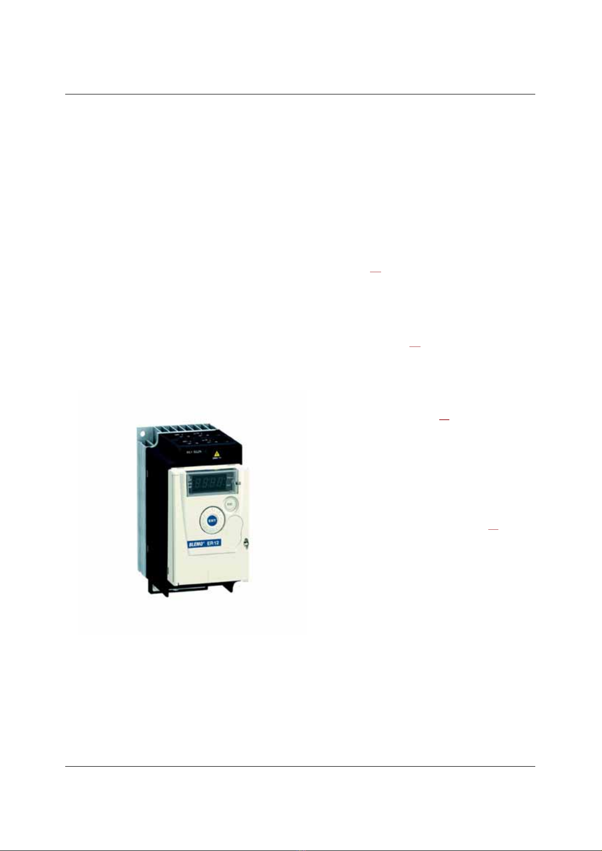
The following ER12 technical documents are available on the BLEMO website (www.blemo.com) as well as on DVD-ROM.
User manual
This manual describes how to install, commission, operate and program the drive.
Simplified manual
This manual is a simplified version of the user manual.
Quick Start
The Quick Start describes how to wire and configure the drive to start motor quickly and simply for simple applications. This document is
delivered with the drive.
Modbus Communication manual
This manual describes the assembly, connection to the bus or network, signaling, diagnostics, and configuration of the communication-
specific parameters via the 7-segment LED display.
It also describes the communication services of the Modbus protocol.
This manual includes all Modbus addresses. It explains the operating mode specific to communication (state chart).
8
Steps for setting up
(also refer to Quick Start)
1. Receive and inspect the drive
• Check that the part number printed on the label is the same as that on the
purchase order.
• Remove the ER12 from its packaging and check that it has not been damaged
in transit.
2. Check the line voltage
• Check that the line voltage is compatible with the voltage
range of the drive (page 10).
3. Mount the drive
• Mount the drive in accordance with the instructions
in this document (page 12).
• Install any options required.
Steps 2to 4must
be performed with
the power off.
4. Wire the drive (page 19)
• Connect the motor, ensuring that its
connections correspond to the voltage.
• Connect the line supply, after making sure
that the power is off.
• Connect the control part.
5. Configure the drive (page 31)
• Apply input power to the drive but
do not give a run command.
• Set the motor parameters
(in Conf mode) only if the factory
configuration of the drive is not
suitable.
• Perform auto-tuning.
6. Start
9
Setup - Preliminary recommendations
Prior to switching on the drive
Prior to configuring the drive
Using the drive with motor having a different size
The motor could have different rating than drive. In case of smaller motor, there is no specific calculation. The motor current has to be set
on Motor thermal current
ItH
parameter page 80. In case of higher size of motor, possible up to 2 sizes (example is using a 4 kW (5.5 HP)
on a 2.2 kW (3 HP) drive) it is necessary to ensure motor current and actual motor power will not pass over nominal power of drive.
Line contactor
Use with a smaller rated motor or without a motor
• In factory settings mode, Output Phase loss
OPL
page 80 is active (
OPL
set to
YES
). To check the drive in a test or maintenance
environment without having to switch to a motor with the same rating as the drive (particularly useful in the case of high power drives),
deactivate Output Phase loss
OPL
(
OPL
set to
nO
).
• Set Motor control type
Ctt
page 55 to
Std
in Motor control menu
drC-
.
DANGER
UNINTENDED EQUIPMENT OPERATION
Ensure that all logic inputs are inactive to help prevent an accidental startup.
Failure to follow these instructions will result in death or serious injury.
DANGER
UNINTENDED EQUIPMENT OPERATION
• Read and understand this manual before installing or operating the ER12 drive.
• Any changes made to the parameter settings must be performed by qualified personnel.
• Ensure that all logic inputs are inactive to help prevent an accidental startup when modifying parameters.
Failure to follow these instructions will result in death or serious injury.
CAUTION
RISK OF DAMAGE TO THE DRIVE
• Avoid operating the contactor frequently to avoid premature aging of the filter capacitors.
• Power cycling must be MORE than 60 seconds.
Failure to follow these instructions can result in equipment damage.
CAUTION
RISK OF DAMAGE TO THE MOTOR
Motor thermal protection will not be provided by the drive if the motor rating current is less than 20% of the rated drive current. Provide
an alternative means of thermal protection.
Failure to follow these instructions can result in equipment damage.
10
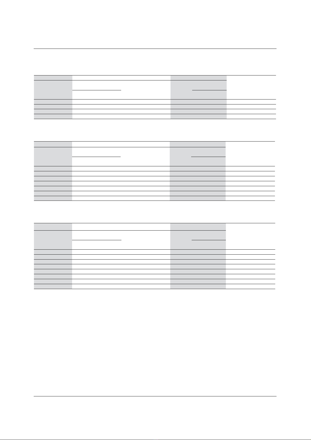
Drive ratings
Single-phase supply voltage: 100…120 V 50/60 Hz
For three Phase Output 200/240 V motors
Single-phase supply voltage: 200…240 V 50/60 Hz
For three Phase Output 200/240 V motors
Three-phase supply voltage: 200…240 V 50/60 Hz
For three Phase Output 200/240 V motors
Motor Line supply (input) Drive (output) Reference
Power indicated
on plate (1)
Maximum line current Apparent
power
Power
dissipated
at nominal
current (1)
Nominal
current
In
Max. transient
current for
at 100 V at 120 V 60 s 2 s
kW HP A A kVA W A A A
0.18 0.25 6 5 1 18 1.4 2.1 2.3 ER12-0.18KU
0.37 0.5 11.4 9.3 1.9 29 2.4 3.6 4 ER12-0.37KU or BU
0.75 1 18.9 15.7 3.3 48 4.2 6.3 6.9 ER12-0.75KU
Motor Line supply (input) Drive (output) Reference
Power indicated
on plate (1)
Maximum line current Apparent
power
Power
dissipated
at nominal
current (1)
Nominal
current
In
Max. transient
current for
at 200 V at 240 V 60 s 2 s
kW HP A A kVA W A A A
0.18 0.25 3.4 2.8 1.2 18 1.4 2.1 2.3 ER12-0.18K
0.37 0.5 5.9 4.9 2 27 2.4 3.6 4 ER12-0.37K or B
0.55 0.75 8 6.7 2.8 34 3.5 5.3 5.8 ER12-0.55K or B
0.75 1 10.2 8.5 3.5 44 4.2 6.3 6.9 ER12-0.75K or B
1.5 2 17.8 14.9 6.2 72 7.5 11.2 12.4 ER12-1.5K or B
2.2 3 24 20.2 8.4 93 10 15 16.5 ER12-2.2K or B
Motor Line supply (input) Drive (output) Reference
Power indicated
on plate (1)
Maximum line current Apparent
power
Power
dissipated
at nominal
current (1)
Nominal
current
In
Max. transient
current for
at 200 V at 240 V 60 s 2 s
kW HP A A kVA W A A A
0.18 0.25 2 1.7 0.7 16 1.4 2.1 2.3 ER12-0.18/3K
0.37 0.5 3.6 3 1.2 24 2.4 3.6 4 ER12-0.37/3K or B
0.75 1 6.3 5.3 2.2 41 4.2 6.3 6.9 ER12-0.75/3K or B
1.5 2 11.1 9.3 3.9 73 7.5 11.2 12.4 ER12-1.5/3K or B
2.2 3 14.9 12.5 5.2 85 10 15 16.5 ER12-2.2/3K or B
3 4 19 15.9 6.6 94 12.2 18.3 20.1 ER12-3.0/3K or B
4 5.5 23.8 19.9 8.3 128 16.7 25 27.6 ER12-4.0/3K or B
(1)These power ratings are for a switching frequency of 4 kHz, in continuous operation. The
switching frequency is adjustable from 2 to 16 kHz.
Above 4 kHz, the drive will reduce the switching frequency if an excessive temperature rise
occurs. The temperature rise is detected by a probe in the power module. Nonetheless,
derating should be applied to the nominal drive current if continuous operation above 4 kHz
is required:
• 10% derating for 8 kHz
• 20% derating for 12 kHz
• 30% derating for 16 kHz
11
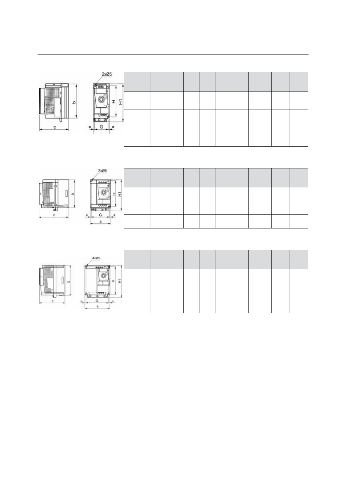
Dimensions and weights
ER12-
a
mm
b
mm
c
mm
(B)
G
mm
H
mm
H1
mm
Ø
mm For
screws
Weight
kg
(lb)
0.18KU
0.18K
0.18/3K
72 142 102.2 60 131 143 2 x 5 M4 0.7
(1.5)
0.37KU/BU
0.37K/B
0.37/3K/B
72 130 121.2
(102.2)
60 120 143 2 x 5 M4 0.8
(1.8)
0.55K/B
0.75K/B
0.75/3K/B
72 130 131.2
(102.2)
60 120 143 2 x 5 M4 0.8
(1.8)
ER12-
a
mm
b
mm
c
mm
(B)
G
mm
H
mm
H1
mm
Ø
mm For
screws
Weight
kg
(lb)
0.75KU
105 130 156.2 93 120 142 2 x 5 M4 1.3
(2.9)
1.5K
2.2K
105 130 156.2 93 120 142 2 x 5 M4 1.4
(3.1)
1.5/3K/B
2.2/3K/B
105 130 131.2
(98.2)
93 120 143 2 x 5 M4 1.2
(2.6)
ER12-
a
mm
b
mm
c
mm
(B)
G
mm
H
mm
H1
mm
Ø
mm For
screws
Weight
kg
(lb)
3.0/3K/B
4.0/3K/B
140 170 141.2
(100.2)
126 159 184 4 x 5 M4 2.0
(4.4)
12
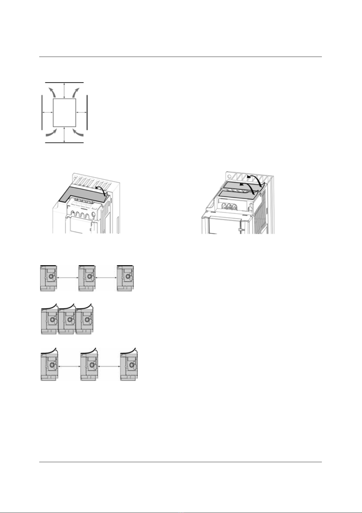
Mounting
Mounting and temperature conditions
Install the unit vertically, at ± 10˚.
Do not place it close to heating elements.
Leave sufficient free space to ensure that the air required for cooling purposes can circulate from the bottom to the
top of the unit.
Free space in front of unit: 10 mm (0.4 in.) minimum.
When IP20 protection is adequate, we recommend that the vent cover(s) on the top of the drive be removed, as
shown below.
We recommend that the drive is installed on a dissipative surface.
Removing the vent cover(s)
Mounting types
≥ 50 mm
(2 in)
≥d ≥d
≥ 50 mm
(2 in)
Type A mounting
Free space ≥50 mm (2 in.) on each side, with vent cover fitted. Mounting type A is
suitable for drive operation at surrounding air temperature less than or equal to 50˚C
(122˚F).
≥ 50 mm
(2 in.)
≥ 50 mm
(2 in.)
Type B mounting
Drives mounted side-by-side, vent cover should be removed (the degree of protection
becomes IP20).
Type C mounting
Free space ≥ 50 mm (2 in.) on each side. Vent cover should be removed for operation at
surrounding air temperature above 50˚C (122˚F). The degree of protection becomes
IP20.
With these types of mounting, the drive can be used up to an ambient temperature of 50˚C (122˚F), with a switching frequency of 4 kHz.
Fanless drives need derating.
≥ 50 mm
(2 in.)
≥ 50 mm
(2 in.)
13
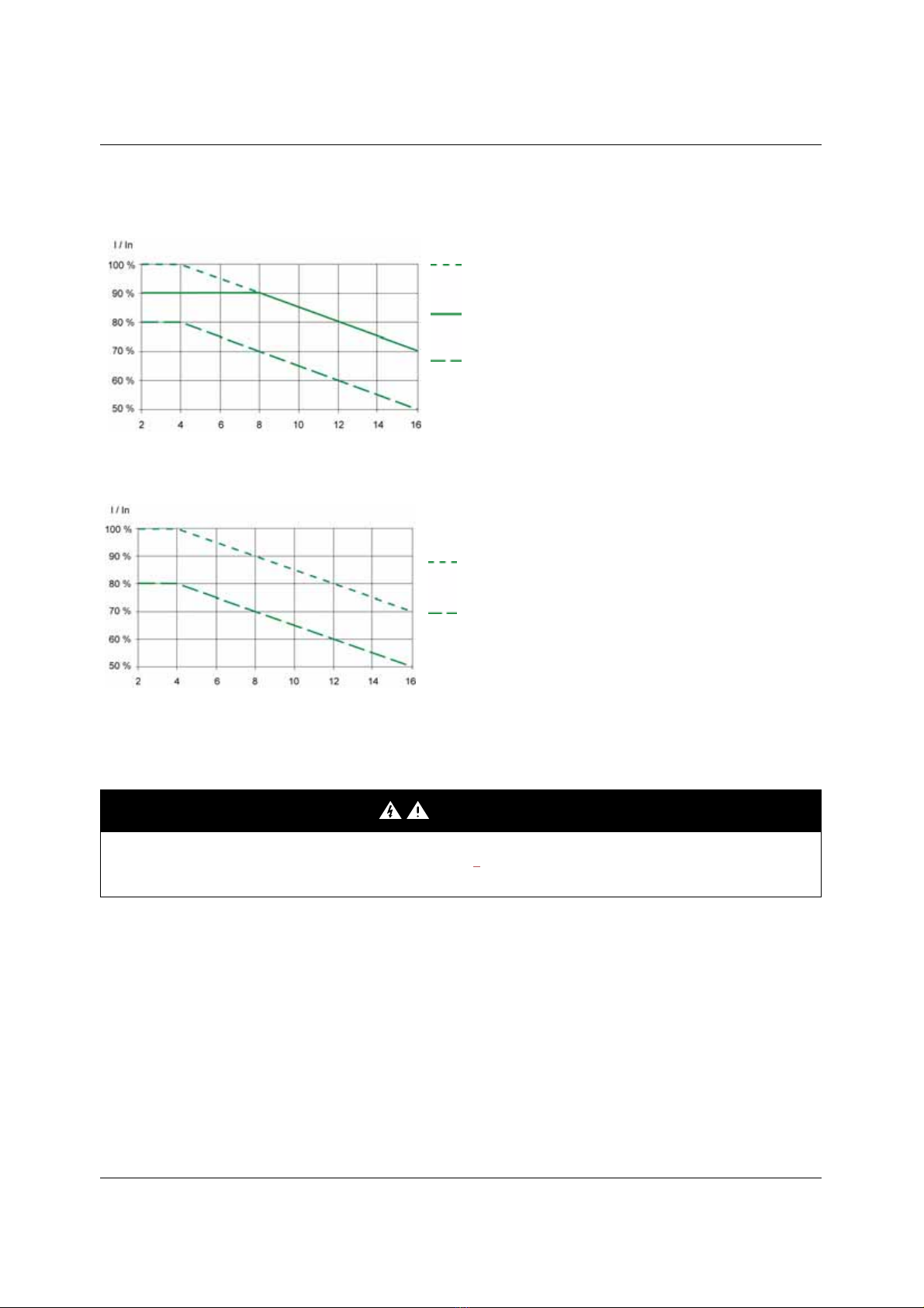
Mounting
Derating curves
Derating curves for the nominal drive current (In) as a function of temperature, switching frequency and mounting type.
ER12-0...K/B, ER12-0.../3K/B, ER12-0.18KU, ER12-0.37KU/BU
For intermediate temperatures (e.g. 55˚C (131˚F)), interpolate between two curves.
Bus voltage measurement procedure
The DC bus voltage can exceed 400 Vdc. Use a properly rated voltage-sensing device when performing this procedure. To measure the
DC bus voltage:
1Disconnect all power.
2Wait 15 minutes to allow the DC bus to discharge.
3Measure the voltage of the DC bus between the PA/+ and PC/– terminals to ensure that the voltage is less than 42 Vdc.
4If the DC bus capacitors do not discharge completely, contact your local BLEMO representative. Do not repair or operate the drive.
DANGER
HAZARD OF ELECTRIC SHOCK, EXPLOSION, OR ARC FLASH
Read and understand the precautions in “Before you begin” on page 5before performing this procedure.
Failure to follow these instructions will result in death or serious injury.
40˚C (104˚F) mounting types A and C
50˚C (122˚F) mounting type C with metal plate
Switching frequency in kHz
40˚C (104˚F) mounting type B
60˚C (140˚F) mounting types A, B and C
Switching frequency in kHz
ER12-1.5K/B, ER12-2.2K/B, ER12-0.75KU, ER12-1.5/3K/B bis ER12-4.0/3K/B
50˚C (122˚F) mounting types A, B and C
60˚C (140˚F) mounting type C with metal plate
14
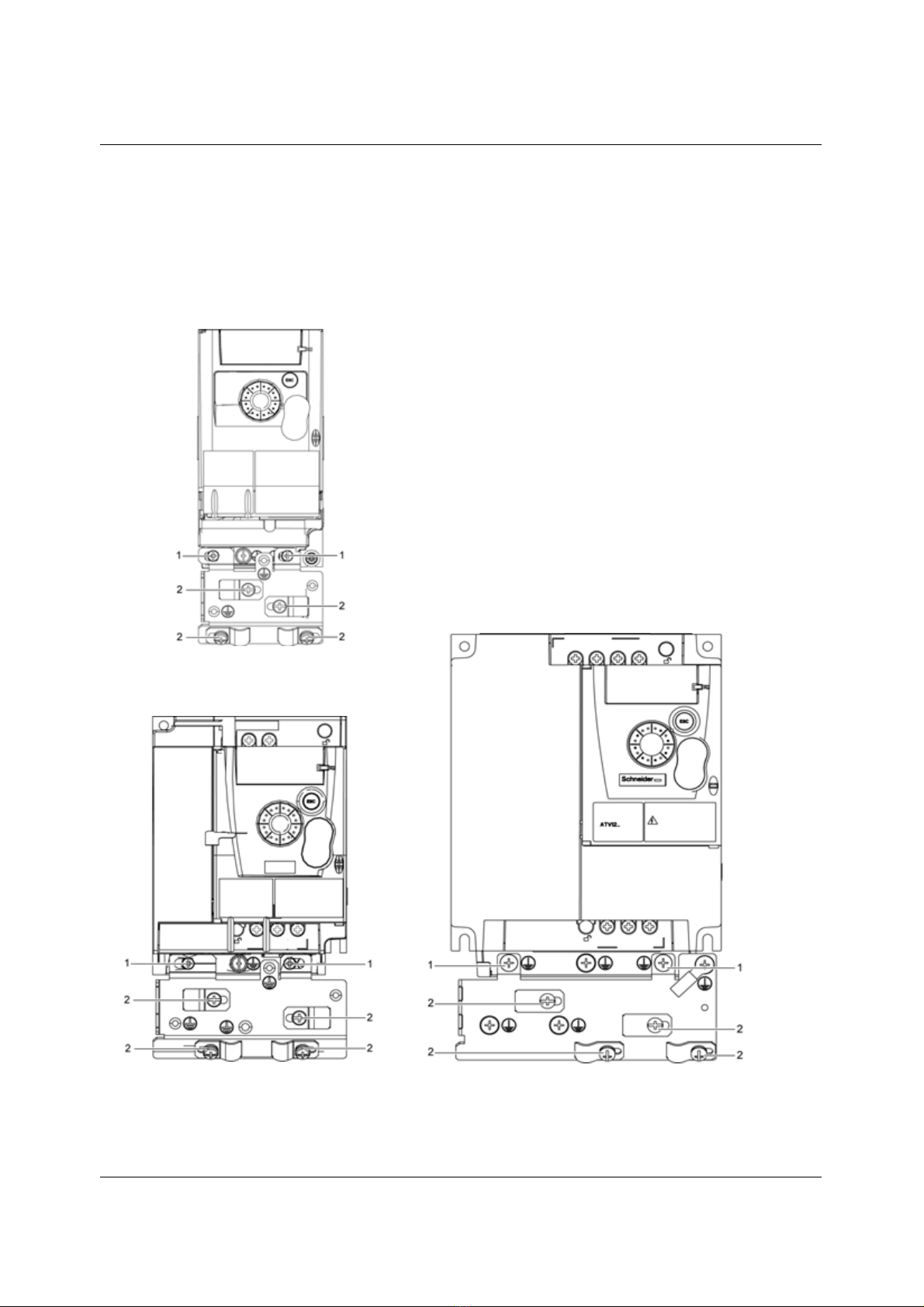
Mounting
Installing the EMC plates
EMC mounting plate: to be ordered separately
Mount the EMC mounting plate to the holes in the ER12 using the 2 screws supplied, as shown in the drawings below.
1. 2 fixing screws
2. 4 x M4 screws for attaching EMC clamps
Size 3:
ER12-3.0/3K/B, ER12-4.0/3K/B
Size 2:
ER12-0.75KU, ER12-1.5K, ER12-2.2K,
ER12-1.5/3K/B, ER12-2.2/3B/B
Size 1:
ER12-0.18KU, ER12-0.18KU/BU, ER12-0.18K,
ER2-0.37K/B to ER12-0.75K/B
ER12-0.18/3K to ER12-0.75/3K/B
ER12-0.37KU/BU
15
Wiring
Recommendations
Keep the power cables separate from control circuits with low-level signals (detectors, PLCs, measuring apparatus, video, telephone).
Always cross control and power cables at 90˚ if possible.
Power and circuit protection
Follow wire size recommendations according to local codes and standards.
Before wiring power terminals, connect the ground terminal to the grounding screws located below the output terminals (see Access to the
motor terminals if you use ring terminals, page 20.
The drive must be grounded in accordance with the applicable safety standards. ER12...K/B drives have an internal EMC filter, and as such
the leakage current is over 3.5 mA.
When upstream protection by means of a "residual current device" is required by the installation standards, a type A circuit breaker should
be used for single-phase drives and type B for 3-phase drives. Choose a suitable model incorporating:
• HF current filtering
• A time delay which prevents tripping caused by the load from stray capacitance on power-up. The time delay is not possible for 30 mA
devices. In this case, choose devices with immunity against accidental tripping, for example RCDs with SI type leakage current
protection.
If the installation includes several drives, provide one "residual current device" per drive.
Control
For control and speed reference circuits, we recommend using shielded twisted cables with a pitch of between 25 and 50 mm (1 and 2 in.),
connecting the shield to ground as outlined on page 25.
Length of motor cables
For motor cable lengths longer than 50 m (164 ft) for shielded cables and longer than 100 m (328 ft) for unshielded cables, please use motor
chokes.
For accessory part numbers, please refer to the catalog.
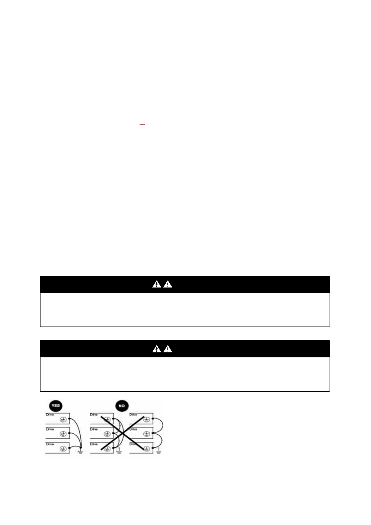
Equipment grounding
Ground the drive according to local and national code requirements. A minimum wire size of 10 mm2(6 AWG) may be required to meet
standards limiting leakage current.
.
DANGER
HAZARD OF ELECTRIC SHOCK, EXPLOSION, OR ARC FLASH
• The drive panel must be properly grounded before power is applied.
• Use the provided ground connecting point as shown in the figure below.
Failure to follow these instructions will result in death or serious injury.
DANGER
ER12-0.75KU, ER12-0.75K/B, ER12-0.75/3K/B - GROUND CONTINUITY HAZARD
An anodized heatsink can create an insulation barrier to the mounting surface. Ensure that you follow the recommended grounding
connections.
Failure to follow these instructions will result in death or serious injury.
• Ensure that the resistance of the ground is one ohm or less.
• When grounding several drives, you must connect each one
directly, as shown in the figure to the left.
• Do not loop the ground cables or connect them in series.
16
Wiring
WARNING
RISK OF DRIVE DESTRUCTION
• The drive will be damaged if input line voltage is applied to the output terminals (U/T1,V/T2,W/T3).
• Check the power connections before energizing the drive.
• If replacing another drive, verify that all wiring connections to the drive comply with wiring instructions in this manual.
Failure to follow these instructions can result in death, serious injury or equipment damage.
WARNING
INADEQUATE OVERCURRENT PROTECTION
• Overcurrent protective devices must be properly coordinated.
• The Canadian Electrical Code and the National Electrical Code require branch circuit protection. Use the fuses recommended in this
manual, page 99.
• Do not connect the drive to a power feeder whose short-circuit capacity exceeds the drive short-circuit current rating listed in this
manual, page 99.
Failure to follow these instructions can result in death, serious injury or equipment damage.

17
Wiring
General wiring diagram
(1) R1 relay contacts, for remote indication of the drive status.
(2) Internal + 24 VDC. If an external source is used (+ 30 VDC maximum), connect the 0 V of the source to the COM terminal, and do not
use the + 24 VDC terminal on the drive.
(3) Reference potentiometer (2.2 kΩ) or similar (10 kΩ maximum).
(4) Optional braking module
(5) Optional braking resistor or other acceptable resistor.
Note:
• Use transient voltage surge suppressors for all inductive circuits near the drive or coupled to the same circuit (relays, contactors,
solenoid valves, etc).
• The ground terminal (green screw) is located on the opposite side in comparison with its position on the ER11 (see wiring trap label).
Single-phase supply 100...120 V
Three-phase supply 200...240 V
ER12-...KU/BU
Single-phase supply 200...240 V
ER12-...K/B
ER12-...3K/B
Source
3-phase
motor
(4)
(5)

18
Wiring
Wiring labels
ER12-...KU/BU
ER12-...K/B
ER12-...3K/B
Input 120 V
Output 240 V
Input 240 V
Output 240 V
Input 240 V
Output 240 V

19
Power terminals
Line supply is at the top of the drive, the motor power supply is at the bottom of the drive. The power terminals can be accessed without
opening the wiring trap if you use stripped wire cables.
Access to the power terminals
Access to the terminals if you use stripped wire cables
Access to the line supply terminals to connect ring terminals
A) IT jumper on ER12-....K/B
B) Grounding screws located below the output terminals.
DANGER
HAZARD OF ELECTRIC SHOCK, EXPLOSION, OR ARC FLASH
Replace the wiring trap before applying power.
Failure to follow these instructions will result in death or serious injury.
CAUTION
RISK OF BODY INJURY
Use pliers to remove snap-off of the wiring trap.
Failure to follow these instructions can result in injury or equipment damage.
Wiring trap
20
Power terminals
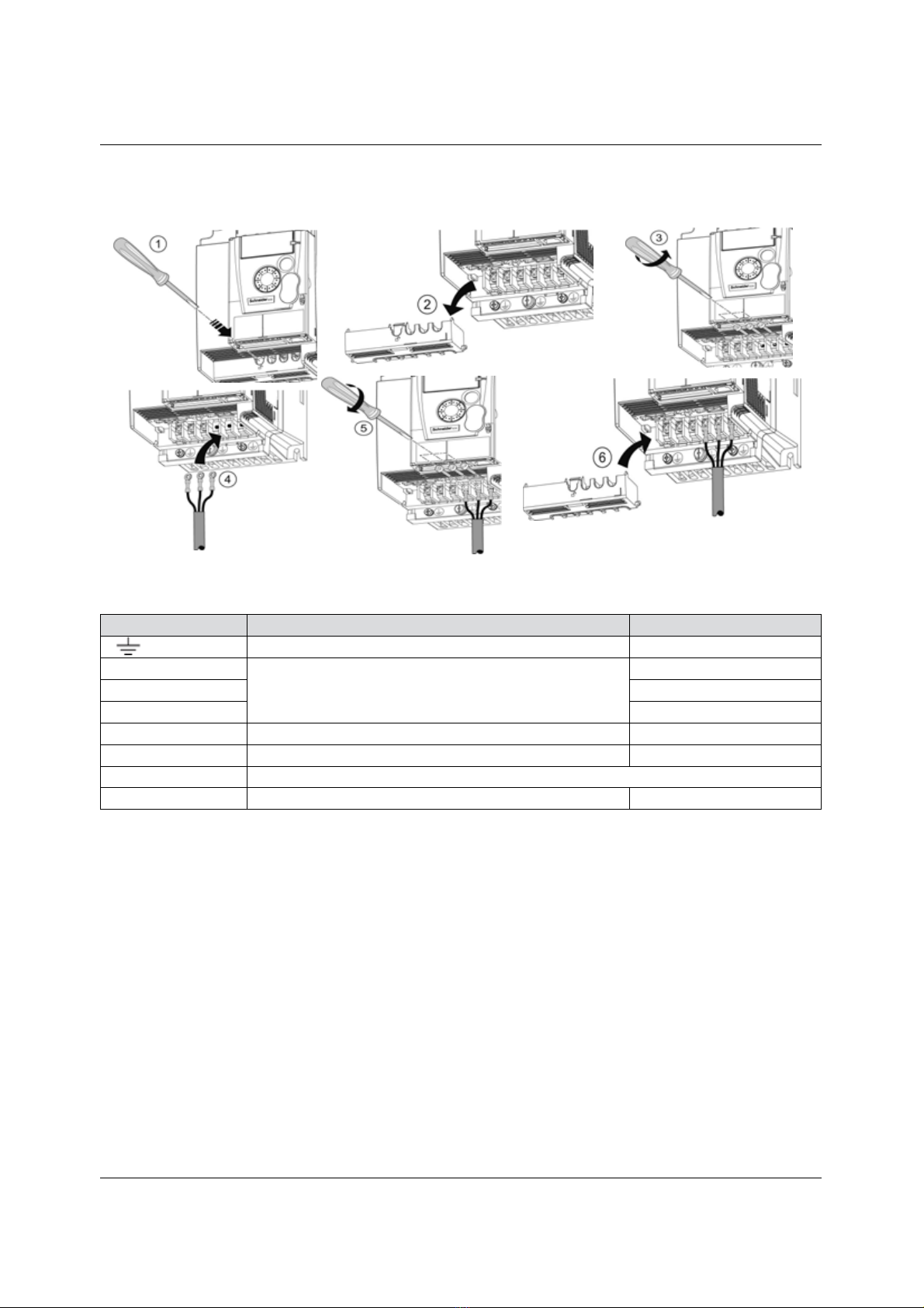
Access to the motor terminals if you use ring terminals
Characteristics and functions of power terminals
Terminal Function For ER12
Ground terminal All ratings
R/L1 - S/L2/N Power supply 1-phase 100…120 V
R/L1 - S/L2/N 1-phase 200…240 V
R/L1 - S/L2 - T/L3 3-phase 200…240 V
PA/+ + output (dc) to the braking module DC Bus (divisible part on wiring trap) All ratings
PC/- – output (dc) to the braking module DC Bus (divisible part on wiring trap) All ratings
PO Not used
U/T1 - V/T2 - W/T3 Outputs to the motor All ratings

21
Power terminals
Arrangement of the power terminals
ER12
Applicable wire
size (1)
Recommended
wire size (2)
Tightening
torque (3)
mm2(AWG) mm2(AWG) N·m (lb.in)
ER12-0.18KU
ER12-0.37KU/BU
ER12-0.18K
to
ER12-0.75K/B
ER12-0.18/3K
to
ER12-0.75/3K/B
2to 3.5
(14 to 12)
2
(14)
0.8 to 1
(7.1 to 8.9)
(1)The value in bold corresponds to the minimum wire gauge to permit secureness.
(2)75˚C (167 ˚F) copper cable (minimum wire size for rated use)
(3)Recommended to maximum value.
ER12
Applicable
wire size (1)
Recommended
wire size (2)
Tightening
torque (3)
mm2(AWG) mm2(AWG) N·m (lb.in)
ER12-0.75KU
ER12-1.5K
ER12-2.2K
3.5 to 5.5
(12 to 10)
5.5
(10) 1.2 to 1.4
(10.6 to 12.4)
ER12-1.5/3K/B
ER12-2.2/3K/B
2to 5.5
(14 to 10)
2 (14)
3.5 (12)
ER12
Applicable
wire size (1)
Recommended
wire size (2)
Tightening
torque (3)
mm2(AWG) mm2(AWG) N·m (lb.in)
ER12-3.0/3K/B
ER12-4.0/3K/B 5.5 (10) 5.5 (10) 1.2 to 1.4
(10.6 to 12.4)
Table of contents
Other BLEMO Inverter manuals


Popular Inverter manuals by other brands

Sunways
Sunways NT 2600 user manual

IRIS
IRIS QuietPower 1800 Operator's manual

Dass
Dass DSP-123K5-OD Operation and installation manual

Zgonc
Zgonc yellow PROFILINE YPL 6000-D Translation of original instruction manual

Turbo Energy
Turbo Energy Hybrid Series instruction manual

Salicru
Salicru CV50-008-4F user manual


SunSynk
SunSynk SUNSYNK-8K-SG01LP1 Installer manual

Asterion
Asterion HYBRID 30K user manual

Sinclair
Sinclair SDV5 Series User & installation manual

Schumacher Electric
Schumacher Electric PID-410 owner's manual

Ginlong
Ginlong Solis-100K-5G Installation and operation manual

BOSSCO
BOSSCO MIG 200 operating manual