BLEMO ER23K Owner's manual
Installation
manual
ER2
3
K
Inverter
EN 61800-3
Line voltage:
1 ~
200
-
240 V
-
Output
: 3~ 0
-
240 V Power
: 0,18
-
2,2
kW
Line voltage: 1(3)~
200
- 240 V - Output: 3~ 0
- 240 V Power: 0,18-
15,0
kW
Line voltage
3 ~
380
-
500 V
-
Output:
3~ 0
-
500 V
Power:
0,
37
-
15,0
kW
Line voltage 3 ~
525
- 600 V - Output: 3~ 0
- 600 V Power: 0,75-
15,0
kW
COMPACT-LINE
02/2010
Programming manual ER23K


3
Contents
Important information __________________________________________________________________________________________ 4
Before you begin______________________________________________________________________________________________ 5
Documentation structure________________________________________________________________________________________ 7
Steps for setting up the drive ____________________________________________________________________________________ 8
Setup - Preliminary Recommendations ____________________________________________________________________________ 9
Factory configuration _________________________________________________________________________________________ 10
Basic functions ______________________________________________________________________________________________ 11
Remote display terminal option, ER22 ____________________________________________________________________________ 13
Remote graphic display terminal option, ER40______________________________________________________________________ 14
Remote display terminal option, ER12 ____________________________________________________________________________ 18
Structure of the parameter tables________________________________________________________________________________ 19
Compatibility of functions ______________________________________________________________________________________ 20
List of functions that can be assigned to inputs/outputs_______________________________________________________________ 22
List of functions that can be assigned to the Network and Modbus control word bits ________________________________________ 24
Checklist___________________________________________________________________________________________________ 25
Programming _______________________________________________________________________________________________ 26
[SPEED REFERENCE] (rEF-) menu _____________________________________________________________________________ 30
[SETTINGS] (SEt-) menu ______________________________________________________________________________________ 31
[MOTOR CONTROL] (drC-) menu _______________________________________________________________________________ 39
[INPUTS / OUTPUTS CFG] (I-O-) menu __________________________________________________________________________ 45
[COMMAND] (CtL-) menu______________________________________________________________________________________ 48
[COMMAND] (CtL-) menu______________________________________________________________________________________ 59
[APPLICATION FUNCT.] menu (FUn-) ___________________________________________________________________________ 60
[FAULT MANAGEMENT] (FLt-) menu ____________________________________________________________________________ 86
[COMMUNICATION] (COM-) menu ______________________________________________________________________________ 92
[MONITORING] (SUP-) menu __________________________________________________________________________________ 94
Migration ER22K/P - ER23K____________________________________________________________________________________ 99
Diagnostics and troubleshooting________________________________________________________________________________ 100
Index of functions ___________________________________________________________________________________________ 105
Index of parameter codes and customer settings___________________________________________________________________ 106
Wiring / evaluation of PTC ___________________________________________________________________________________ 120

4
Important information
NOTICE
Read these instructions carefully, and look at the equipment to become familiar with the device before trying to install, operate, or maintain
it. The following special messages may appear throughout this documentation or on the equipment to warn of potential hazards or to call
attention to information that clarifies or simplifies a procedure.
PLEASE NOTE
The word "drive" as used in this manual refers to the "controller portion" of the adjustable speed drive as defined by NEC.
Electrical equipment should be installed, operated, serviced, and maintained only by qualified personnel. No responsibility is assumed by
BLEMO for any consequences arising out of the use of this documentation.
© 2009 BLEMO. All rights reserved.
DANGER
DANGER indicates an imminently hazardous situation which, if not avoided, will result in death, serious injury or
equipment damage.
WARNING
WARNING indicates a potentially hazardous situation which, if not avoided, can result in death, serious injury or
equipment damage.
CAUTION
CAUTION indicates a potentially hazardous situation which, if not avoided, can result in injury or equipment damage.
CAUTION
CAUTION, used without the safety alert symbol, indicates a potentially hazardous situation which, if not avoided, can
result in equipment damage.
The addition of this symbol to a Danger or Warning safety label indicates that an electrical hazard exists, which will result in
personal injury if the instructions are not followed.
This is the safety alert symbol. It is used to alert you to potential personal injury hazards. Obey all safety messages that follow
this symbol to avoid possible injury or death.

5
Before you begin
Read and understand these instructions before performing any procedure with this drive.
DANGER
HAZARD OF ELECTRIC SHOCK, EXPLOSION, OR ARC FLASH
• Read and understand this manual before installing or operating the ER23K drive. Installation, adjustment, repair, and maintenance
must be performed by qualified personnel.
• The user is responsible for compliance with all international and national electrical code requirements with respect to grounding of
all equipment.
• Many parts of this drive, including the printed circuit boards, operate at the line voltage. DO NOT TOUCH. Use only electrically
insulated tools.
• DO NOT touch unshielded components or terminal strip screw connections with voltage present.
• DO NOT short across terminals PA/+ and PC/– or across the DC bus capacitors.
• Before repairing the variable speed drive:
- Disconnect all power, including external control power that may be present.
- Place a “DO NOT TURN ON” label on all power disconnects.
- Lock all power disconnects in the open position.
- WAIT 15 MINUTES to allow the DC bus capacitors to discharge.
- Measure the voltage of the DC bus between the PA/+ and PC/– terminals to ensure that the voltage is less than 42 Vdc.
- If the DC bus capacitors do not discharge completely, contact your local BLEMO representative. Do not repair or operate
the drive
• Install and close all covers before applying power or starting and stopping the drive.
Failure to follow these instructions will result in death or serious injury.
DANGER
UNINTENDED EQUIPMENT OPERATION
• Read and understand this manual before installing or operating the ER23K drive.
• Any changes made to the parameter settings must be performed by qualified personnel.
Failure to follow these instructions will result in death or serious injury.
WARNING
DAMAGED EQUIPMENT
Do not install or operate any drive that appears damaged.
Failure to follow these instructions can result in death, serious injury, or equipment damage.

6
Before you begin
a) For additional information, refer to NEMA ICS 1.1 (latest edition), "Safety Guidelines for the Application, Installation, and Maintenance of
Solid State Control" and to NEMA ICS 7.1 (latest edition), "Safety Standards for Construction and Guide for Selection, Installation and
Operation of Adjustable-Speed Drive Systems".
WARNING
LOSS OF CONTROL
• The designer of any wiring diagram must take account of potential control channel failure modes and, for certain critical control
functions, incorporate a way of achieving a safe state during and after a channel failure. Examples of critical control functions are
emergency stop and overtravel stop.
• Separate or redundant control channels must be provided for critical control functions.
• System control paths may include communication links. Consideration must be given to the implications of unanticipated transmission
delays or failures of the link.
a
Failure to follow these instructions can result in death, serious injury, or equipment damage.

7
Documentation structure
The following ER23K technical documents are available on the BLEMO website (www.blemo.com).
Installation Manual
This manual describes how to install and connect the drive.
User manual
This manual describes the functions and parameters of the drive's terminals and how to use them.
Simplified manual
This manual is a simplified version of the installation and programming manuals. It is supplied with the drive.
Quick Start
This document describes how to connect and configure the drive so that the motor can be started both quickly and easily for basic
applications. This document is supplied with the drive.
Manuals for Modbus, CANopen, etc.
These manuals describe the installation process, the bus or network connections, signaling, diagnostics and the configuration of parameters
specific to communication.
They also describe the communication services of the protocols.

8
Steps for setting up the drive
3. Configure:
•
The nominal frequency of the motor
[Standard mot. freq] (bFr) page 39 if this is
not 50 Hz,
•
The motor parameters in the [MOTOR
CONTROL] (drC-) menu, page 39, only if
the factory configuration of the drive is
not suitable,
•
The application functions in the
[INPUTS / OUTPUTS CFG] (I-O-) menu,
page 45, the [COMMAND] (CtL-) menu,
page 48, and the [APPLICATION
FUNCT.] (FUn-) menu, page 60, only if
the factory configuration of the drive
is not suitable.
4. In the [SETTINGS] (SEt-) menu,
adjust the following
parameters:
•
[Acceleration] (ACC), page 31 and
[Deceleration], (dEC) page 31,
•
[Low speed] (LSP), page 32 and [High
speed] (HSP), page 32,
•
[Mot. therm. current] (ItH), page 32.
2. Apply input power to the drive, but do not
give a run command.
Tips:
•
Before beginning programming, complete the customer
setting tables, page
106
.
•
Use the
[Restore config.] (FCS) parameter, page 44
,
to return to the factory settings at any time.
• To locate the description of a function quickly, use the index
of functions on page
105
.
• Before configuring a function, read carefully the "Function
compatibility" section on pages
20
and
21
.
•Note:
The following operations must be performed for optimum
drive performance in terms of accuracy and response time:
-
Enter the values indicated on the (motor) rating plate in
the
[MOTOR CONTROL] (drC-)
menu, page
39
.
-
Perform auto-tuning with the motor cold and connected
using the
[Auto-tuning] (tun)
parameter, page
41
.
-
Adjust the
[FreqLoopGain] (FLG)
parameter, page
32
and the
[Fr.Loop.Stab] (StA)
parameter, page
33
.
INSTALLATION
1.
Please refer to the Installation Manual.
PROGRAMMING
5. Start the drive.

9
Setup - Preliminary Recommendations
Before powering up the drive
Before configuring the drive
Start-up
Note: When factory settings apply and during power-up/manual reset or after a stop command, the motor can only be powered once the
"forward", "reverse" and "DC injection stop" commands have been reset. If they have not been reset, the drive will display [Freewheel stop]
(nSt) but will not start. If the automatic restart function has been configured ([Automatic restart] (Atr) parameter in the [FAULT
MANAGEMENT] (FLt-) menu, page 86), these commands are taken into account without a reset (to zero) being necessary.
Line contactor
Using a motor with a lower rating or dispensing with a motor altogether
• With the factory settings, motor output phase loss detection is active ([Output Phase Loss] (OPL) = [YES] (YES), page 89). To avoid
having to use a motor with the same rating as the drive when testing the drive or during a maintenance phase, deactivate motor output
phase loss detection ([Output Phase Loss] (OPL) = [No] (nO)). This can prove particularly useful if very powerful drives are being
used.
• Set the [U/F mot 1 selected] (UFt) parameter, page 42, on [Cst. torque] (L) in the [MOTOR CONTROL] (drC-) menu.
DANGER
UNINTENDED EQUIPMENT OPERATION
Make sure that all logic inputs are inactive to avoid any unintended operation.
Failure to follow these instructions will result in death or serious injury.
DANGER
UNINTENDED EQUIPMENT OPERATION
• Read and understand this manual before installing or operating the ER23K drive.
• Any changes made to the parameter settings must be performed by qualified personnel.
• Make sure that all logic inputs are inactive to avoid any unintended operation when parameters are being changed.
Failure to follow these instructions will result in death or serious injury.
CAUTION
RISK OF DAMAGE TO DRIVE
• Frequent use of the contactor will cause premature ageing of the filter capacitors.
• Do not have cycle times less than 60 seconds.
Failure to follow these instructions can result in equipment damage.
CAUTION
RISK OF DAMAGE TO MOTOR
Motor thermal protection will not be provided by the drive if the motor 's nominal current is 20% lower than that of the drive. Find an
alternative source of thermal protection.
Failure to follow these instructions can result in equipment damage.

10
Factory configuration
Factory settings
The ER23K is factory-set for the most common operating conditions:
• Display: drive ready [Ready] (rdY) with motor stopped, and motor frequency with motor running.
• The LI5 and LI6 and logic inputs, AI3 analog input, AOC analog output, and R2 relay are unaffected.
• Stop mode when fault detected: freewheel
Check whether the values above are compatible with the application. If necessary, the drive can be used without changing the settings.
(1)If you want to keep the drive's presettings to a minimum, select the macro configuration [Macro configuration] (CFG) = [Start/stop] (StS)
followed by [Restore config.] (FCS) = [Config. CFG] (InI) (page 44).
The [Start/stop] (StS) macro configuration is the same as the factory configuration, apart from the I/O assignment:
• Logic inputs:
- LI1, LI2 (reversing): 2-wire transition detection control, LI1 = run forward, LI2 = run reverse.
- LI3 to LI6: Inactive (not assigned).
• Analog inputs:
- AI1: Speed reference 0-10 V.
- AI2, AI3: Inactive (not assigned).
• Relay R1: The contact opens in the event of a detected fault (or drive off).
• Relay R2: Inactive (not assigned).
• Analog output AOC: 0-20 mA, inactive (not assigned).
Code Description Value Page
bFr [Standard mot. freq] [50Hz IEC] 39
tCC [2/3 wire control] [2 wire] (2C): 2-wire control 29
UFt [U/F mot 1 selected] [SVC] (n): Sensorless flux vector control for constant torque applications 42
ACC
DEC [Acceleration]
[Deceleration] 3.00 seconds 61
LSP [Low speed] 0 Hz 32
HSP [High speed] 50 Hz 32
ItH [Mot. therm. current] Nominal motor current (value depending on drive rating) 32
SdC1 [Auto DC inj. level 1] 0.7 x nominal drive current, for 0.5 seconds 33
SFr [Switching freq.] 4 kHz 38
rrS [Reverse assign.] [LI2] (LI2): Logic input LI2 46
PS2 [2 preset speeds] [LI3] (LI3): Logic input LI3 69
PS4 [4 preset speeds] [LI4] (LI4): Logic input LI4 69
Fr1 [Ref.1 channel] [AI1] (AI1) - Analog input AI1 28
SA2 [Summing ref. 2] [AI2] (AI2) - Analog input AI2 67
r1 [R1 Assignment] [No drive flt] (FLt): The contact opens when a fault is detected or when the drive has
been switched off 47
brA [Dec ramp adapt.] [Yes] (YES): Function active (automatic adaptation of deceleration ramp) 62
Atr [Automatic restart] [No] (nO): Function inactive 86
Stt [Type of stop] [Ramp stop] (rMP): On ramp 63
CFG [Macro configuration] [Factory set.] (Std) (1) 43

11
Basic functions
Drive thermal protection
Functions:
Thermal protection by PTC probe fitted on the heatsink or integrated in the power module.
Indirect protection of the drive against overloads by tripping in the event of an overcurrent. Typical tripping values:
- Motor current = 185% of nominal drive current: 2 seconds
- Motor current = 150% of nominal drive current: 60 seconds
Drive ventilation
The fan starts up when the drive is powered up then shuts down after 10 seconds if a run command has not been received.
The fan is powered automatically when the drive is unlocked (direction of operation + reference). It is powered down a few seconds after
the drive is locked (motor speed < 0.2 Hz and injection braking completed).
Time
(seconds)
Motor current/In drive
12
Basic functions
Motor thermal protection
Function:
Thermal protection by calculating the I
2
t.
The protection takes account of self-cooled motors.
CAUTION
RISK OF DAMAGE TO MOTOR
External protection against overloads is required under the following circumstances:
• When the product is being switched on again, as there is no memory to record the motor thermal state
• When supplying more than one motor
• When supplying motors with ratings less than 0.2 times the nominal drive current
• When using motor switching
Failure to follow these instructions can result in equipment damage.
Tripping time t
in seconds
Motor current/
[Mot. therm. current] (ItH)

13
Remote display terminal option, ER23K
This terminal is a local control unit which can be mounted on the door of the wall-mounted or floor-standing enclosure. It has a cable with
connectors, which is connected to the drive serial link (see the manual supplied with the terminal). Its display capabilities are practically
identical to those of the ER23K. With this terminal, however, up and down arrows are used for navigation rather than a jog dial. There is
also an access locking switch for the menus. There are three buttons for controlling the drive (1):
• FWD/REV: Reversal of the direction of rotation
• RUN: Motor run command
• STOP/RESET: Motor stop command or reset
Pressing the button a first time stops the motor, and if DC injection standstill braking is configured, pressing it a second time stops this
braking.
View of the front panel:: View of the rear panel :
Note: Protection via customer confidential code has priority over the switch.
Note:
• The remote terminal access locking switch also locks access by the drive keys.
• When the remote display terminal is disconnected, any locking remains active for the drive keys.
• The remote display terminal will only be active if the [Modbus baud rate] (tbr) parameter in the [COMMUNICATION] (COM-) menu,
page 92, still has its factory setting: [19.2 Kbps] (19.2).
(1)To activate the buttons on the remote display terminal, you first have to configure [HMI command] (LCC) = [Yes] (YES), page 58.
Saving and loading configurations
Up to four complete configurations for ER23K drives without an option card can be stored on the remote display terminal. These
configurations can be saved, transported and transferred from one drive to another of the same rating. 4 different operations for the same
device can also be stored on the terminal.
See the [Saving config.] (SCS) and [Restore config.] (FCS) parameters in the [MOTOR CONTROL] (drC-) menu, pages 43 and 44, the
[INPUTS / OUTPUTS CFG] (I-O-) menu, pages 47 and 47, the [COMMAND] (CtL-) menu, pages 59 and 59, and the [APPLICATION
FUNCT.] (FUn-) menu, pages 85 and 85.
To transfer a configuration between an ER23K and an ER22, follow the procedure on page 85.
4-character
display
Connector
Access locking switch:
• Position: [MONITORING] (SUP-) and [SPEED
REFERENCE] (rEF-) menus can be
accessed.
[SETTINGS] (SEt-), [MONITORING]
(SUP-) and [SPEED REFERENCE]
(rEF-) can be accessed.
• Position:
• Position: All menus can be accessed

14
Remote graphic display terminal option, ER40
Description of the terminal
Thanks to the screen size of this graphic display terminal, which works with FLASH V1.1IE19 or higher and is part of the ER40, it is possible
to display more detailed information than can be shown on an on-board display. It is connected in the same way as the ER23K remote
display terminal.
Note: Keys 3, 4, 5and 6can be used to control the drive directly, if control via the terminal is activated.
To activate the buttons on the remote display terminal, you first have to configure [HMI command] (LCC) = [Yes] (YES), page 58.
1 Graphic display
2 Function keys:
F1: CODE
F2, F3: not used
F4: MODE
3 Button to stop/reset
4 Run button
5 Navigation button:
• Press (ENT): - To save the current value
- To enter the selected menu or parameter
• Turn CW/CCW: - To increase or decrease a value
- To go to the next or previous line
- To increase or decrease the reference if control via
the display terminal is activated
7
ESC button:cancels a value, a
parameter or a menu to return
to the previous selection
6
Button forreversingthedirection
of rotation of the motor
15
Remote graphic display terminal option, ER40 (continued)
Powering up the graphic display terminal for the first time
When powering up the graphic display terminal for the first time, the user has to select the required language.
Display after the graphic display terminal has been
powered up for the first time.
Select the language and press ENT.
The drive's rating details will now appear.
The [MAIN MENU]
follows automatically.
3 seconds
or ENT
Automatically switches to the [DRIVE MENU]
menu after 3 seconds.
Select the menu and press ENT.
LANGUAGE
English
Français
Deutsch
Espanol
Italiano
Chinese
Russian
Turkish
ER23K
1.5kW/2HP 200/240V
MAIN MENU
DRIVE MENU
LANGUAGE
DRIVE MENU
SPEED REFERENCE
SETTINGS
MOTOR CONTROL
INPUTS / OUTPUTS CFG
COMMAND
Code Mode
APPLICATION FUNCT.
FAULT MANAGEMENT
COMMUNICATION

16
Remote graphic display terminal option, ER40 (continued)
Powering up the drive for the first time
When powering up the drive for the first time, the user immediately accesses the 3 parameters below: [Standard mot. freq] (bFr), [Ref.1
channel] (Fr1), and [2/3 wire control] (tCC), page 29. .
Display after the drive has been powered up for the
first time.
The [MAIN MENU]
follows automatically.
3 seconds
Automatically switches to the [DRIVE MENU]
menu after 3 seconds.
Select the menu and press ENT.
ESC
The word "Ready" appears on the graphic display
terminal if you press the ESC key when in the
[DRIVE MENU].
ER23K
1.5kW/2HP 200/240V
MAIN MENU
DRIVE MENU
LANGUAGE
DRIVE MENU
Standard mot. freq
2/3 wire control
Ref.1 channel
SPEED REFERENCE
SETTINGS
MOTOR CONTROL
INPUTS / OUTPUTS CFG
COMMAND
APPLICATION FUNCT.
FAULT MANAGEMENT
COMMUNICATION
DRIVE MENU
Ready
Code Mode

17
Remote graphic display terminal option, ER40 (continued)
Subsequent power-ups
Display after powering up.
The [MAIN MENU]
follows automatically.
3 seconds
Automatically switches to the [DRIVE MENU]
menu after 3 seconds.
Select the menu and press ENT.
ESC
The word "Ready" appears on the graphic display
terminal if you press the ESC key when in the
[DRIVE MENU].
ER23K
1.5kW/2HP 200/240V
MAIN MENU
DRIVE MENU
LANGUAGE
DRIVE MENU
SPEED REFERENCE
SETTINGS
MOTOR CONTROL
INPUTS / OUTPUTS CFG
COMMAND
Code Mode
APPLICATION FUNCT.
FAULT MANAGEMENT
COMMUNICATION
DRIVE MENU
Ready
Code Mode

18
Remote display terminal option, ER12
Description of the terminal
This terminal is a local control unit which can be mounted on the door of the wall-mounted or floor-standing enclosure. It has a cable with
connectors, which is connected to the drive serial link (see the manual supplied with the terminal). Its display capabilities are practically
identical to those of the ER23. With this terminal, up and down arrows are used for navigation rather than a jog dial.
(1) If the drive is locked by a code ([PIN code 1] (COd), page 97), pressing the Mode key enables you to switch from the [MONITORING]
(SUP-) menu to the [SPEED REFERENCE] (rEF-) menu and vice versa.
To activate the buttons on the remote display terminal, you first have to configure [HMI command] (LCC) = [Yes] (YES), page 58.
1 Graphic display
2 MODE button (1): If [SPEED
REFERENCE] (rEF-) is displayed,
this will take you to the
[SETTINGS] (SEt-) menu. If not, it
will take you to the [SPEED
REFERENCE] (rEF-) menu.
3 ESC button
Used to quit a menu/parameter or
remove the currently displayed
value in order to revert
to the previous value
retained in the memory
4 RUN button
Executes the function
assuming it has been
configured
5 Navigation keys
6 ENT button
Used to save the current value or
access the selected menu/parameter
8 Button for reversing the direction
of rotation of the motor
7 STOP button
Used to stop the motor and
perform a reset
19
Structure of the parameter tables
The parameter tables contained in the descriptions of the various menus are organized as follows.
Example :
APPLICATION FUNCT.] menu (Fun-)
Code Name/Description Adjustment
range Factory
setting
PI-
•
[PI regulator]
Note: The "PI regulator" function is incompatible with several functions (see page 20). It can only
be configured if these functions are unassigned, in particular the summing inputs (set [Summing
ref. 2] (SA2) to [No] (nO), page 67) and the preset speeds (set [2 preset speeds] (PS2) and
[4 preset speeds] (PS4) to [No] (nO), page 69) which will have been assigned as part of the
factory settings.
PIF
• [PID feedback ass.]
[Non] (nO)
no
AI1
A12
A13
-
[Non] (nO): not assigned
-
[AI1] (AI1): analog input AI1
-
[AI2] (AI2): analog input AI2
-
[AI3] (AI3): analog input AI3
5
2
3
1
4
6
8
7
1. Name of menu on 4-digit 7-segment display
2. Submenu code on 4-digit 7-segment display
3. Parameter code on 4-digit 7-segment display
4. Parameter value on 4-digit 7-segment display
5. Name of menu on ER40 graphic display terminal
6. Name of submenu on ER40 graphic display terminal
7. Name of parameter on ER40 graphic display terminal
8. Value of parameter on ER40 graphic display terminal
20
Compatibility of functions
Incompatible functions
The following functions will be inaccessible or deactivated in the cases described below:
Automatic restart
This is only possible for the 2-wire level control type ([2/3 wire control] (tCC) = [2 wire] (2C) and [2 wire type] (tCt) = [Level] (LEL) or
[Fwd priority] (PFO)).
Catch on the fly
This is only possible for the 2-wire level control type ([2/3 wire control] (tCC) = [2 wire] (2C) and [2 wire type] (tCt) = [Level] (LEL) or
[Fwd priority] (PFO)).
This function is locked if automatic standstill injection has been configured as DC ([Auto DC injection] (AdC) = [Continuous] (Ct)).
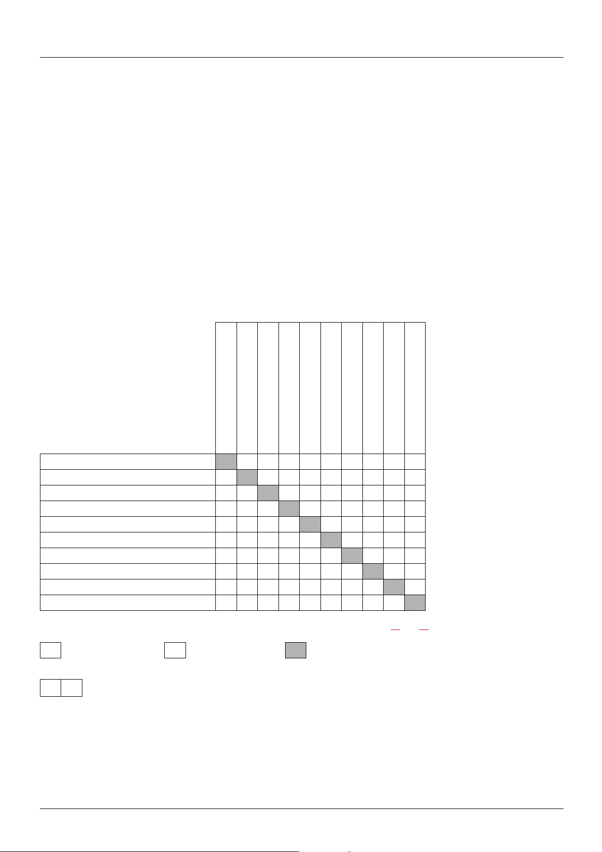
Function compatibility table
The choice of application functions may be limited by the number of I/O and by the fact that some functions are incompatible with one
another. Functions which are not listed in this table are compatible.
If there is an incompatibility between functions, the first function configured will prevent the others being configured.
To configure a function, first check that functions which are incompatible with it are unassigned, especially those which are
assigned in the factory settings.
(1)Excluding special application with reference channel [Ref.2 channel] (Fr2) (see diagrams 51 and 53)
Priority functions (functions which cannot be active at the same time):
Stop functions take priority over run commands.
Speed references via logic command take priority over analog references.
Summing inputs (factory setting)
+/- speed (1)
Management of limit switches
Preset speeds (factory setting)
PI regulator
Jog operation
Brake control
DC injection stop
Fast stop
Freewheel stop
Summing inputs (factory setting)
+/- speed (1)
Management of limit switches
Preset speeds (factory setting)
f
PI regulator
Jog operation
f
f
Brake control
DC injection stop
Fast stop
Freewheel stop
f f
Incompatible functions Compatible functions Not applicable
f
The function marked with the arrow takes priority over the other.
This manual suits for next models
1
Table of contents
Other BLEMO Inverter manuals


Popular Inverter manuals by other brands


BARRON
BARRON EXITRONIX Tucson Micro Series installation instructions

Baumer
Baumer HUBNER TDP 0,2 Series Mounting and operating instructions

electroil
electroil ITTPD11W-RS-BC Operation and Maintenance Handbook

Silicon Solar
Silicon Solar TPS555-1230 instruction manual

Mission Critical
Mission Critical Xantrex Freedom SW-RVC owner's guide

HP
HP 3312A Operating and service manual


