Dass DSP-123K5-OD Specification sheet

DASS Tech
Photovoltaic Grid-Connected Inverter
DSP-123K5-OD ver1.0
Operation and Installation Manual

1
NOTICE
1. Caution for safety.................................................................2
2. Product ...........................................................................5
2.1 General .....................................................................5
2.2 Specification................................................................8
3. Installation.......................................................................9
3.1 Configuration................................................................9
3.2 Installation place...........................................................9
3.3 Terminal connection diagram.................................................10
3.4 Wiring......................................................................11
3.5 Cautions for mounting the inverter to the wall ................................14
4. Operation.........................................................................15
4.1 Display.....................................................................15
4.2 Basic mode .................................................................15
4.3 Operation method............................................................17
5. Function..........................................................................17
5.1 Descriptions................................................................17
6. Maintenance & repair..............................................................19
6.1 Types of error .............................................................19
6.2 Customer service............................................................20
7. Quality assurance.................................................................21
7.1 Warranty letter.............................................................21

2
1. Cautions for safety
Cautions for safety must be kept under any circumstances in order to prevent accident or dangers for safe and
right use.
There are two types of caution in the manual, warning and attention, as below.
Warning
Attention
Symbols in the products and the operation and installation manual indicate as follows.
Indicates that you must be careful for possible danger under certain conditions
Indicates that you must be careful for electric shock under certain conditions.
After reading this operation and installation manual, keep the manual in place that anyone can read it anytime.
Read this operation and installation manual carefully in order to use the functions of DSP series sufficiently and
safely.
Warning
Do not operate when the cover is open.
It could cause electric shock as high voltage terminal or electric charging is exposed outside.
Do not adjust switch when your hands are wet.
It could cause electric shock.
Do not open cover when power is on or in operation.
It could cause electric shock.
Do not open cover even when the power is off except for regular check.
The inverter is still charged even if the power is off due to the long-time charging, which could cause electric
shock.
Shut off the power and wait more than 10 minutes to confirm complete discharging to VOM from
inverter when doing wiring work or regular check.
It could cause electric shock.
Do not use this inverter in the event of damaged wire.
It could cause electric shock.
Do not put any heavy items on the wire.
It could damage insulated wire due to damaged sheath.
It possibly causes serious injury or death when violated.
It possibly causes minor injury or product damages when violated.
3
Attention
Keep away from inflammables.
If installed on or near combustible material, it could cause fire. When there is fire or smell, stop operation
immediately and contact us right away.
Shut off input power (solar cell) and output power (AC power) immediately when the inverter
malfunctions.
Otherwise, it could lead to fire by subsequent accidents.
Do not touch the inverter for about 10 minutes even if the power is off or when the power is on.
The inverter is very hot and it could cause burn on your body.
Do not input power even if you finish installation when the inverter or a part is damaged.
It could cause electric shock.
Be careful not to get any screw, metals, water, oil, etc. inside inverter.
It could cause fire.
Directions forApplication
(1) Transportation
Please transport by proper means according to product weight.
Please check external conditions.
Do not pile up beyond the limited level or height.
Do not open the cover while transported.
Do not drop or damage with shock, as this device is a precision one.
(2) Applications
If auto-operation function is initially set up, it automatically operates when the voltage goes above the start-
up voltage.
You can operate or stop with run/stop key on key pad.
Reset troubled items, and then it automatically operates after waiting time.
Do not remodel at your convenience.
Reset to the required value when initialized, otherwise it automatically reset to the predefined value.
(3) Trouble-shooting
In the event that the inverter gets damaged so that it becomes uncontrollable, the device can be placed in a
dangerous state. In order to prevent such state, install additional safety device such as emergency brake.
(4) Maintenance and Repair
Don’t perform mega-test (for electric insulation and resistance) for inverter control circuit. It could cause
malfunctions or damages.
Refer chapter 6 for detailed Descriptions.

4
(5) Disposal
Dispose as a general industrial waste.
(6) Others
The pictures in this operation and installation manual occasionally drop the cover or breaker in order to
explain in detail, however, you must strictly follow the guidelines in this manual for operation after
installing the cover and breaker.
Directions for Installation
(7) Installation
Follow the instructions in this operation and installation manual.
This product must be installed indoor. or outdoor
Be careful not to install this device at wet, dusty, direct ray of sun light or high temperature place.
In the event of indoor installation, secure the space at least 20cm from the top, bottom, left and right side of
the inverter.
In the event of outdoor installation, secure the space at least 1m from the ground surface.
Installation must be carried out by a technical expert.
Do not place any heavy items on the product.
Do not spray or keep away from any inflammable materials.
Installation direction must be set followed by the guidelines in this manual.
Do not drop or add damage to the inverter, as this device is a précised one.
Do Class 3 grounding work (200V class) for the inverter.
Don’t place other home appliance near this device. Otherwise, a fault or noise of home appliance may
happen.
Always use T-type hanger, and be careful not to be damaged by a sharp part.
Install the circuit breaker of solar cell side (DC) and install the inverter. And then operate this device after
completing the installation and turning on the power of solar cell. If you operate the inverter when the
power of solar cell (DC) is “ON”, a serious damage may happen.
(8) Wiring
If you make wrong connection, damage may happen on the inverter.
Please be careful in the event of wrong connection in the polarities (+/-) of DC power, damage may happen
on the inverter or a serious accident may occur. Refer chapter 3 for detailed Descriptions.
Please be careful of sorting power and ground wire when connecting AC Connecter. Refer chapter 3 for
detailed Descriptions.
The technical expert should carry out the wiring work or check.
After install the inverter body, carry out the wiring work.
(9) Adjustment at the time of commissioning

5
Confirm all setting values prior to operation
2. Product
2.1 General
2.1.1 Contents you should know before using the appliance
If you misuse the inverter, it is operated abnormally or its performance may be depreciated. As the inverter
might be broken or damage might impair the body seriously, use the inverter after understanding the application
or installation manual enough in using the inverter.
2.1.2Appearance of the product
2.1.3 Confirmation of Products
After removing packing, check the regular nameplate on the front body. Also, make sure that the form and rating
power of the inverter correspond to the ordered inverter.
(1)Inverter type
(2) Accessories –Operation & installation manual / input(DC) & output(AC) connectors / T-type hanger

6
2.1.4 Preparation of devices or components for operation
As the preparation for operation may be changed dependent on the installation environment more or less,
prepare necessary materials and parts, i.e. –Multi Tester to check voltage and wiring, gearing tools to install T-
type hanger and etc.
2.1.5 Installation
To prevent the lifetime or performance of the inverter from being depreciated, install the device exactly,
considering its installed position or direction, or peripheral space.
2.1.6 Wiring
Connect solar module input (DC) and grid power (AC) by using connectors . If an accurate connection is not
made, there can be problem in the inverter or peripheral devices and pls. wire carefully.
2.1.7 Construction of Solar Power System
The inverter requires the correction connection under the right selection of peripheral devices. Incorrect system
construction and connection may make the normal operation impossible or cause a serious declination in
lifetime. In the event of worst case, the inverter may be damaged by fire, and use this device in right manner in
accordance with the contents and notices in this manual.
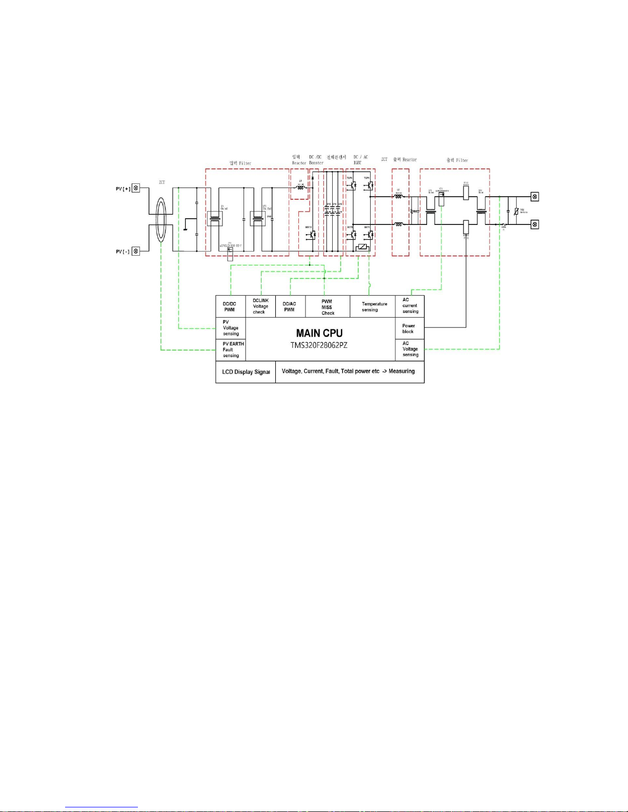
2.1.8 Specific Features of the Product
(1) High Efficiency Power Conversion
The inverter converts the power in a high efficiency using IGBT and has high an efficiency characteristic of
96% or more at rated power.
(2) Digital Control
It’s more convenient to control the system through digital control with high performance. You can check the
system through LCD keypad. LCD screen monitors and indicates the present condition of operation, input
and output and any abnormality of the inverter. And its operation stops in the event of any error. It detects
the voltage of solar cells to operate or stop automatically.
High voltage
distribution line
Low voltage
distribution line
Solar cell array
Interlocked protection device
Cabinet panel
Watt-hour meter
Outdoor switch
PCS(Inverter)
Washing machine
Refrigerator
Load
Air conditioner
Incoming line
Commercial
system

7
(3) Transformer-less circuit
DSP-123K5-OD inverter is of transformer-less type and is suitable for the decentralized power system
designed for industry, building and residential purpose.
(4) Decentralized Power System and Profitability
Photovoltaic power generation is a power generation type which can be installed wherever the sun shines
exists. The decentralized power by unit of building, housing complex and photovoltaic generating plant
enables to use the system economically.
(5) MPPT (Maximum Power Point Tracking)
As the uneven direct current is generated as per ambient temperature, humidity, climate, environment and
radiation for the characteristic of solar cells, the inverter controls the solar cells tracks to maintain the
maximum power point through MPPT.
(6) Easy Parallel Operation
If the capacity of solar cells increases, the inverter can be added and connected for extension of capacity
without any additional equipment.
(7) Convenient Installation and Operation
This product is designed for more easy and safe connection of the solar cells to the system power. Through
frontal LCD keypad, it is designed to display the present condition of converter and you can stop the
operation manually.
(8) High Reliability and Low Noise
The components of the inverter are optimized to reduce the causes for defaults. Especially, the inverter
cooling fan that has a limited mechanical life time is removed to realize high reliability and low noise.
(9) Electromagnetic Compatibility(EMC)
By optimizing Pattern Generation of inverter, inverter is manufactured to be suitable for EMC standard.
(KSC IEC 61000-6-1, KSC IEC 61000-6-3, KSC IEC 61000-6-4)
8
2.2 Specification
Model NO.
DSP-123K5-OD
Input
Voltage range(25 ℃)
100V ~ 500V
MPPT Voltage range(25 ℃)
100V ~ 400V
Rated voltage(25 ℃)
350V
Start voltage(25 ℃)
150V
Control method
Max. Power Point Tracking control(MPPT)
Output
Rated output
3.1 kW
Rated voltage
Grid Voltage (AC 220V +10%/-12%)
Frequency change rate
Grid Frequency (60Hz +0.5Hz/-0.7Hz)
Grid connection
Single Phase 2 Wire
Power factor
0.95 or above
Current distortions
Total below 5%
Individual Harmonics 3% or under
Control method
PWM Method
Anti-islanding
Within 0.5 sec
Overload
110%
Efficiency
97.21% (Maximum) / 96.76% (Euro)
Structure
Cooling method
Natural air cooling
Protection structure
IP 65, Outdoor
Equipment noise
50 dB or less
External dimension
(W x L x H)
305 * 380 * 135.5 mm
Full weight
9.9kg
External interface
RS 485
Monitoring Device(Option)
DSP-WR5/DSP-ZR5(Wire/Wireless, RS485/232)
Protection
Function
Inverter
Input overvoltage, short circuit of output, over-load, overheating,
short of fuse and preventing DC output leakage
System
Anti-islanding(IEEE1547), Over/Under voltage of grid,Over/Under
frequency of grid
Environment
for
Operation
Ambient temperature
-20 ℃~ 50 ℃
Preserving temperature
-20 ℃~ 65 ℃
Ambient humidity
Below 90% RH (Under no Dewfall)
Altitude & vibration
1,000 m or less ·5.9m/sec²(=0.6g) or less
Ambient temperature
Shall be no corrosive gas, flammable gas, oil mist and dust
※Specifications ofthis product may be changed withoutprior notice for qualityimprovement, etc. Please inquiryat the time ofpurchase..
9
3. Installation
3.1 Configuration
1) DSP-123K5-OD
3.2 Installation place
Install the Solar Inverter at the place satisfying following conditions.
1) Do not install the inverter at the place where the vibration exists.
2) As the lifetime of inverter is affected by surrounding temperature, make sure that the surrounding temperature
around the place where the inverter is installed is lower than the allowable temperature (-10 ~ 50℃).
3) Avoid hot and humid place (Relative humidity should be less than 90%. No dewfall).
4) Install the inverter at the place with no direct sun shine.
5) As the inverter is a high temperature unit which generates the heat, it should be installed at the face of non-
flammable material.
6) Secure the sufficient space around the inverter so as to install it for efficient dissipation of the heat.
7) Avoid the place where oil mist, flammable gas, fabric mote, dust and moisture do not exist.
8) Install the inverter by tightening the screws firmly.
9) Install the inverter at the place where no salt exists.
10
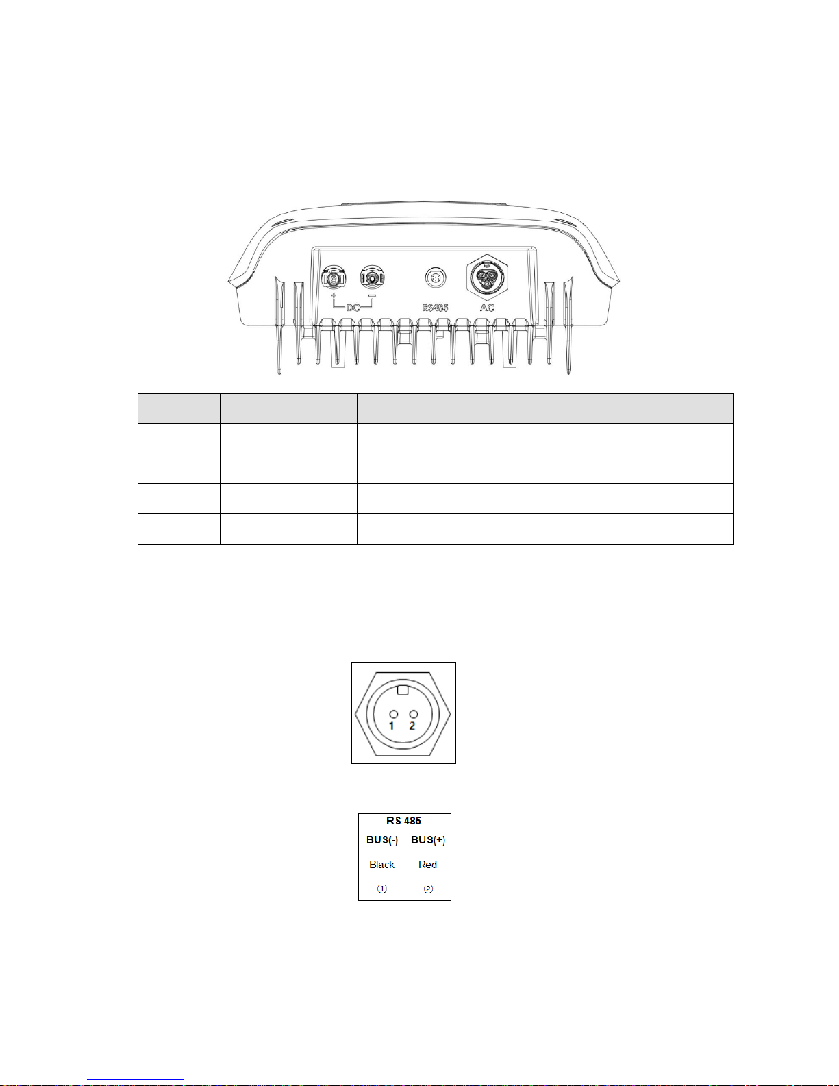
3.3 Terminal connection diagram
If you uncover the cover in front on the lower part of inverter, you can find the terminal blocks as below.
Read carefully this terminal connection diagram for wiring.
1) Description on main circuit terminal
Terminal
symbol
Terminal name
Description on terminals
DC [+]
Solar input power (+)
Connected with (+) of Solar cell power
DC [-]
Solar input power (-)
Connected with (-) of Solar cell power
RS485
Communication
terminal
Connect to signal line of the monitoring system
AC
Grid power connection
terminal
Inverter output is connected to grid power & ground lines
2) Description on RS 485C Communication terminal and connectors.
Communication Output Port:
Communication Connector terminal:
(RS232/485 Communication terminals are connected as shown on the figure above and do not touch the metal part of the connector
(conductor part). It may cause electric shock.)

11
For parallel operation(more than 2 inverters) and using monitoring, 485 communication terminal resistancedddd
ON/OFF switch
3.4 Wiring
3.4.1 Main circuit wiring
1) Cautions for main circuit wiring
For input power, connect the inverter’s inside connector [+] to the inverter’s outside connector [+] and the
inverter inside connector’s [-] to the inverter outside connector [-], then supply power. The inverter might be
damaged by wrong connection.
Do not disconnect the connecter while at power.
Keep in mind that the internal capacitor of the inverter is charged even if the power is off.
To prevent electric shock, the inverter must be earthed. Make sure that the resistance of earth is 100 mΩ or less.
Connect the terminal of the inverter to the exclusive terminal block. Do not use a case or sash screw as an
earth terminal.
For earth wire, use exclusive earth wire complying with the standard. Connect the earth terminal to the spot
adjacent to the inverter. The earth cable must be 4.0mm²or more.
Confirm the maximum input voltage of inverter and output voltage of solar panel. If the output voltage of solar
panel exceeds the maximum input voltage of inverter, the critical damage can occur to the product.
Power
Size of earth cable( mm²)
1.5 ~ 3 kW
4.0
5 kW
6.0
Confirm the maximum input voltage of inverter and output voltage of solar panel. If the output voltage of solar
panel exceeds the maximum input voltage of inverter, the critical damage can occur to the product.
For the wiring of solar panel, check the temperature coefficient to set the output voltage. Otherwise, input
over-voltage or low-voltage of inverter can occur due to the ambient temperature.
485communication
Terminal resistance connection : ON
Terminal resistance release : OFF
12
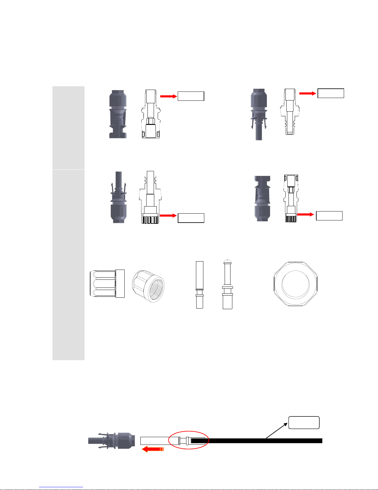
2) Configuration and installation for DC connector
Configuration
Inverter
Inside
Connecter
[ + ] Pole / Inner diagram
[ - ] Pole / Inner diagram
Inverter
Outside
Connecter
( + ) Pole / Inner diagram
( - ) Pole / Inner diagram
①CAP : tightening form when
connecting cable and terminal
④Terminal used when
connecting cable and
connector
⑤Nut to fix the connecter
inside the inverter
※To easily classify Inside Connector and Outside Connector is to check the difference in connection part of rear
cap. When tightening, tighten the same pole shown in the connector.
Installation
Step 1. Coupling method of cable terminal and connector
①Compress cable and terminal
Cable
Terminal
Terminal
Terminal
Terminal
[+]
13
※Terminal coupling method is only connectable with terminal and connector shown above
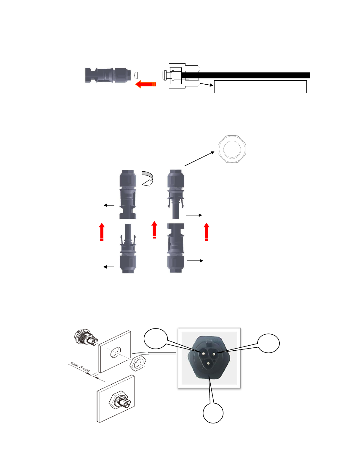
Step 2. Connection method of connector and inverter
※Notice : Connect only the same polarity shown above [[+] ↔ [+] , [-] ↔ [-]]
2) AC Connector wiring
Connector [+] Terminal
Connector [+] Terminal
Connector [-] Terminal
Turn the nut to be fixed
Nut
Connector [-] Terminal
②Connect the connector to the cable which is connected to terminal
CAP is only used for PV connector
[-]
FG
N
L
14
3.4.2 Communication circuit wiring
1) Notice of the communication circuit wiring
Wiring of Control circuit terminal is to be used for communication connector. See the wiring diagram 3.3.
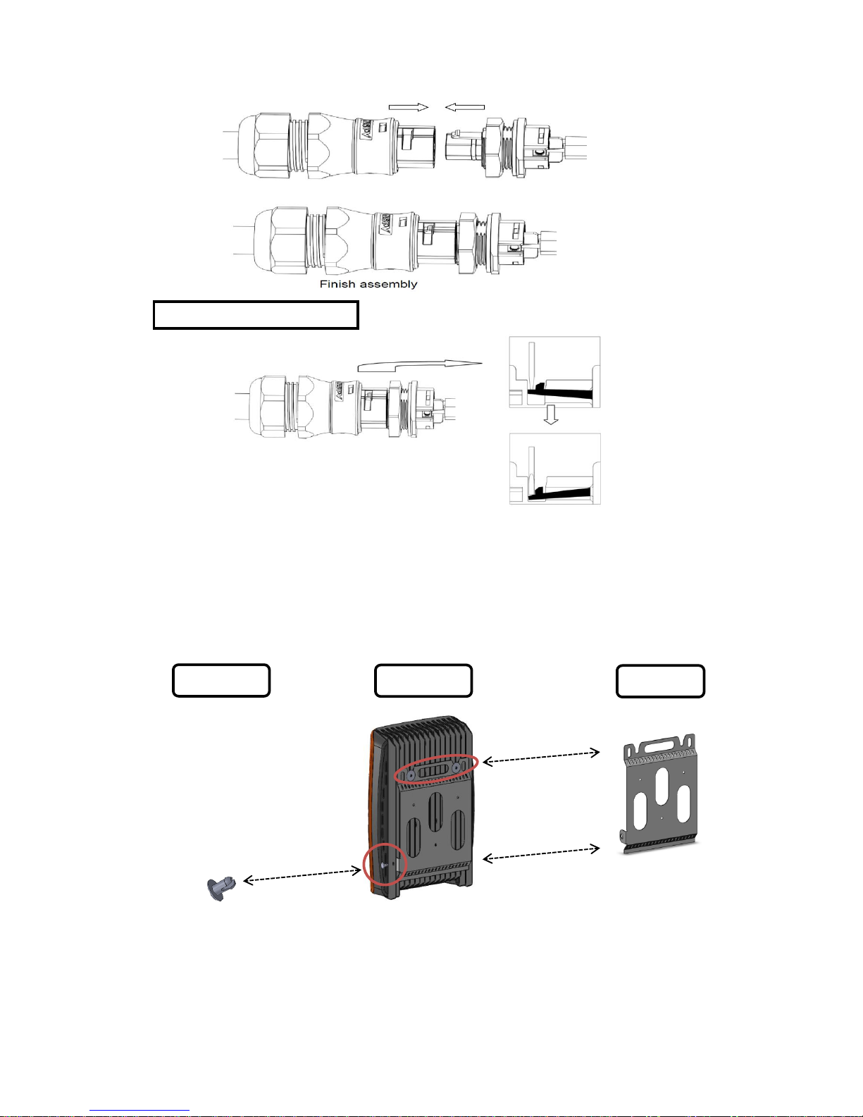
3.5 Cautions for mounting the inverter to the wall
▶Installation ①Remove (press fit) spanner for the inverter by using a tool(like long nose plier)
②Remove Wall BKT from the inverter and mount Wall BKT to the wall
③Install the inverter to Wall BKT and fix it by the (press fit) spanner
Unlocking & Separating
(Press fit)
Spanner
Inverter
Wall BKT

15
4. Operation
4.1 Display
4.1.1Appearance
4.1.2Functions of display
LED Status
Description
Input (입력)
Indicates the input status from solar modules.
(Green light: solar module is in normal operation)
Grid (한전)
Indicates the grid power system status. (Green light : grid power system is normal)
Operation (운전)
Indicates the operation status of the inverter.
(Green light : inverter generation is normal, Red flickering : ‘Fault’)
4.2 Basic mode (2 lines 16 characters LCD)
When the inverter power is ON, information on the LCD is updated every 10 second.
4.2.1 Input power (DC)
Display Input voltage Input current
PV: solar module D.C voltage D.C current
▶▶▶▶▶▶▶▶▶▶ Present power generated
4.2.2 Grid power input
Display Grid frequency Grid current
Line : grid frequency grid current
▶▶▶▶▶▶▶▶▶▶ Grid voltage
→PV 412V 7.7 A
▶▶▶▶▶▶▶▶▶▶ 3.1 kW
→LINE 50Hz 14.1A
▶▶▶▶▶▶▶▶▶▶ 230.0 V
16
4.2.3 Total generated power
Display Unit
Total : total generated power kWh
▶▶▶▶▶▶▶▶▶▶ Present power generated
4.2.4 Maximum(Peak) generated power
Display Unit
Peak : maximum generation kW
▶▶▶▶▶▶▶▶▶▶ Present power generated
4.2.5 Daily(today) generated power
Display Unit
Today : today’s generated power Wh
▶▶▶▶▶▶▶▶▶▶ Present power generated
4.2.6 Daily (previous day) generated power
Display Unit
DAY-1 : previous day’s generated power Wh
▶▶▶▶▶▶▶▶▶▶ Present power generated
4.2.7 Present power generated
Display Unit
RUN : operation status kW
▶▶▶▶▶▶▶▶▶▶ Generated power(%)
→Total 500 kWh
▶▶▶▶▶▶▶▶▶▶ 3.1 kW
→Peak 3.1 kW
▶▶▶▶▶▶▶▶▶▶ 3.0 kW
→TODAY 1000 Wh
▶▶▶▶▶▶▶▶▶▶ 3.1 kW
→DAY-1 1500 Wh
▶▶▶▶▶▶▶▶▶▶ 3.1 kW
→RUN 3.1kW
▶▶▶▶▶▶▶▶▶▶ 97.2%

17
4.2.8 Fault status (Displayed for 5 seconds)
Display Type of error
Fault number : number of times
Fault status
4.3 Operation method
4.3.1 Check points prior to operation
-. Check the wiring and installation status of the inverter.
-. Especially, check that input polarity of solar module has been connected correctly and the line to grid has
been connected correctly.
-. Direct power of solar panel is supplied to the inverter and AC power status is checked, then the inverter
operates automatically after 300 seconds
(If necessary, a DC circuit breaker can be installed outside the inverter)
4.3.2 Automatic operation
The inverter is set to auto-operation mode as default setting when shipped from the factory.
The inverter operates automatically when the voltage of the solar panel is over setting value after sunrise and the
inverter stops automatically when voltage of the solar panel is under setting value after sunset.
The inverter always monitors the grid power and it stops automatically in abnormal status.
5. Function
5.1 Descriptions
5.1.1 Grid monitoring
Whether the system voltage is normal or abnormal is determined by the difference from the normal voltage (Fault
high voltage, Fault low voltage), and if this value is higher or lower than the specified value, it stops the inverter.
If the frequency of system voltage is off the line frequency by line fault frequency, it stops the inverter’s operation.
In order to start the generation at the normal system status, it operates with the system after the line transition time
elapses. Frequency of used system voltage can be set in accordance with the frequency band.
5.1.2 MPPT control and total power generation
As the output of solar panel varies on surrounding temperature, humidity and solar ray intensity, MPPT
(Maximum Power Point Tracking) algorithm should be carried out smoothly. The method applied to this product
does not show the fluctuation in current, and it stops the inverter when the solar cells reach the PV stop voltage
and the inverter cannot be operated anymore.
[001] E008
Under Voltage

18
As the accumulated total power is stored, total generation power can be checked.
5.1.3 Initialization and action for abnormality
In case the inverter stops due to any errors, error indication is shown on the screen. At this time, examine the
reason why any error occurs, remove the fault cause and then re-run the inverter. When the same problem
happens or the inverter does not re-run, you should contact Dass tech or Installer.
Fault scan is stored 100 in the order in which they were generated in the past from 0 to 99 and the most recent
one is No. 0. By using the Up/Down key on the keypad inside the inverter, it is able to find out the situations of
the fault occurrences from the past or variables.
When the inverter is stopped, it is able to change the parametric value by using the inner keypad.
There are two initializations, which is Parameter initialization and Fault initialization. Parameter initialization
sets every parameter or selection function to the Factory Default, and Fault initialization deletes the fault records
occurred in the past and sets to ‘ready’mode.
Controlling the inner keypad randomly shall cause malfunction of the inverter. You should contact DASS tech..
5.1.4 Fault
1) Fault
Input Overvoltage (DC OV)
In case the voltage of solar cells is higher than the specified value, stop the system to protect the inverter.
Output Over-current (Over current)
In case the output current of the inverter is over-current due to abnormal load status, stop the system to protect
the inverter.
Inverter Overheat (Over heat)
In case the temperature inside the inverter is higher than 95℃, stop the system to prevent overheat. If the
temperature inside the inverter returns to normal, operate the inverter normally after reset.
Earth fault
In case the current leaks due to abnormal earth, stop the system.
Line failure (Over/Under frequency, Over/Under voltage)
When abnormality occurs in the grid power, stop the system. (Anti-islanding, protection of system over/under-
voltage, protection of system low voltage, protection of system over/under-frequency, protection of system low-
frequency)
Abnormal PWM control (Over current 2)
If there is abnormal status found in PWM control inside the inverter, stop the system
19
6. Maintenance & repair
6.1 Types of error
If any error occurs, it indicates such error and stops operation.
When abnormal, its contents are displayed on the window of the keypad.
Causes of faults and corrective actions
Fault
Code
Type
Indication
Causes of errors
Corrective actions
E001
Input
Over-current
PV Error
Over current from solar module
Check the solar module then operate the inverter.
If the problem isn’t solved, contact us.
E002
Input
Over-voltage
DC OV
Over voltage from solar module
Check the solar module then operate the inverter.
If the problem isn’t solved, contact us.
E004
Input
DC-LINK
Over-voltage
DC-Link OV
Over voltage from DC-LINK of
the inverter
Check the solar module then operate the inverter.
If the problem isn’t solved, contact us.
E005
Input
DC-LINK
Under-voltage
DC-Link UV
Under voltage from DC-LINK
of the inverter
Check the solar module then operate the inverter.
If the problem isn’t solved, contact us.
E006
Grid
Over-current
Over Current
Over current in grid output
Check grid status and contact your electricity authority.
Then if the problem isn’t solved, contact us
E007
Grid
Over-voltage
Over voltage
Abnormal grid voltage
Check grid status and contact your electricity authority.
Then if the problem isn’t solved, contact us
E008
Grid
Under-voltage
Under voltage
Abnormal grid voltage
Check grid status and contact your electricity authority.
Then if the problem isn’t solved, contact us
E010
Grid
Over-frequency
Over
frequency
Abnormal grid frequency
Check grid status and contact your electricity authority.
Then if the problem isn’t solved, contact us
E011
Grid
Under-frequency
Under
frequency
Abnormal grid frequency
Check grid status and contact your electricity authority.
Then if the problem isn’t solved, contact us
E019
PWM fault
(Input)
Over
Current 2
Inverter’s internal problem
Contact us immediately
E020
PWM fault
(Output)
Over
Current 2
Inverter’s internal problem
Contact us immediately
E022
Over heating
Over
heat
Inverter’s over heating
Pls. try to operate inverter and if the problem isn’t solved,
pls. contact us immediately
E023
Earth fault
(DC)
Earth fault
Leakage of current
(Short circuit status)
Check earth and insulation status then, if the problem isn’t
solved, contact us.
E030
Consecutive fault
Cont. fault
Same fault happens
consecutively
Pls. try to operate inverter and if the problem isn’t solved,
pls. contact us immediately
Table of contents
Other Dass Inverter manuals

Popular Inverter manuals by other brands

gefran
gefran RADIUS APV 1700-2M-TL-US Installation & operation manual

Deye
Deye SUN-6K-SG03LP1-EU user manual

Western
Western Leonardo Off-Grid 4kW-5000-48 MG user manual

Wagan
Wagan Smart AC user manual

Rinnai
Rinnai EVT20A Operation & installation manual

Black & Decker
Black & Decker MAXX SST instruction manual


