Asterion HYBRID 30K User manual

USER MANUAL
Inverter/charger ASTERION HYBRID 30K
Version: 1.0

2
Table Of Contents
1. Introduction ...................................................................................................4
2. Important Safety Warning .............................................................................5
3. Unpacking & Overview .................................................................................7
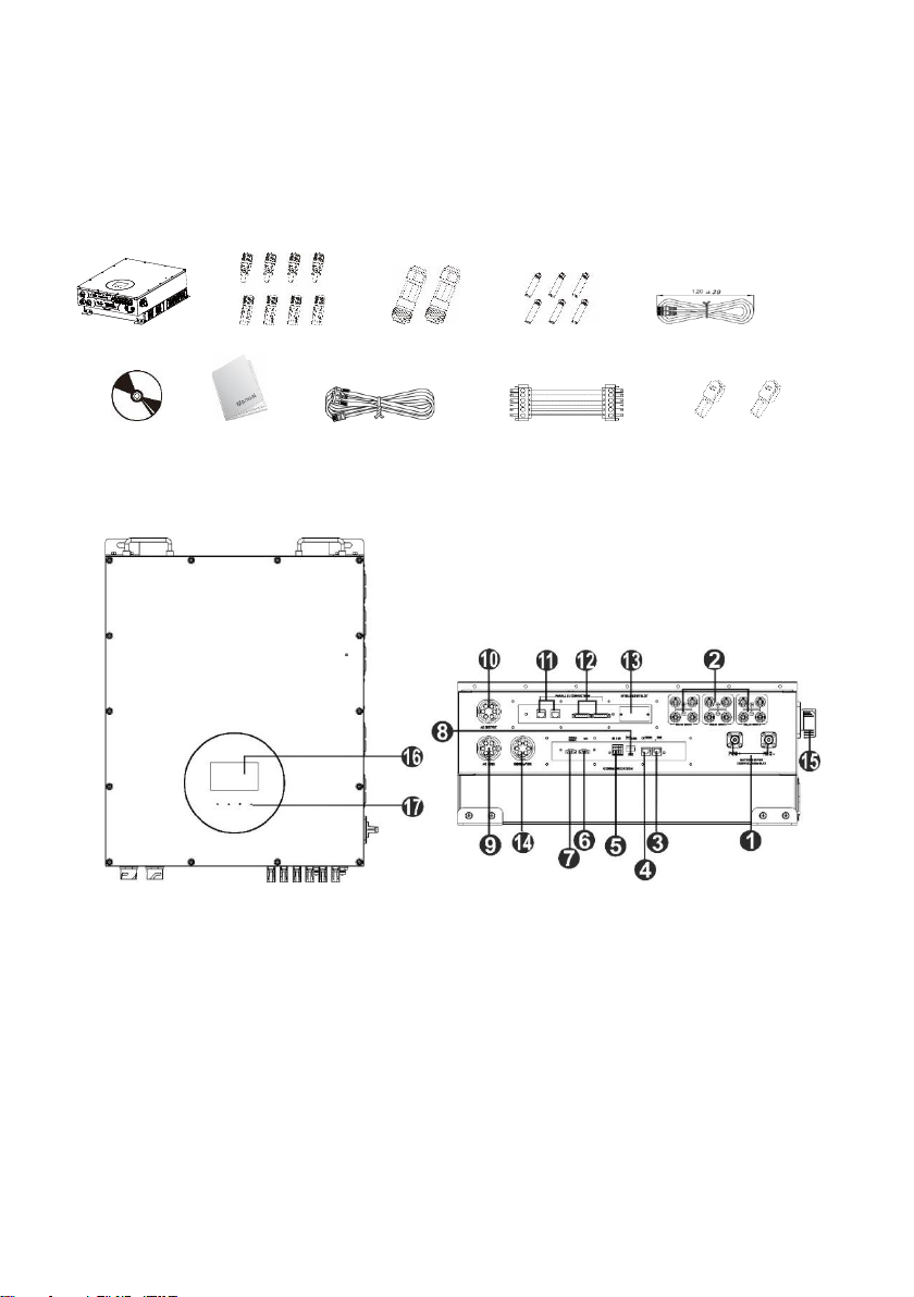
3-1. Packing List............................................................................................7
3-2. Product Overview...................................................................................7
4. Installation.....................................................................................................7
4-1. Precaution ..............................................................................................8
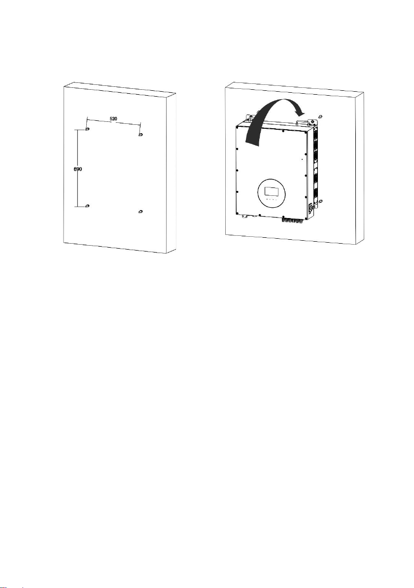
4-2. Selecting Mounting Location..................................................................8
4-3. Mounting Unit .........................................................................................8
5. Grid (Utility) Connection .............................................................................10
5-1. Preparation ..........................................................................................10
5-2. Connecting to the AC Utility .................................................................10
6. Generator Connection ................................................................................12
6-1. Preparation ..........................................................................................12
6-2. Connecting to the Generator input.......................................................12
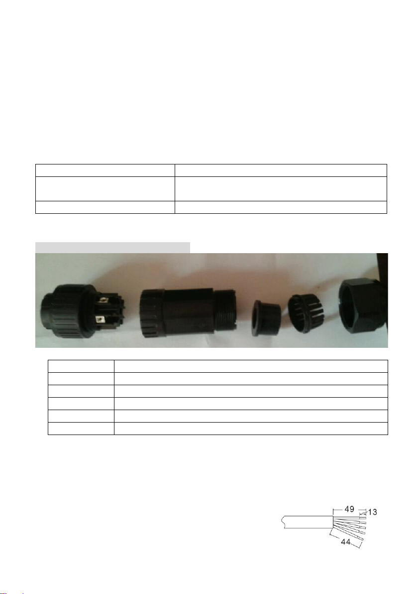
7. PV Module (DC) Connection ......................................................................14
8. Battery Connection .....................................................................................18
9. Load (AC Output) Connection ....................................................................19
9-1. Preparation ..........................................................................................19
9-2. Connecting to the AC output................................................................19
10. Communication Connection .......................................................................21
11. Dry Contact Signal........................................................................................21
11-1. Electric Parameter..............................................................................22
11-2. Function Description ..........................................................................22
12. Application with Energy Meter ......................................................................23
13. Commissioning.............................................................................................25
14. Initial Setup...................................................................................................26
15. Operation......................................................................................................38
15-1. Interface .............................................................................................38
15-2. LCD Information Define .....................................................................38
15-3. Button Definition.................................................................................40
15-4. LCD Setting........................................................................................41
15-5. Query Menu Operation ......................................................................51
15-6. Operation Mode & Display.................................................................58
16 Charging Management ...............................................................................63
17. Maintenance & Cleaning ............................................................................65
18. Trouble Shooting ..........................................................................................66
18-1. Warning List .......................................................................................66
18-2. Fault Reference Codes ......................................................................67

3
19. Specifications ...............................................................................................71
Appendix I: Parallel Installation Guide ...............................................................73
Introduction..................................................................................................73
Parallel cable...............................................................................................73
Overview .....................................................................................................73
Mounting the Unit ........................................................................................74
Wiring Connection.......................................................................................74
Inverters Configuration................................................................................76
Setting and LCD Display .............................................................................78
Commissioning............................................................................................81
Trouble shooting..........................................................................................82
Appendix II: BMS................................................................................................83

4
1. Introduction
This hybrid PV inverter can provide power to connected loads by utilizing PV
power, utility power and battery power.
Battery
Figure 1 Basic hybrid PV System Overview
Depending on different power situations, this hybrid inverter is designed to
generate continuous power from PV solar modules (solar panels), battery, and
the utility. When MPP input voltage of PV modules is within acceptable range (see
specification for the details), this inverter is able to generate power to feed the
grid (utility) and charge battery. This inverter is only compatible with PV module
types of single crystalline and poly crystalline. Do not connect any PV array types
other than these two types of PV modules to the inverter. Do not connect the
positive or negative terminal of the solar panel to the ground. See Figure 1 for a
simple diagram of a typical solar system with this hybrid inverter.
Note: By following the EEG standard, every inverter sold to German area is not
allowed to charge battery from Utility. The relevant function is automatically
disabled by the software.
PV modules
Hybrid inverter
Distribution Box
Electric grids
Load

5
2. Important Safety Warning
Before using the inverter, please read all instructions and cautionary
markings on the unit and this manual. Store the manual where it can be
accessed easily.
This manual is for qualified personnel. The tasks described in this manual may
be performed by qualified personnel only.
General Precaution-
WARNING! Before installing and using this inverter, read all instructions and
cautionary markings on the inverter and all appropriate sections of this guide.
WARNING! Normally grounded conductors may be ungrounded and energized
when a ground fault is indicated.
WARNING! This inverter is heavy. It should be lifted by at least two persons.
CAUTION! Authorized service personnel should reduce the risk of electrical
shock by disconnecting AC, DC and battery power from the inverter before
attempting any maintenance or cleaning or working on any circuits connected to
the inverter. Turning off controls will not reduce this risk. Internal capacitors can
remain charged for 5 minutes after disconnecting all sources of power.
CAUTION! Do not disassemble this inverter yourself. It contains no user-
serviceable parts. Attempt to service this inverter yourself may cause a risk of
electrical shock or fire and will void the warranty from the manufacturer.
CAUTION! To avoid a risk of fire and electric shock, make sure that existing wiring
is in good condition and that the wire is not undersized. Do not operate the
Inverter with damaged or substandard wiring.
Conventions used:
WARNING! Warnings identify conditions or practices that could result in personal
injury;
CAUTION! Caution identify conditions or practices that could result in damaged to the
unit or other equipment connected.

6
CAUTION! Under high temperature environment, the cover of this inverter could
be hot enough to cause skin burns if accidentally touched. Ensure that this
inverter is away from normal traffic areas.
CAUTION! Use only recommended accessories from installer. Otherwise, not-
qualified tools may cause a risk of fire, electric shock, or injury to persons.
CAUTION! To reduce risk of fire hazard, do not cover or obstruct the cooling fan.
CAUTION! Do not operate the Inverter if it has received a sharp blow, been
dropped, or otherwise damaged in any way. If the Inverter is damaged, please
call for an RMA (Return Material Authorization).
CAUTION! AC breaker, DC switch and Battery circuit breaker are used as
disconnect devices and these disconnect devices shall be easily accessible.
Symbols used in Equipment Markings
Refer to the operating instructions
Caution! Risk of danger
Caution! Risk of electric shock
Caution! Risk of electric shock. Energy storage timed
discharge for 5 minutes.
Caution! Hot surface
Before working on this circuit
-Isolate inverter/Uninterruptible Power System (UPS)
-Then check for Hazardous Voltage between all
terminals including the protective earth.
Risk of Voltage Backfeed

7
3. Unpacking & Overview
3-1. Packing List
Before installation, please inspect the unit. Be sure that nothing inside the
package is damaged. You should have received the following items inside of
package:
Inverter unit PV connectors AC connectors Fixing screws Parallel cable
Software CD Manual RS-232 cable Share current cable battery
plugs
3-2. Product Overview
1) Battery connectors
2) PV connectors
3) RS-232 communication port
4) BMS
5) Dry contact
6) EPO
7) Battery thermal sensor
8) USB communication port
9) AC Grid connectors
10) AC output connectors (Load
connection)
11) Parallel communication port
12) Current sharing port
13) Intelligent slot
14) Generator input
15) PV switch
16) LCD display panel (Please check
section 10 for detailed LCD operation)
17) Touchable buttons
18) Installation

8
4-1. Precaution
This Hybrid inverter is designed for indoor or outdoor use (IP65), please make
sure the installation site meets below conditions:
⚫Not in direct sunlight
⚫Not in areas where highly flammable materials are stored.
⚫Not in potential explosive areas.
⚫Not in the cool air directly.
⚫Not near the television Antenna or antenna cable.
⚫Not higher than altitude of about 2000 meters above sea level.
⚫Not in environment of precipitation or humidity (>95%)
Please AVOID direct sunlight, rain exposure, snow laying up during installation
and operation.
4-2. Selecting Mounting Location
⚫Please select a vertical wall with load-bearing capacity for installation,
appropriate for installation on concrete or other non-flammable surfaces.
⚫The ambient temperature should be between -25~60℃ to ensure optimal
operation.
⚫Be sure to keep other objects and surfaces as shown in the diagram to
guarantee sufficient heat dissipation and have enough space for removing
wires.
⚫For proper air ventilation to dissipate heat, allow a clearance of approx. 50cm
to the side and approx. 50cm above and below the unit. And 100cm toward
the front.
4-3. Mounting Unit
Installation to the wall should be implemented with the proper screws. After that,
the device should be bolted on securely.
WARNING!! FIRE HAZARD.
SUITABLE FOR MOUNTING ON CONCRETE OR OTHER NON-COMBUSTIBLE SURFACE
ONLY.
WARNING!! Remember that this inverter is heavy! Please be carefully when lifting out
from the package.

9
1. Drill four holes in the marked
locations with supplied four
screws. The reference
tightening torque is 35 N.m.
2. Fix the inverter on the wall.
3. Check if the inverter is firmly
secured.

10
4. Grid (Utility) Connection
5-1. Preparation
NOTE: The overvoltage category of the AC input is III. It should be connected to
the power distribution.
NOTE2: The inverter is built in a 63A/400V breaker to protect the inverter from
AC power damage.
WARNING! It's very important for system safety and efficient operation to use
appropriate cable for grid (utility) connection. To reduce risk of injury, please use
the proper recommended cable size as below.
Suggested cable requirement for AC wire:
Nominal Grid Voltage
230VAC per phase
Conductor cross-section
(mm2)
9-10
AWG no.
8
5-2. Connecting to the AC Utility
Overview of AC Connection Socket
Component
Description
A
Pressure dome
B
Clip
C
Sealing nut
D
Protective element
E
Socket element
Step 1: Check the grid voltage and frequency with an AC voltmeter. It should be
the same to “VAC” value on the product label.
Step 2: Turn off the circuit breaker.
Step 3: Remove insulation sleeve 13 mm for five conductors.
Step 4: Thread the five cables through pressure
dome (A), clip (B), sealing nut (C) and protective
element (D) in sequence.
Step 5: Thread five cables through socket element
A
B
C
D
E

11
(E) according to polarities indicated on it and tighten the screws to fix wires after
connection.
L1→ LINE 1 (Black)
L2→ LINE 2 (Grey)
L→ LINE 3 (Brown)
→ Ground (Yellow-Green)
N→ Neutral (Blue)
The reference tightening torque is 4-5 N.m.
Step 6: Push protective dome (D) on to socket element (E) until both are locked
tightly. Then, twist protective element (D) and pressure dome (A) so that all cables
are firmly connected.
Step 7: Plug the AC connection socket into AC INPUT terminal of the inverter.
CAUTION: To prevent risk of electric shock, ensure the ground wire is properly earthed
before operating this hybrid inverter no matter the grid is connected or not.

12
6. Generator Connection
6-1. Preparation
NOTE: An additional disconnection device should be placed on in the building
wiring installation.
WARNING! It's very important for system safety and efficient operation to use
appropriate cable for AC connection. To reduce risk of injury, please use the
proper recommended cable size as below.
Suggested cable requirement for AC wire:
Nominal AC Voltage
230VAC per phase
Conductor cross-section
(mm2)
9-10
AWG no.
8
6-2. Connecting to the Generator input
Overview of AC Connection Socket
Component
Description
A
Pressure dome
B
Clip
C
Sealing nut
D
Protective element
E
Socket element
Step 1: Check the grid voltage and frequency with an AC voltmeter. It should be
the same to “VAC” value on the product label.
Step 2: Turn off the circuit breaker.
Step 3: Remove insulation sleeve 13 mm for five conductors.
Step 4: Thread the five cables through pressure
dome (A), clip (B), sealing nut (C) and protective
element (D) in sequence.
Step 5: Thread five cables through socket element
(E) according to polarities indicated on it and tighten the screws to fix wires after
connection.
A
B
C
D
E

13
L1→ LINE 1 (Black)
L2→ LINE 2 (Grey)
L→ LINE 3 (Brown)
→ Ground (Yellow-Green)
N→ Neutral (Blue)
The reference tightening torque is 4-5 N.m.
Step 6: Push protective dome (D) on to socket element (E) until both are locked
tightly. Then, twist protective element (D) and pressure dome (A) so that all cables
are firmly connected.
Step 7: Plug the Generator connection socket into GENERATOR terminal of the
inverter.
CAUTION: To prevent risk of electric shock, ensure the ground wire is properly earthed
before operating this hybrid inverter no matter the grid is connected or not.

14
7. PV Module (DC) Connection
NOTE1: The overvoltage category of the PV input is Ⅱ.
NOTE2: Please use 1000VDC/35A circuit breaker.
Please follow below steps to implement PV module connection:
Step 1: Check the input voltage of PV array modules. The acceptable input
voltage of the inverter is 350VDC - 1000VDC. This system is only applied with
three strings of PV array. Please make sure that the maximum current load of
each PV input connector is 26A.
Step 2: Disconnect the circuit breaker and switch off the DC switch.
Step 3: Assemble provided PV connectors with PV modules by the following
below steps.
Components for PV connectors and Tools:
Female connector housing
Female terminal
Male connector housing
CAUTION: Exceeding the maximum input voltage can destroy the unit!! Check the
system before wire connection.
WARNING: Because this inverter is non-isolated, only two types of PV modules are
acceptable: single crystalline and poly crystalline with class A-rated.
To avoid any malfunction, do not connect any PV modules with possibility of leakage
current to the inverter. For example, grounded PV modules will cause leakage current to
the inverter.
CAUTION: It’s requested to have PV junction box with surge protection. Otherwise, it
will cause inverter damage when lightning occurs on PV modules.

15
Male terminal
Crimping tool and spanner
Cable preparation and connector assembly process:
Strip two cables 8 mm on one side and be careful NOT to
nick conductors.
Insert striped cable into female terminal and crimp female terminal as shown
below charts.
Insert assembled cable into female connector housing as shown below charts.
Reference insertion force: ≦ 50N
Reference withdrawal force: ≧ 50N
Insert striped cable into male terminal and crimp male terminal as shown below
charts.
Insert assembled cable into male connector housing as shown below charts.
Reference insertion force: ≦ 50N
Reference withdrawal force: ≧ 50N
Then, use spanner to screw pressure dome tightly to female connector and male
connector as shown below.

16
The reference Nut cap locking force is 2.0~2.5Nm.
Step 4: Check correct polarity of connection cable from PV modules and PV input
connectors. Then, connect positive pole (+) of connection cable to positive pole
(+) of PV input connector. Connect negative pole (-) of connection cable to
negative pole (-) of PV input connector.
WARNING! It's very important for system safety and efficient operation to use
appropriate cable for PV module connection. To reduce risk of injury, please use
the proper recommended cable size as below.
Nominal Grid Voltage
736VDC
Conductor cross-section
(mm2)
6-8
AWG no.
10
CAUTION: Do NOT touch the inverter to avoid electric shock. When PV modules are
exposed to sunlight, it may generate DC voltage to the inverter.
CAUTION: Never directly touch terminals of the inverter. It will cause lethal electric
shock.

17
Recommended PV module Configuration
PV Module
Spec.
(reference)
- 250Wp
- Vmp:
36.7Vdc
- Imp: 6.818A
- Voc: 44Vdc
- Isc: 7.636A
- Cells: 60
Total
input
power
Solar input
1
Solar input 2
Solar input
3
Q'ty of
modules
3000W
12pieces in
series
Χ
Χ
12pcs
6000W
12pieces in
series
2 strings in
parallel
Χ
Χ
24pcs
9000W
12pieces in
series
2 strings in
parallel
12pieces in
series
Χ
36pcs
12000W
12pieces in
series
2 strings in
parallel
12pieces in
series
2 strings in
parallel
Χ
48 pcs
15000W
12pieces in
series
2 strings in
parallel
12pieces in
series
2 strings in
parallel
12pieces in
series
60 pcs
18000W
12pieces in
series
2 strings in
parallel
12pieces in
series
2 strings in
parallel
12pieces in
series
2 strings in
parallel
72 pcs
21000W
14pieces in
series
2 strings in
parallel
14pieces in
series
2 strings in
parallel
14pieces in
series
2 strings in
parallel
84 pcs
24000W
16pieces in
series
2 strings in
parallel
16pieces in
series
2 strings in
parallel
16pieces in
series
2 strings in
parallel
96 pcs
27000W
18pieces in
series
2 strings in
parallel
18pieces in
series
2 strings in
parallel
18pieces in
series
2 strings in
parallel
108 pcs

18
30000W
20pieces in
series
2 strings in
parallel
20pieces in
series
2 strings in
parallel
20pieces in
series
2 strings in
parallel
120 pcs
8. Battery Connection
CAUTION: Before connecting to batteries, please install separately a DC circuit
breaker between inverter and batteries.
NOTE1: Please only use sealed lead acid battery, vented and Gel battery, lithium
battery. Please check maximum charging voltage and current when first using
this inverter. If using Lithium iron or Nicd battery, please consult with installer for
the details.
NOTE2: Please use 1000VDC/100A circuit breaker.
NOTE3: The overvoltage category of the battery input is II.
Please follow below steps to implement battery connection:
Step 1: Check the nominal voltage of batteries. The nominal input voltage for
inverter is 736VDC.
Step 2: Turn off the circuit breaker.
Step 3: Use two 4AWG battery cables.
Remove insulation sleeve 10 mm and insert
one end of conductor into ring terminal.
Insert the other end of conductor into
battery plug. Refer to right chart.
Step 4: Plug the assembled battery cables to battery terminals of the inverter.
RED cable to the positive terminal (+);
BLACK cable to the negative terminal (-).
WARNING! Wrong connections will damage the unit permanently.

19
9. Load (AC Output) Connection
9-1. Preparation
CAUTION: To prevent further supply to the load via the inverter during any mode
of operation, an additional disconnection device should be placed on in the
building wiring installation.
WARNING! It's very important for system safety and efficient operation to use
appropriate cable for AC connection. To reduce risk of injury, please use the
proper recommended cable size as below.
Nominal Grid Voltage
208/220/230/240 VAC per phase
Conductor cross-section (mm2)
5.5-10
AWG no.
8 AWG
9-2. Connecting to the AC output
Overview of Load Connection Socket
Component
Description
A
Pressure dome
B
Clip
C
Sealing nut
D
Protective element
E
Socket element
Step 1: Remove insulation sleeve 8.5 mm for five conductors.
Step 2: Thread the five cables through pressure
dome (A), clip (B), sealing nut (C) and protective
element (D) in sequence.
Step 3: Thread five cables through socket element
(E) according to polarities indicated on it and
tighten the screws to fix wires after connection.
A
B
C
D
E

20
L1→ LINE 1 (Black)
L2→ LINE 2 (Grey)
L3→ LINE 3 (Brown)
→ Ground (Yellow-Green)
N→ Neutral (Blue)
The reference tightening torque is 1.0-1.5 N.m.
Step 4: Push protective dome (D) on to socket element (E) until both are locked
tightly. Then, twist protective element (D) and pressure dome (A) so that all cables
are firmly connected.
Step 5: Plug the socket into the terminal.
CAUTION: It’s only allowed to connect load to “AC Output Connector”. Do NOT connect
the utility to “AC Output Connector”.
CAUTION: Be sure to connect L terminal of load to L terminal of “AC Output Connector”
and N terminal of load to N terminal of “AC Output Connector”. The G terminal of “AC
Output Connector”is connected to grounding of the load. Do NOT mis-connect.
Table of contents
Popular Inverter manuals by other brands

PurePower
PurePower PP2100R Operator's manual

Hitachi
Hitachi RAD-50DH7A installation manual

Duracell
Duracell Digital Inverter 800 owner's guide

Senci
Senci SC2000i operating manual

Generac Power Systems
Generac Power Systems 005030-0 (15kW) owner's manual

Huawei
Huawei SUN2000-25KTL-US Quick installation guide