BLEMO ER24 Series Owner's manual
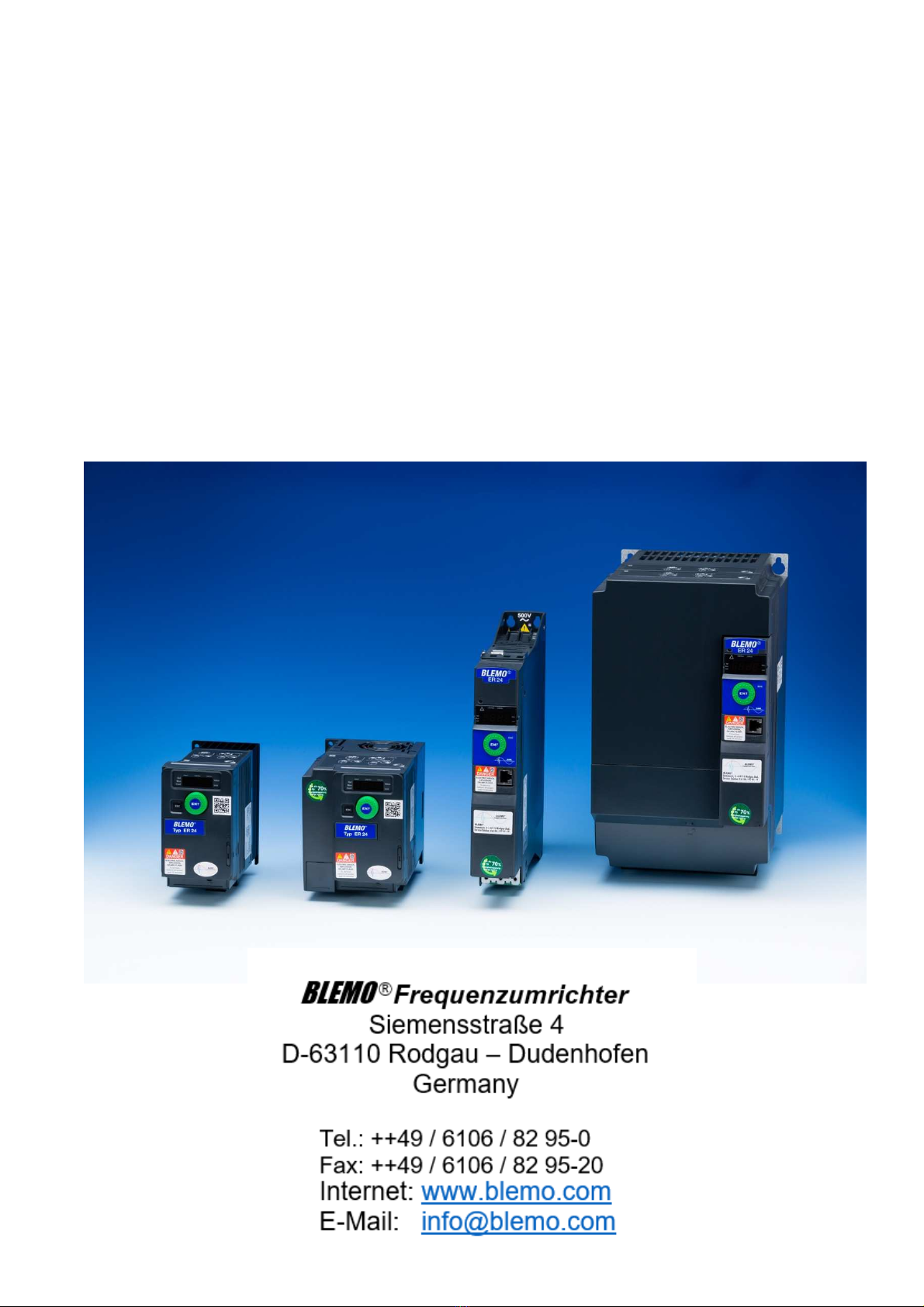
BLEMO
®
ER24
Variable Speed Drives
for Asynchronous and Synchronous Motors
Programming Manual
05/2018

2
The information provided in this documentation contains general descriptions and/or technical characteristics
of the performance of the products contained herein. This documentation is not intended as a substitute for
and is not to be used for determining suitabilityor reliabilityof these products for specific user applications. It
is the dutyof any such user or integrator to perform the appropriate and complete risk analysis, evaluation and
testing of the products with respect to the relevant specific application or use thereof. Neither BLEMO nor
any of its affiliates or subsidiaries shall be responsible or liable for misuse of the information contained
herein. If you have any suggestions for improvements or amendments or have found errors in this
publication, please notifyus.
No part of this docum ent maybe reproduced in anyform or byanymeans, electronic or mechanical, including
photocopying, without express written permission of BLEMO.
All pertinent state, regional, and local safety regulations must be observed when installing and using this
product. For reasons of safety and to help ensure compliance with documented system data, only the
manufacturer should perform repairs to components.
When devices are used for applications with technical safetyrequirements, the relevant instructions must be
followed.
Failure to use BLEMO software or approved software with our hardware products mayresult in injury, harm,
or improper operating results.
Failure to observe this information can result in injury or equipment damage.
© 2017 BLEMO. All rights reserved.

3
Table of Contents
Table of Contents
Safety Information .............................................................................................................7
About the Book................................................................................................................11
General Overview
........................................................................................................................15
Chapter 1 Overview...........................................................................................................................17
Factory configuration .........................................................................................................18
Application functions .........................................................................................................19
Basic functions ..................................................................................................................23
Graphic display terminal option.........................................................................................24
Powering up the drive for the first time .............................................................................27
Remote display terminal option.........................................................................................30
Structure of the parameter tables......................................................................................31
Finding a parameter in this document...............................................................................32
Description of the HMI.......................................................................................................33
Structure of the menus......................................................................................................35
Chapter 2 Setup.................................................................................................................................37
Steps for setting-up the drive ............................................................................................38
Initial steps.........................................................................................................................39
Programming
...............................................................................................................................41
Chapter 3 Reference Mode (rEF).....................................................................................................43
Introduction........................................................................................................................44
Organization tree ...............................................................................................................45
Menu..................................................................................................................................46
Chapter 4 Monitoring Mode (MOn)..................................................................................................47
Introduction........................................................................................................................48
Organization tree ...............................................................................................................49
Menu..................................................................................................................................50
[MONIT. MOTOR]
.......................................................................................................50
[I/O MAP]
...................................................................................................................51
[MONIT. SAFETY]
......................................................................................................54
[MONIT. FUN. BLOCKS]
.............................................................................................55
[COMMUNICATION MAP]
...........................................................................................56
[MONIT. PI]
................................................................................................................62
[MONIT. POWER TIME]
..............................................................................................62
[ALARMS]
..................................................................................................................63
[OTHER STATE]
........................................................................................................64
[DIAGNOSTICS]
.........................................................................................................64
[PASSWORD]
............................................................................................................75
Chapter 5 Configuration Mode (ConF)............................................................................................77
Introduction........................................................................................................................78
Organization tree ...............................................................................................................79
My Menu ............................................................................................................................80

4
Table of Contents
Factory Settings ................................................................................................................81
Macro Configuration ..........................................................................................................82
Full.....................................................................................................................................85
[SIMPLY START]
........................................................................................................85
[SETTINGS]
...............................................................................................................89
[MOTOR CONTROL]
................................................................................................105
[INPUTS / OUTPUTS CFG]
.......................................................................................125
[COMMAND]
............................................................................................................154
[FUNCTION BLOCKS]
..............................................................................................158
[APPLICATION FUNCT.] (FUn-)
................................................................................162
REFERENCE SWITCHING
..................................................................................167
REFERENCE OPERATIONS
...............................................................................168
RAMP
.............................................................................................................170
STOP CONFIGURATION
....................................................................................173
AUTO DC INJECTION
........................................................................................176
JOG
................................................................................................................178
PRESET SPEEDS
.............................................................................................180
+/- SPEED
........................................................................................................184
+/- SPEED AROUND A REFERENCE
....................................................................186
REFERENCE MEMORIZING
...............................................................................188
FLUXING BY LOGIC INPUT
................................................................................189
BRAKE LOGIC CONTROL
..................................................................................191
EXTERN AL WEIGHT MEASUREMENT
.................................................................199
HIGH SPEED HOISTING
....................................................................................201
PID REGULATOR
..............................................................................................206
PID PRESET REFERENCES
...............................................................................214
TORQUE LIMITATION
........................................................................................215
2ND CURRENT LIMITATION
...............................................................................218
DYN CURRENT LIMIT
........................................................................................219
LINE CONTACTOR COMMAND
...........................................................................220
OUTPUT CONTACTOR COMMAND
.....................................................................222
POSITIONING BY SENSORS
..............................................................................224
PARAMETER SET SWITCHING
...........................................................................229
MULTIMOTORS / MULTICONFIGURATIONS
.........................................................232
AUTO TUNING BY LOGIC INPUT
.........................................................................236
TRAVERSE CONTROL
......................................................................................237
[COMMUNICATION]
.................................................................................................275
Access Level ...................................................................................................................278
Chapter 6 Interface (ItF)..................................................................................................................279
Access Level (LAC).........................................................................................................280
Language (LnG) ..............................................................................................................282
Monitoring Configuration (MCF)......................................................................................283
Display configuration (dCF) ............................................................................................287
Chapter 7 Open / Save as (trA) ......................................................................................................295
Chapter 8 Password (COd) ............................................................................................................299
Chapter 9 Multipoint Screen..........................................................................................................301
Maintenance and Diagnostics
...............................................................................................303
Chapter 10 Maintenance . . . . . . . . . . . . . . . . . . . . . . . . . . . . . . . . . . . . . . . . . . . . . . . . . . . . . . . .
305
Chapter 11 Diagnostics and Troubleshooting. . . . . . . . . . . . . . . . . . . . . . . . . . . . . . . . . . . . . . .
307
Error code
. . . . . . . . . . . . . . . . . . . . . . . . . . . . . . . . . . . . . . . . . . . . . . . . . . . . . . . . . .
308
Clearing the detected fault
. . . .
. . . . . . . . . . . . . . . . . . . . . . . . . . . . . . . . . . . . . . . . .
308
Fault detection codes which require a power reset after the detected fault is cleared
309
Fault
detection codes that can be cleared with the automatic restart function after the
cause has disappeared ...................................................................................................311

5
Table of Contents
Fault detection codes that are cleared as soon as their cause disappears ...................314
Option card changed or removed....................................................................................314
Control block changed.....................................................................................................314
Fault detection codes displayed on the remote display terminal....................................315
Annex
...........................................................................................................................................317
Chapter 12 Index of Functions.........................................................................................................319
Chapter 13 Index of Parameter Codes............................................................................................321
Chapter 14 Glossary .........................................................................................................................341

6
Table of Contents
7
Safety Information
§
Safety Information
Important Information
NOTICE
Read these instructions carefully, and look at the equipment to become familiar with the device before trying
to install, operate, or maintain it. The following special messages mayappear throughout this documentation
or on the equipment to warn of potential hazards or to call attention to information that clarifies or simplifies a
procedure.
The addition of this symbol to a Danger or Warning safety label indicates that an electrical hazard
exists, which will result in personal injuryif the instructions are not followed.
This is the safety alert symbol. It is used to alert you to potential personal injuryhazards. Obey all
safety messages that follow this symbol to avoid possible injuryor death.
DANGER
DANGER indicates a hazardous situation, which, if not avoided, will result in death or serious injury.
WARNING
WARNING indicates a hazardous situation, which, if not avoided, could result in death, serious injury, or
equipment damage.
CAUTION
CAUTION indicates a potentiallyhazardous situation, which, if not avoided, could result in minor or
moderate injury, or equipment damage.
NOTICE
NOTICE is used to address practices not related to physical injury.

Safety Information
8
PLEASE NOTE
Electrical equipment should be installed, operated, serviced, and maintained onlyby qualified personnel. No
responsibilityis assumed byBLEMO for any consequences arising out of the use of this material.
A qualified person is one who has skills and knowledge related to the construction and operation of electrical
equipment and its installation, and has received safety training to recognize and avoid the hazards involved.
Qualification Of Personnel
Only appropriatelytrained persons who are familiar with and understand the contents of this manual and all
other pertinent product documentation are authorized to work on and with this product. In addition, these
persons must have received safety training to recognize and avoid hazards involved. These persons must
have sufficient technical training, knowledge and experience and be able to foresee and detect potential
hazards that may be caused byusing the product, by changing the settings and bythe mechanical, electrical
and electronic equipment of the entire system in which the product is used. All persons working on and with
the product must be fullyfamiliar with all applicable standards, directives, and accident prevention regulations
when performing such work.
Intended Use
This product is a drive for three-phase synchronous and asynchronous motors and intended for industrial use
according to this manual.The product mayonly be used in compliance with all applicable safetyregulations
and directives, the specified requirements and the technical data.Prior to using the product, you must perform
a risk assessment in view of the planned application. Based on the results, the appropriate safety measures
must be implemented.Since the product is used as a component in an entire system, you must ensure the
safety of persons bymeans of the design of this entire system (for example, machine design). Any use other
than the use explicitly permitted is prohibited and can result in hazards. Electrical equipment should be
installed, operated, serviced, and maintained onlyby qualified personnel.
Product related information
Read and understand these instructions before performing any procedure with this drive.
DANGER
HAZARD OF ELECTRIC SHOCK, EXPLOSION OR ARC FLASH
•
Only appropriatelytrained persons who are familiar with and understand the contents of this manual and
all other pertinent product documentation and who have received safety training to recognize and avoid
hazards involved are authorized to work on and with this drive system. Installation, adjustment, repair and
maintenance must be performed by qualifiedpersonnel.
•
The system integrator is responsible for compliance with all local and national electrical code
requirements as well as all other applicable regulations with respect to grounding of all equipment.
•
Many components of the product, including the printed circuit boards, operate with mains voltage. Do not
touch. Use only electricallyinsulated tools.
•
Do not touch unshielded components or terminals with voltage present.
•
Motors can generate voltage when the shaft is rotated. Prior to performing anytype of work on the drive
system, block the motor shaft to preventrotation.
•
AC voltage can couple voltage to unused conductors in the motor cable. Insulate both ends of unused
conductors of the motor cable.
•
Do not short across the DC bus terminals or the DC bus capacitors or the braking resistor terminals.
•
Before performing work on the drivesystem:
- Disconnect all power, including external control power that maybe present.
- Place a "Do Not Turn On" label on all powerswitches.
- Lock all power switches in the openposition.
- Wait 15 minutes to allow the DC bus capacitors to discharge. The DC bus LED is not an indicator of the
absence of DC bus voltage that can exceed 800 Vdc.
Measure the voltage on the DC bus between the DC bus terminals (PA/+ and PC/-) using a properly
rated voltmeter to verify that the voltage is <42 Vdc.
- If the DC bus capacitors do not discharge properly, contact your local BLEMO representative. Do not
repair or operate the product.
•
Install and close all covers before applying voltage.
Failure to follow these instructions will result in death or serious injury.
Safety Information
9
Drive systems mayperform unexpected movements because of incorrect wiring, incorrect settings, incorrect
data or other errors.
Damaged products or accessories maycause electric shock or unanticipated equipment operation.
Contact your local BLEMO sales office if you detect any damage.
1 .
For USA: Additional inf ormation, ref er to NEMA ICS 1.1 (latest edition), “Saf ety Guidelines f or the Application, Installation, and
Maintenance of Solid State Control” and to NEMA ICS 7.1 (latest edition), “Saf ety Standards f or Construction and Guide f or Selection,
Installation and Operation of Adjustable-Speed Driv e Sy stems”.
WARNING
UNEXPECTED EQUIPMENT OPERATION
Carefullyinstall the wiring in accordance with the EMC requirements.
Do not operate the product with unknown or unsuitable settings or data.
Perform a comprehensive commissioning test.
Failure to follow these instructions can result in death, serious injury, or equipment damage.
ELECTRIC SHOCK OR UNANTICIPATED EQUIPMENT OPERATION
Do not use damaged products or accesssories.
Failure to follow these instructions will result in death or serious injury.
WARNING
LOSS OF CONTROL
• The designer of any control scheme must consider the potential failure m odes of control paths and, for
critical control functions, provide a means to achieve a safe state during and after a path failure. Examples
of critical control functions are emergencystop, overtravel stop, power outage and restart.
• Separate or redundant control paths must be provided for critical control functions.
• System control paths mayinclude communicationlinks. Consideration must be given to the implications
of unanticipated transmission delays or failures of the link.
• Observe all accident prevention regulations and local safetyguidelines.1
• Each implementation of the product must be individuallyand thoroughlytested for proper operation before
being placed into service.
Failure to follow these instructions can result in death, serious injury, or equipment damage.
NOTICE
DESTRUCTION DUE TO INCORRECT MAINS VOLTAGE
Before switching on and configuring the product, verify that it is approved for the mains voltage.
Failure to follow these instructions can result in equipment damage.
Safety Information
10
WARNING
HOT SURFACES
Ensure that any contact with hot surfaces is avoided.
Do not allow flammable or heat-sensitive parts in the immediate vicinityof hot surfaces.
Verify that the product has sufficientlycooled down before handling it.
Verify that the heat dissipation is sufficient byperforming a test run under maximum load conditions
Failure to follow these instructions can result in death, serious injury, or equipment damage.
WARNING
EXPLOSION HAZARD
Only use this device outside of hazardous areas (explosive atmospheres).
Failure to follow these instructions can result in death, serious injury, or equipment damage.

11
About the Book
About the Book
At a Glance
Document scope
The purpose of this document is to:
•
help you to set-up the drive,
•
show you how to program the drive,
•
show you the different menus, modes andparameters,
•
help you in maintenance anddiagnostics.
Validity note
NOTE: The products listed in the document are not all available at the time of publication of this document
online. The data, illustrations and product specifications listed in the guide will be completed and updated as
the product availabilities evolve. Updates to the guide will be available for download once products are
released on the market.
This documentation is valid for the ER24 drive.
The characteristics that are presented in this manual should be the same as those characteristics that appear
online. In line with our policyof constant improvement,we mayrevise content over time to improve clarityand
accuracy. If you see a difference between the manual and online information, use the online information as
your reference.

About the Book
12
Use your tablet or your PC to quickly access detailed and comprehensive information on all our products on www.blemo.com .
The internet site provides the information you need for products and solutions
Terminology
The technical terms, terminology, and the corresponding descriptions in this manual normallyuse the terms
or definitions in the relevant standards.
In the area of drive systems this includes, but is not limited to, terms such as error, error message, failure,
fault, fault reset, protection, safe state, safety function, warning, warning message, and so on.
Am ong others, these standards include:
•
IEC 61800 series: Adjustablespeed electrical power drive systems
•
IEC 61508 Ed.2 series: Functional safetyof electrical/electronic/programmable electronic safety-related
•
EN 954-1 Safety of machinery- Safety related parts of control systems
•
EN ISO 13849-1 & 2 Safety of machinery- Safety related parts of control systems.
•
IEC 61158 series: Industrial communication networks - Fieldbus specifications
•
IEC 61784 series: Industrialcommunication networks - Profiles
•
IEC 60204-1: Safety of machinery- Electrical equipment of machines - Part 1: General requirements
In addition, the term zone of operation is used in conjunction with the description of specific hazards, and is
defined as it is for a hazard zone or danger zone in the EC Machinery Directive (2006/42/EC) and in ISO
12100-1.
Also see the glossaryat the end of this manual.

15
General Overview
What's in this Part?
This part contains the following chapters:
Chapter Chapter Name Page
1
Overview 17
2
Setup 37
I

16

Overview
17
Overview
What's in this Chapter?
This chapter contains the following topics:
Topic Page
Factory configuration 18
Application functions 19
Basic functions 23
Graphic display terminal option 24
Graphic display terminal option 24
Pow ering up the drive for the first time 27
Remote display terminal option 30
Structure of the parameter tables 31
Finding a parameter in this document 32
Description of the HMI 33
Structure of the menus 35
1

Overview
18
Factory configuration
Factory settings
The ER24 is factory-set for common operating conditions:
•
Display: drive ready [Ready]
(rdY)
when motor is ready to run and the output frequency when motor is
running.
•
The LI3 to LI6 logic inputs, AI2 and AI3 analog inputs, LO1 logic output,AO1 analog output, and R2 relay
are unassigned.
•
Stop mode if error is detected:freewheel.
Code Description Factory settings values Page
bFr
[Standard mot. freq] [50Hz IEC] 86
tCC
[2/3 w ire control] [2 w ire ] (2C): 2-wire control 85
Ctt
[Motor control type]
[Standard]
(Std):
standard motor law
105
ACC
[Accele ration]
3.0 seconds 87
dEC
[Dece le ration]
3.0 seconds 87
LSP
[Low s peed]
0 Hz 87
HSP
[High spe e d]
50 Hz 87
ItH
[M ot. therm. current]
Nominal motor current (value depending on drive rating) 87
SdC1
[Auto DC inj. leve l 1]
0.7 x nominal drive current, for 0.5 seconds 93
SFr
[Sw itching freq.]
4 kHz 94
Frd
[Forw ard]
[LI1]
(
LI
1
):
Logic
input
LI1
126
rrS
[Reve rse assign.]
[LI2]
(
LI
2
):
Logic
input
LI2
126
Fr1
[Ref.1 channel] [AI1]
(AI1):
Analog input AI1
154
r1
[R1 As s ignment] [No drive flt]
(FLt):
The contact opens when a fault is detected or
w hen the drive has been sw itched off
138
brA
[Dec ram p adapt.] [Ye s ]
(YES): Function active (automatic adaptation of deceleration
ramp)
172
Atr
[Automatic restart] [No]
(nO): Function inactive 252
Stt
[Type of s top] [Ram p stop]
(rMP): On ramp
173
CFG
[M acr o configuration] [Start/Stop]
(StS)
82
Note: If you want to keep the drive presettings to a minimum, select the macro configuration
[Macro configuration]
(CFG) =
[Start/stop]
(StS)
followed by
[Restore c
onfig.
]
(
FCS
) =
[Config. CFG]
(
InI
). For m ore inform ation, see page 82.
Check whether the values above are com patible with the application.
Overview
19
Application functions
The tables on the following pages s how the com binations of functions and applications, in order to guide your
selection.
The applications in thes e tables relate to the following m achines, in particular:
•
Hoisting
: cranes, overhead cranes , gantries (vertical hois ting, trans lation, slewing), lifting platforms
•
Handling
: palletizers/depalletizers, conveyors , roller tables
•
Packing
: carton packers , labeling m achines
•
Textiles
: weaving loom s , carding fram es, was hing m achines, s pinners, drawing frames
•
Wood
: autom atic lathes , s aws,m illing
•
Process
Each m achine has its own s pecial features, and the com binations listed here are neither m andatory nor
exhaustive.
Som e functions are des igned specificallyfor a particular application. In this cas e, the application is identified
by a tab in the m argin on the relevant program ming pages.
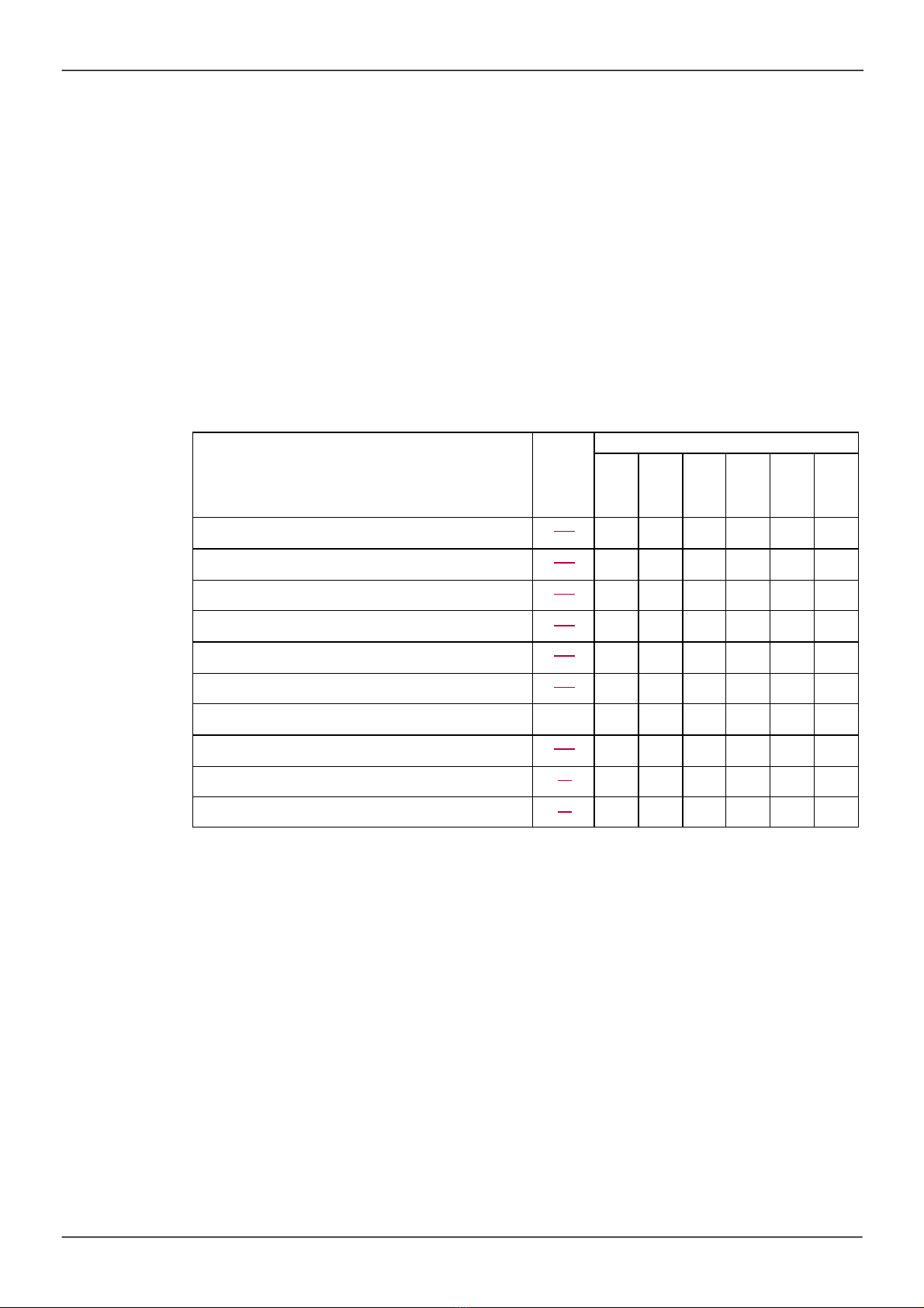
Motor control functions
Functions Page Applications
Hoist ing
Handlin g
Packin g
Textile s
Wood
Proce s s
V/f ratio 105
Sensorless flux vector control 105
2-point vector control 105
Open-loop synchronous motor 105
Output frequency up to 599 Hz 105
Motor overvoltage limiting 120
DC bus connection (see Installation manual)
-
Motor fluxing using a logic input 189
Sw itching frequency of up to 16 kHz 94
Auto-tuning 87

Overview
20
Functions on speed references
Functions Page Applications
Hoist ing
Handlin g
Packin g
Textile s
Wood
Proce s s
Differential bipolar reference 129
Reference delinearization (magnifying glass effect) 131
Frequency control input 154
Reference sw itching 167
Reference summing 168
Reference subtraction 168
Reference multiplication 168
Adjustable profile ramp 170
Jog operation 178
Preset speeds 180
+ speed / - speed using single action pushbuttons
(1 step)
184
+ speed / - speed using double action pushbuttons
(2 steps)
184
+/- speed around a reference 187
Save reference 188
Overview
21
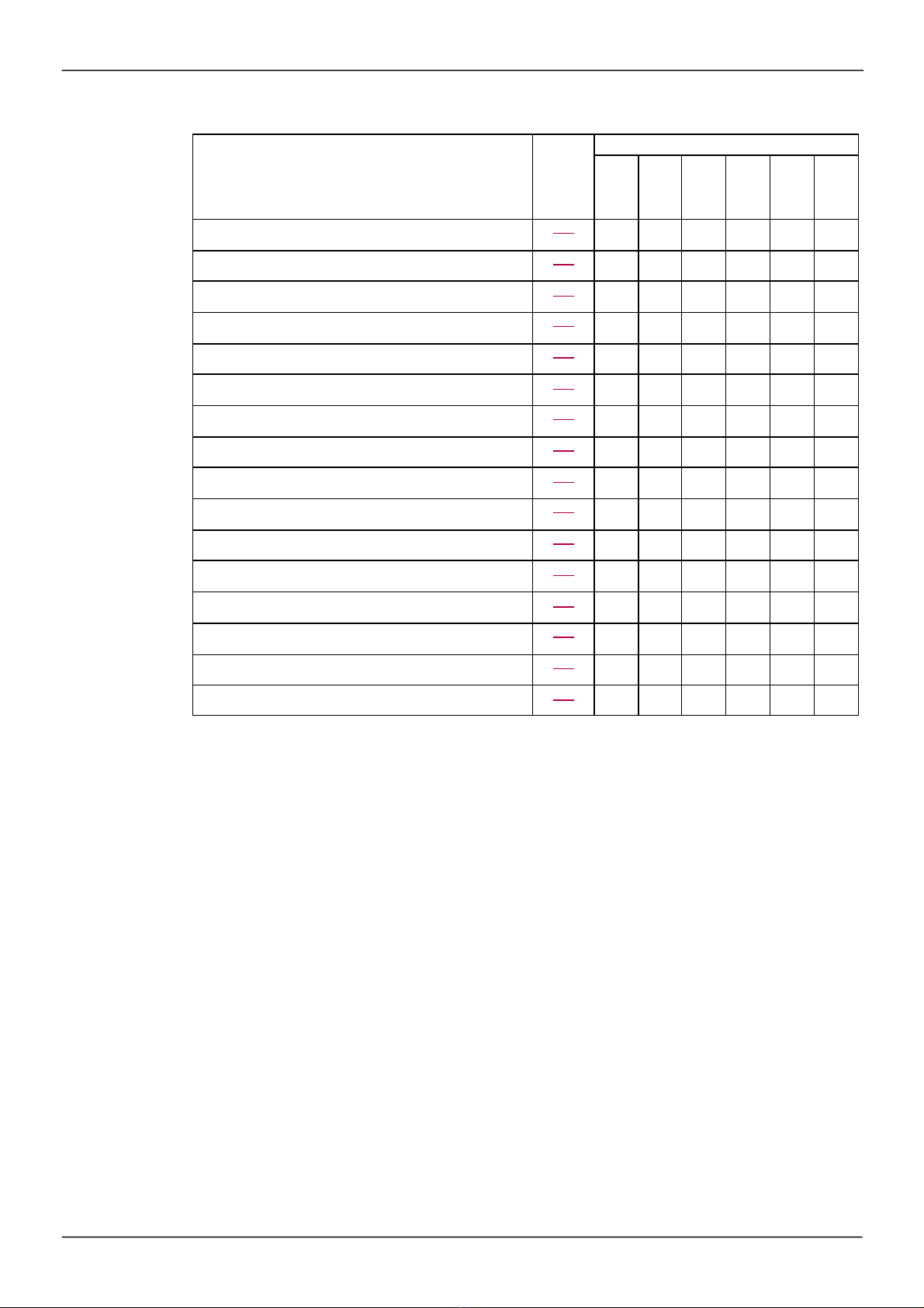
Application-Specific functions
Functions Page Applications
Hoist ing
Handlin g
Packin g
Textile s
Wood
Proce s s
Fast stop 173
Brake control 191
Load measurement 199
High-speed hoisting 201
Rope slack 204
PID regulator 206
Motor/generator torque limit 215
Load sharing 122
Line contactor control 220
Output contactor control 223
Positioning by limit sw itches or sensors 224
Stop at distance calculated after deceleration limit sw itch 226
Parameter sw itching 229
Motor or configuration switching 232
Traverse control 237
Stop configuration 173

Overview
22
Safety functions/Fault management
Functions Page Applications
Hoist ing
Handlin g
Packin g
Textile s
Wood
Proce s s
Safe Torque Off (STO) (Safety function, see dedicated
document)
-
Deferred stop on thermal alarm 258
Alarm handling 145
Fault management 250
IGBT tests 260
Catch a spinning load 253
Motor protection w ith PTC probes 250
Undervoltage management 259
4-20 mA loss 260
Uncontrolled output cut (output phase loss) 256
Automatic restart 252
Use of the "Pulse input" input to measure the speed of
rotation of the motor
265
Load variation detection 267
Underload detection 270
Overload detection 272
Safety Integrated functions (see related documents page 12)
This manual suits for next models
12
Table of contents
Other BLEMO Inverter manuals


