4
Aesculap®
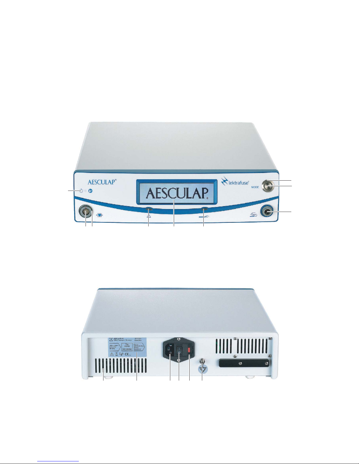
Lektrafuse HF generator GN200
ŹInspect the accessories regularly: Electrode cables and endoscopic
accessories, in particular, must be checked for possible damage to the
insulation.
ŹKeep the instructions for use accessible for the user.
ŹAlways adhere to applicable standards.
1.1 Safe for use in conformance with IEC regulations
The operating environment
ŹEnsure that the device does not come in direct contact with the patient
or in the sterile area respectively.
ŹEnsure that the user does not come into direct contact with the patient
and HF generator at the same time.
Patient safety
DANGER
Risk of death by electric shock!
ŹDo not open the product.
ŹOnly ever connect the product to power mains
with equipment grounding conductor.
WARNING
Risk of injury from ignition or explosion of flam-
mable gases! Sparks may occur when using the HF
generator as directed.
ŹDo not use the device in explosion-hazard zones.
ŹWhen operating in the head or thoracic region,
avoid using combustible anesthetics and accel-
erating gases (e.g. nitrous oxide or oxygen) or,
when using such substances, ensure they are
extracted from the region of operation.
ŹIf possible, use incombustible cleaning and dis-
infecting agents.
ŹIf combustible cleaning and disinfecting agents
or solvents have to be used: Verify that such
agents have evaporated prior to commencing HF
surgery.
ŹBe sure that no inflammable liquids accumulate
under the patient’s body or in body cavities (e.g.
the vagina). Before using the HF generator, wipe
up all fluids.
ŹEnsure the absence of any endogenous, combus-
tible gases.
ŹCheck that oxygen-soaked materials (e.g.
absorbent cotton or mull) are kept at a safe dis-
tance from the HF field, so that they cannot
ignite.
CAUTION
Risk of interference with other devices!
HF generators create potentially harmful magnetic
fields during normal use.
ŹBe sure that no electronic devices that could be
damaged by an electromagnetic field are set up
in the vicinity of the HF generator.
CAUTION
Restriction to view and/or side-effects due to the
development of steam/smoke during HF surgery!
ŹIf necessary, use smoke suction.
DANGER
Danger to life from inadequate preparation or
operational errors in the HF generator!
ŹBe sure that the HF generator is in perfect
working order.
ŹEnsure that neither the foot switch nor the hand
switch has been penetrated by conductive fluids
(e.g. blood, amniotic fluid).
ŹEnsure there is no short circuit in the foot or
hand switch cables.
DANGER
Risk of burns suffered by the patient due to inad-
vertent activation of the HF generator!
ŹSwitch off the HF generator immediately using
the power OFF/ON switch in the event that it is
activated accidentally.
ŹAlways exercise particular care when operating
the foot switch.
DANGER
Risk of injury to the patient due to an unintended
rise of the HF output voltage due to a fault in the
HF generator!
ŹStop using the HF surgical device as soon as it
shows even the slightest anomaly.
WARNING
Risk of injury to patients/users due to defective
power cord or missing protective ground connec-
tions!
ŹCheck the mains power cord/protective ground
connections.
WARNING
Danger of injuries due to muscle contraction,
caused by stimulation of the nerves and muscles!
ŹWork with particular care on sensitive struc-
tures.