Blockaudio Line & Power Block User manual


2
CONTENTS
PREFACE..................................................................................................................................................................3
IMPORTANT SAFETY INSTRUCTIONS ......................................................................................................................4
TRANSPORT ............................................................................................................................................................6
UNPACKING ............................................................................................................................................................6
PACKAGE CONTENT ................................................................................................................................................6
FRONT PANELS FEATURES ......................................................................................................................................7
BACK PANELS FEATURES.........................................................................................................................................8
BLOCK REMOTE ......................................................................................................................................................9
Functions ............................................................................................................................................................9
Pairing / Unpairing..............................................................................................................................................9
Battery Replacement..........................................................................................................................................9
DISPLAY CONTENT ............................................................................................................................................... 10
Content FULL ................................................................................................................................................... 10
Content SMART ............................................................................................................................................... 10
INSTALLATION...................................................................................................................................................... 11
Placement........................................................................................................................................................ 11
Adjusting feet .................................................................................................................................................. 11
Connecting the DC Supply and Control cables ................................................................................................ 11
Connecting the Line Input / Output Cables..................................................................................................... 11
Connecting Turntable (Phono Input)............................................................................................................... 11
System Remote Control (REM)........................................................................................................................ 12
Connecting AC mains Cable............................................................................................................................. 12
OPERATION.......................................................................................................................................................... 13
Turning On/Off ................................................................................................................................................ 13
Power Supply................................................................................................................................................... 13
Select Input...................................................................................................................................................... 13
Volume Control................................................................................................................................................ 13
Mute ................................................................................................................................................................ 13
Setup Menu ..................................................................................................................................................... 13
GND LIFT switches ........................................................................................................................................... 13
SETTINGS ............................................................................................................................................................. 14
GENERAL CONTROL / NAVIGATION................................................................................................................. 14
SETUP MENU Base-Level ................................................................................................................................. 14
SETTINGS Menu............................................................................................................................................... 15
ADVANCED SETTING Menu ............................................................................................................................. 15
INPUT SETUP Menu ......................................................................................................................................... 16
DISPLAY SETUP Menu ...................................................................................................................................... 18
VOLUME CONTROL SETUP Menu .................................................................................................................... 19
SURFACE CLEANING............................................................................................................................................. 20
WARRANTY .......................................................................................................................................................... 20
TROUBLESHOOTING ............................................................................................................................................ 21
SPECIFICATIONS................................................................................................................................................... 22
NOTES .................................................................................................................................................................. 22

3
PREFACE
The BLOCKAUDIO team congratulates you on your purchase of this device.
But before you start listening to your new LINE & POWER BLOCK, please read this
manual carefully so you are able to use and enjoy all functions of this unique
equipment without drawback on music quality.

4
IMPORTANT SAFETY INSTRUCTIONS
READ ALL INSTRUCTIONS: All the safety and operating instructions of your Block Audio device should be read
before power is applied to the equipment.
RETAIN THIS OWNER'S MANUAL: This safety and operating instructions should be retained for future reference.
HEED WARNINGS: All warnings on the unit and in the operating instructions should be adhered to.
FOLLOW INSTRUCTIONS: All operating and use instructions should be followed.
CLEANING: Unplug the unit from the wall outlet before cleaning.
GROUNDING: Do not defeat the safety purpose of the grounding-type plug. A grounding-type plug has two
blades and a third grounding prong. The third prong is provided for your safety. If the provided plug does not
fit into your outlet, consult an electrician for replacement of the obsolete outlet.
MAINS CABLES: Ensure that the mains cables (power supply cables) are not damaged. Never use the device if
the mains cable is damaged. Protect the mains cables from being walked on or pinched particularly at plugs,
convenience receptacles and the point where they exit from the apparatus.
LIGHTNING: Unplug this apparatus during lightning storms or when unused for long periods of time.
REPAIR: Any repairs or adjustment may only be performed by qualified personnel. The warranty will become
void if the user attempts to open and repair the apparatus. Improper intervention may interfere with the
electrical safety of the unit.
The manufacture assumes no liability for any accidents suffered by the user if the unit has been opened.
SERVICING: There are no user serviceable components inside this product. Servicing is required when the
apparatus has been damaged in any way, such as if the power-supply cord or plug is damaged, liquid has been
spilled inside the appliance or it has been exposed to moisture, the appliance does not operate normally, or
has been dropped.
To reduce the risk of fire or electric shock, DO NOT expose this apparatus to rain or moisture.
Never push anything into holes or slots in the case - this could result in an electric shock and could
cause damage of the set.
DO NOT connect any grounds (Input/Output) together, or to the chassis.
DO NOT connect the input of this preamplifier to a power amplifiers output.
5

6
TRANSPORT
Please transport the product only in the included package. Always use the provided foamed foil protection to
prevent scratches on the housing.
Please allow the equipment to adapt to the climatic conditions in your listening room before you switch on the
unit for the first time after transport.
UNPACKING
All Block Audio shipping boxes have been specially designed to protect their contents and special care has been
taken to prevent damage under normal shipping conditions. Mishandling should be evident upon inspection of
the shipping box.
We strongly recommend that you keep all original packaging in order to protect your components from damage
should you later wish to store or ship them.
PACKAGE CONTENT
Enclosed you will find the following items:
✓The Control Unit LINE BLOCK
✓The Supply Unit POWER BLOCK
✓The Owner’s Manual (that you are currently reading)
✓3 Detachable IEC Power Cords (with V-Lock)
✓2 Multi-pin “DC VOLT. INPUT / OUTPUT”Cables
✓Multi-pin “SUPPLY / CONTROL” Cable
✓2 “REM”Cables (System Remote Control)
✓Block Remote Unit
✓One small bubble level
✓Cotton gloves
✓Dispatch Form & Final Test Certificate

7
FRONT PANELS FEATURES
Rotary/Push Button: Turn this knob to adjust the volume level. Also used to put the Line Block into and out of
the Standby mode, for Input selection and Setup Menu navigation.
Display: Displays the selected input and the main volume level, as well as the settings menus.
IR Receiver: The IR receiver receives commands from the included remote control.
Light Sensor: This sensor receives ambient light to automatically dim Display and Status LED.
Status LED: Shows current operation mode:
•Steady light indicates - White: Battery operation, Orange: AC Mains operation (Battery Off)
•Red illuminates dimly: Standby mode
•Flashes during battery operation: Battery status Weak
•Flashes Orange: Battery Charging
•Flashes Red: Error
Adjustable feet: For accurate setup of horizontal position. Only front two feet are adjustable! See INSTALLATION
section for details.
PHONES: Headphones Output –3 pole XLR receptacle and 6.35 mm / ¼" stereo jack.
Inserting a headphone jack into this socket automatically switches off the outputs and turns off the Mono
Blocks. Other options are in the Setup Menu.
Status LED
Adjustable feet
Rotary/Push Button
Display
IR Receiver & Light Sensor

8
BACK PANELS FEATURES
RCA INPUTS: Unbalanced (single-ended) Input Connectors, white for left channel, red for right.
XLR INPUTS: Balanced (symmetrical) Input Connectors.
PHONO INPUT: Phono Input Connectors, white for left channel, red for right. and Phono/Chassis Ground Conn.
DC VOLT. INPUT: Power Supply Input Connector.
OUTPUTS I / II (“I” and “II” are identical):
RCA OUT: Unbalanced (single-ended) Output Connectors, white for left channel, red for right.
XLR OUT: Balanced (symmetrical) Output Connectors.
DC VOLT. OUTPUT: Power Supply Output Connectors.
SUPPLY / CONTROL: Control Interface and Power Supply for none-audio circuits.
AC MAINS INPUT: Mains supply inputs / 15 A power socket with V-Lock notch. Marking of the AC mains version.
REM LEFT / RIGHT: RJ45 connectors for system remote control.
GND LIFT / NORMAL: Ground lift switches. See OPERATION section for details.
9
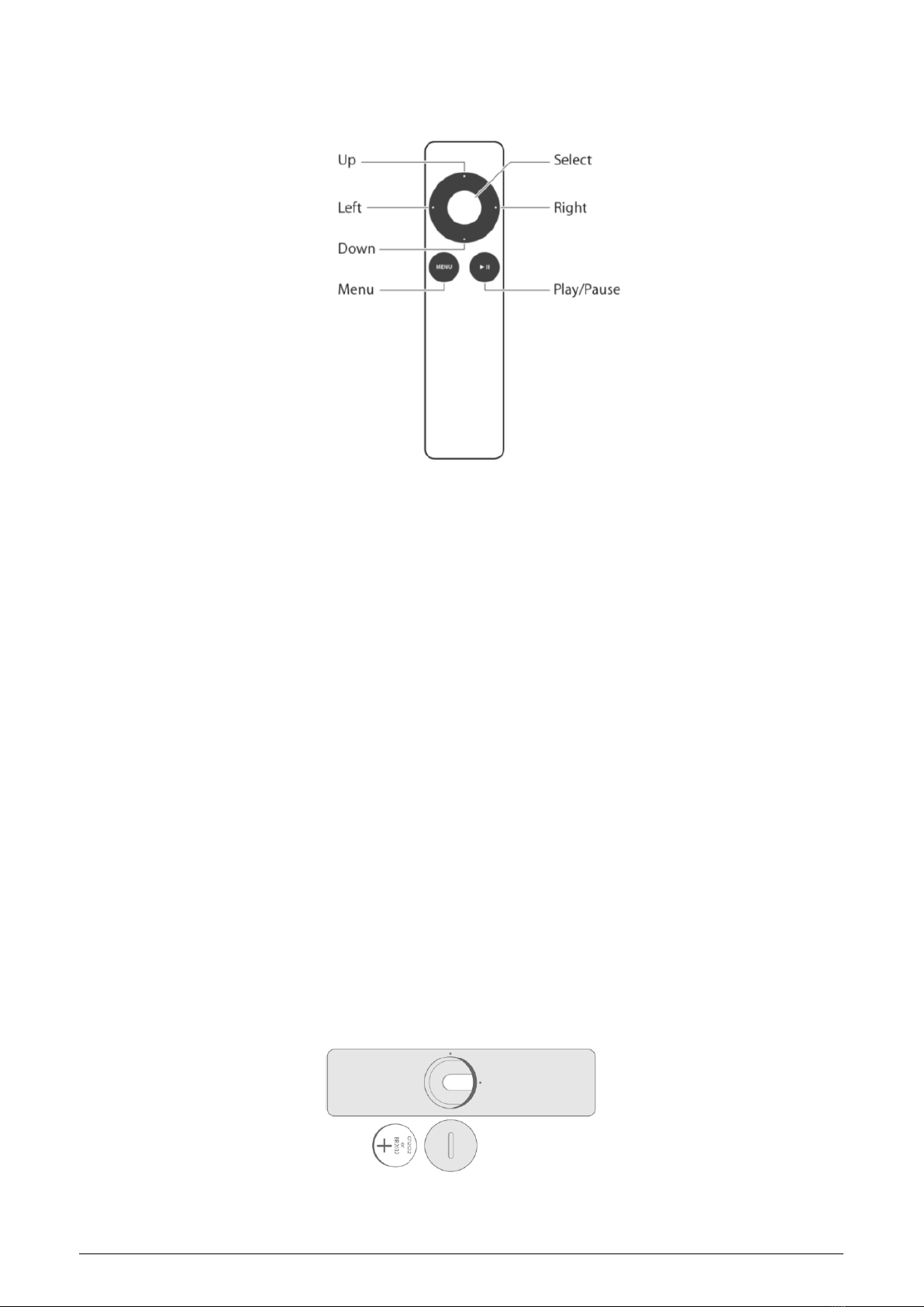
BLOCK REMOTE
Functions
UP/DOWN: Press these buttons to adjust the volume level. Use also to move the cursor, or to change values in
the Settings.
LEFT/RIGHT: Press these buttons to select the desired input. Use also to move the cursor, or to change values
in the Settings.
SELECT: This button can be used to put the Line Block, or system into and out of the Standby mode. Use also to
select/enter menu item in the Settings.
MENU: Press this button to display and escape the Setup Menu.
PLAY/PAUSE: This button allows you to mute and unmute the audio signal.
Pairing / Unpairing
Open Setup Menu, choose SETTINGS > ADVANCED > PAIR REMOTE: Instructions for the Pair / Unpair of the
Block Remote with the Line Block will be displayed.
Battery Replacement
•Find the battery component on the back of your Remote.
•Use a coin to turn the battery door counterclockwise until the door opens.
•Remove the old battery.
•With the positive side facing up toward you, put in the new CR2032 or BR2032 lithium 3V coin battery
(available at most electronic and drug stores).

10
DISPLAY CONTENT
Content FULL
Content SMART
Supply Mode /
Battery Status
Volume Level
System Balance
Output Phase
Selected
Input / Source
Status-Line for Mono Block:
Power transistors temperature
and Operation Mode
Subsonic Filter Symbol
Headphones Symbol
Mute Symbol
Input Gain Offset
Volume Level
Selected Input / Source
(Customized Input Name)
Volume Bar
Temporary message while
system turns On/Off

11
INSTALLATION
WARNING:
•Be sure to install it in a safe place from which it cannot fall or tip over.
•Do not connect loudspeaker wires or other high voltage sources to the inputs.
•Do not short-circuit the outputs.
•Do not allow the chassis to touch any metal parts, such as the frame of an equipment rack. This might
create a parallel ground path that could degrade the sound of your system.
Placement
The unpacked devices can be placed one by one on the shelves of a stable rack eider side by side, or can be
laid directly over each other: Line Block ON Power Block.
Install the Preamplifier chassis as close as possible to associated audio components to keep interconnecting
cables as short as possible.
Adjusting feet
The Line & Power Blocks are equipped with adjustable feet. After placing the units to the desired place, it is
possible to precisely adjust the horizontal position by rotating the front feet. This is especially important at
Power Block, because there is hanging transformer and should not have nothing to touch. A supportive bubble
level is enclosed.
Connecting the DC Supply and Control cables
DC Volt. Connectors: These connectors provide DC power from the Power Block chassis to the Line Block
chassis. Use the two supplied Multi-pin “DC VOLT. INPUT/OUTPUT” cables to connect Left / Right DC Volt.
Output to the Left / Right DC. Volt Input.
Using the supplied Multi-pin “SUPPLY / CONTROL” cable, connect the Power Block’s SUPPLY / CONTROL
connector to the Line Block’s SUPPLY / CONTROL connector.
The upper position of the connectors is indicated by the triangle () for easier orientation.
Connecting the Line Input / Output Cables
Connect the left channel output of a source to the desired left channel input number of the Line Block unit and
do the same for right channel.
You can use single ended RCA or balanced XLR cable for the connection.
Connect the left channel output of the Line Block unit to the left channel input of the power amplifier or to the
left monoblock. Do the same for right channel.
You can use single ended RCA or balanced XLR cable for the connections.
For the best sound performance, we recommend to use a balanced XLR cables, coming from the balanced
outputs on the source device to your Line Block and for connection to the Power Amplifier as well.
Note: To release the XLR connectors press on the release button next to the XLR socket, and pull the XLR plug
out at the same time. Do not pull on the cable, only on the plug.
Connecting Turntable (Phono Input)
Connect the twin RCA cable from your turntable to the Phono input, white for left channel, red for right.
Turntables normally includes a single wire earth lead. Use the Chassis Ground connector to connect this lead.
Unscrew the terminal to expose the hole, which will accept the lead. After insertion, tighten the terminal to
secure the lead.
Select your phono cartridge system (MC/MM) and other appropriate options in the Phono settings menu.

12
System Remote Control (REM)
The Line Block is equipped as standard with an RJ45 plug for system remote control.
If you own the Block Audio’s Mono Block, using the two supplied “REM” Cables, connect the REM Left and REM
Right to the left and right Mono Block.
Connecting AC mains Cable
If everything is connected, plug all three mains cables from a wall outlet or Power distributor to the AC Mains
Input sockets.
Appropriate AC mains version (115 V/60 Hz or 230 V/50 Hz) is factory pre-configured and is marked on the back
panel close to the AC mains sockets.
The device connector of enclosed mains cord is equipped with V-Lock system. This may prevent accidental
disconnection. To release the device mains connector, press on the yellow release button and pull the plug out
at the same time.
For best performance, try to route the power cord away from signal cables.

13
OPERATION
WARNING:
•DO NOT remove, or connect any cable while the preamplifier is running. Doing so risks damage to your
loudspeakers or the amplifier.
Turning On/Off
Press and hold the Rotary/Push Button or Select Button on Block Remote longer than two seconds to switch
the preamplifier on or off.
If the system remote control (REM cable) is applied, the whole system including Mono Block’s will in few
seconds turn into normal operation. The switch-on phase is indicated by the word "WAIT ..." in the display
status line. Other system On/Off options are in the Setup Menu.
Power Supply
The status LED on the Power Block shows current operation mode:
•Steady light White: Battery operation
•Steady light Orange: AC Mains operation (Battery Off)
•Steady light dimly Red: Standby mode
•Flashes White: Battery status Weak
•Flashes Orange: Battery Charging
•Flashes Red: Error
The supply mode can be selected in the Setup Menu. Battery Charging will be automatically activated when
the battery gets empty during operation, or the device is switched to Standby, or AC Mains operation. Charging
the battery may also be enforced in the Setup Menu.
Note: If the device is not going to be used for a long time, the batteries must be fully charged at least every six
months to maintain their service life.
Select Input
By short clicks on the Rotary / Push Button, or Left / Right button on the Block Remote, you can select the
desired input / signal source. The Input optional settings are possible in the Input Setup Menu.
Volume Control
Start playback of the selected source and after it adjust carefully the volume to the desired level by turning the
Rotary Button on the LINE BLOCK, or pushing Up / Down buttons on the Block Remote. The optional settings
are possible in the Volume Control Setup Menu.
Mute
Press PLAY/PAUSE button on the Block Remote to mute and unmute the audio signal of the Outputs. The Mute
Symbol blinks when the sound is muted. The Mute volume level can be determined in the Volume Control
Setup Menu.
Setup Menu
Press the Rotary / Push Button longer than two seconds, or press Menu button on the Block Remote to display
the Setup Menu and press again to exit.
GND LIFT switches
The ground lift switches, located on the back panel of the Power Block, can eliminate unwanted hum and buzz
(50/100 Hz) by interrupting the ground loops between two devices. Ideally only the source device remains
grounded and on the preamplifier and power amps. are the ground switches set to GND LIFT. You can try also
other combinations and then leave on the set up with the best result.
14
SETTINGS
This section explains the use of the setup menus on your LINE BLOCK, which allow you to customize and
configure the unit.
GENERAL CONTROL / NAVIGATION
Press & hold the Rotary/Push Button longer than two seconds, or press Menu Button on Block Remote to show
the Setup Menu on the display.
When the Setup Menu is active, use the Rotary Button, or Up/Down/Left/Right Buttons on Block Remote to
navigate, move the cursor through menu and to adjust parameters.
The Rotary/Push Button, or Select Button on Block Remote use to select and deselect options.
After selection of the DEFAULT option in the current menu, the default values will be returned.
After selection of the SAVE option in the current menu, the changes will be saved.
After selection of the CANCEL option in the current menu, the menu will move back a level in the menu
structure without changes saving.
After press Menu Button on Block Remote again will Setup Menu exit without changes saving.
After press & hold the Rotary/Push Button, or Select Button on Block Remote longer than two seconds, the
changes will be saved and the Setup Menu exits.
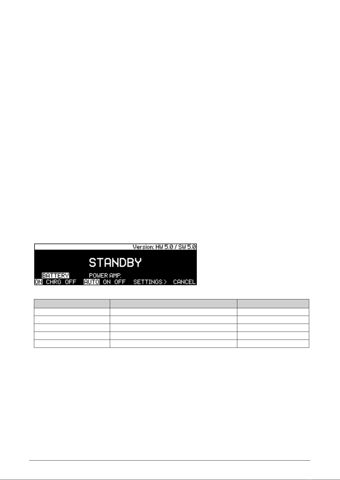
SETUP MENU Base-Level
Move the cursor to the desired position and then choose an option according the table below via Rotary/Push
Button, or via Select Button on the Block Remote.
STANDBY: After the selection, the Preamp / System switches to the Standby state.
BATTERY: This option lets you change the power supply mode:
•ON: Battery operation
•CHRG: Battery charging
•OFF: AC Mains operation
POWER AMP. / OUTPUT: This option lets you control the Mono Block units and the Line Block outputs:
•AUTO: The Mono Block units and the Line Block outputs will switch off/on after plug/unplug the Phones.
•ON: The Mono Block units and the Line Block outputs will be enforced to On and remain in this state.
•OFF: The Mono Block units and the Line Block outputs will be enforced to Off and remain in this state.
1) Appears only when Block Audio Mono Blocks are installed in the system.
SETUP Menu
OPTIONS
DEFAULT
STANDBY
STANDBY after Enter, or 5 sec. countdown
STANDBY after 5 sec.
BATTERY
ON / CHARGE / OFF
ON
POWER AMP.1) / OUTPUT
AUTO / ON / OFF
AUTO
SETTINGS >
Moves to the SETTINGS Menu
None
CANCEL
Exit the Setup Menu
None
15
SETTINGS Menu
Move the cursor to the desired position, select and then adjust value/option according the table below.
SETUP Menu
STANDBY
BATTERY
POWER AMP…
SETTINGS >
CANCEL
SETTINGS
OPTIONS
DEFAULT
CLASS 1)
A-ECO / A / ECO
A-ECO
BALANCE
Right -20 dB to Left -20dB
L = R
PHASE
L/R 0° / Left 180° / Right 180° / L/R 180°
L/R 0°
AUTO STANDBY
OFF / 0.5 h / 1 h / 3 h
OFF
ADVANCED >
Moves to the ADVANCED SETTING Menu
None
CLASS 1): This option lets you control the operation mode of the Mono Block. See Mono Block Owner’s Manual
for more details.
BALANCE: This setting lets you adjust Left-to-Right channel balance
PHASE: This setting lets you change the phase between the Input and Output audio signal.
AUTO STANDBY: This setting lets you adjust the timer that the preamplifier/system turns off during inactivity.
(no audio signal, and no user control input).
ADVANCED SETTING Menu
Move the cursor to the desired position and select option according the table below.
SETUP Menu
STANDBY
BATTERY
POWER AMP…
SETTINGS >
CANCEL
SETTINGS
CLASS
BALANCE
PHASE
AUTO STANDBY
ADVANCED >
ADVANCED
OPTIONS
DEFAULT
INPUTS >
Moves to INPUTS Menu
None
DISPLAY >
Moves to DISPLAY Menu
None
VOLUME >
Moves to VOLUME Menu
None
PAIR REMOTE
PAIR / UNPAIR REMOTE
PAIR REMOTE
FACTORY RESET
Factory Reset menu
None
PAIR REMOTE: This option lets you Pair / Unpair your Block Remote with the Line Block. After the selection, the
instructions for Pair / Unpair will be displayed.
FACTORY RESET: This option lets you return all default values. After the selection, the Factory Reset menu will
appear.
1) Appears only when Block Audio Mono Blocks are installed in the system.

16
INPUT SETUP Menu
The following settings are available for all Inputs.
Move the cursor to the desired input, select one of the next column, and then choose value/option according
the table below.
SETUP Menu
STANDBY
BATTERY
POWER AMP...
SETTINGS >
CANCEL
SETTINGS
CLASS
BALANCE
PHASE
AUTO STANDBY
ADVANCED >
ADVANCED
INPUTS >
DISPLAY >
VOLUME >
PAIR REMOTE
FACTORY RESET
INPUTS
RCA 1
RCA 2
RCA 3
RCA 4
RCA 5
XLR 1
XLR 2
XLR 3
XLR 4
PHONO
SET INPUT X
OPTIONS
DEFAULT
USED
□/ ■(ON / OFF)
□(ON)
OFFSET
0 dB to -15 dB (1 dB step)
0 dB
BYPASS
OFF / ON
OFF
SET INPUT PHONO
OPTIONS
DEFAULT
USED
□/ ■(ON / OFF)
□(ON)
>
Moves to PHONO Menu
None
USED: This option removes the selected input from the list of available inputs. The input will be skipped when
selecting the active input.
OFFSET: This setting lets you adjust all associated devices in your system to output at a similar volume level.
BYPASS: This mode allows users to optimally integrate the LINE BLOCK with AV systems. In Bypass mode, the
input signal by-passes the preamplifier section without any adjustment for volume.
17
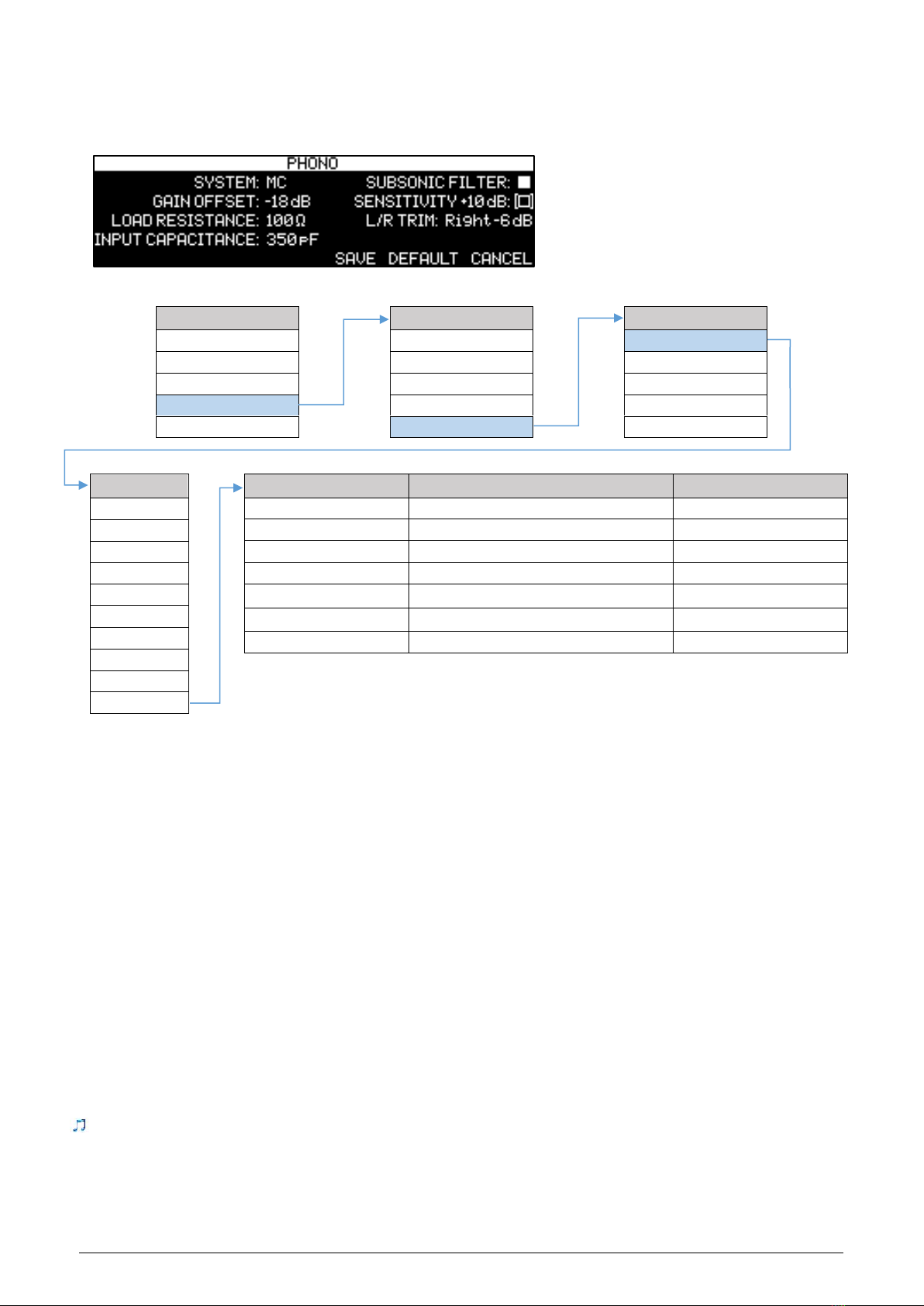
The following settings are available only for the Phono Input.
Move the cursor to the desired input, select the next column, and then choose value/option according the
table below.
SETUP Menu
STANDBY
BATTERY
POWER AMP...
SETTINGS >
CANCEL
SETTINGS
CLASS
BALANCE
PHASE
AUTO STANDBY
ADVANCED >
ADVANCED
INPUTS >
DISPLAY >
VOLUME >
PAIR REMOTE
FACTORY RESET
INPUTS
RCA 1
RCA 2
RCA 3
RCA 4
RCA 5
XLR 1
XLR 2
XLR 3
XLR 4
PHONO
SET PHONO
OPTIONS
DEFAULT
SYSTEM
MC / MM
MC
GAIN OFFSET
0 dB to -20 dB (1 dB step)
0 dB
LOAD RESISTANCE
MC: 10 Ω to 1 kΩ, MM: 47 kΩ / 1 kΩ
MC: 100 Ω, MM: 47 kΩ
INPUT CAPACITANCE
50 pF to 400 pF
MC: 50 pF, MM: 350 pF
SUBSONIC FILTER
■/ □(OFF / ON)
■(OFF)
SENSITIVITY +10dB *
■/ □(OFF / ON)
■(OFF)
L/R TRIM
0 dB to -6 dB (1 dB step)
L = R
SYSTEM: This setting lets you choose from two phono cartridge types preset settings. MC (Moving-Coil) and
MM (Moving-Magnet) presets include Gain, Load Resistance, Input Capacitance, L/R Trim.
GAIN OFFSET: This setting lets you adjust the phono input to a similar volume as all associated devices in your
system.
LOAD RESISTANCE: This setting offers a choice of resistive loading values for the Phono input:
•For MC: 10, 15, 30, 40, 50, 70, 100, 200, 300, 600 and 1000 Ω
•For MM: 1 kΩ, 47 kΩ
INPUT CAPACITANCE: This setting offers a choice of capacitive loading values for the Phono input:
•50, 100, 150, 200, 250, 300, 350, 400 pF
SUBSONIC FILTER: This setting lets you engage or disengage a 20 Hz high-pass filter for the Phono input,
allowing for a reduction of infrasonic interference.
SENSITIVITY +10dB *: This setting offers to increase the input sensitivity for very low-output cartridges.
L/R TRIM: This setting lets you compensate for subtle left-to-right channel imbalances in the phono playback
system.
We recommend initially setting the Load Resistance and Input Capacitance parameters to match your phono
cartridge manufacturer’s recommendations. Feel free to experiment with other values to fine-tune phono
performance to your preference.
* Not implemented yet
18
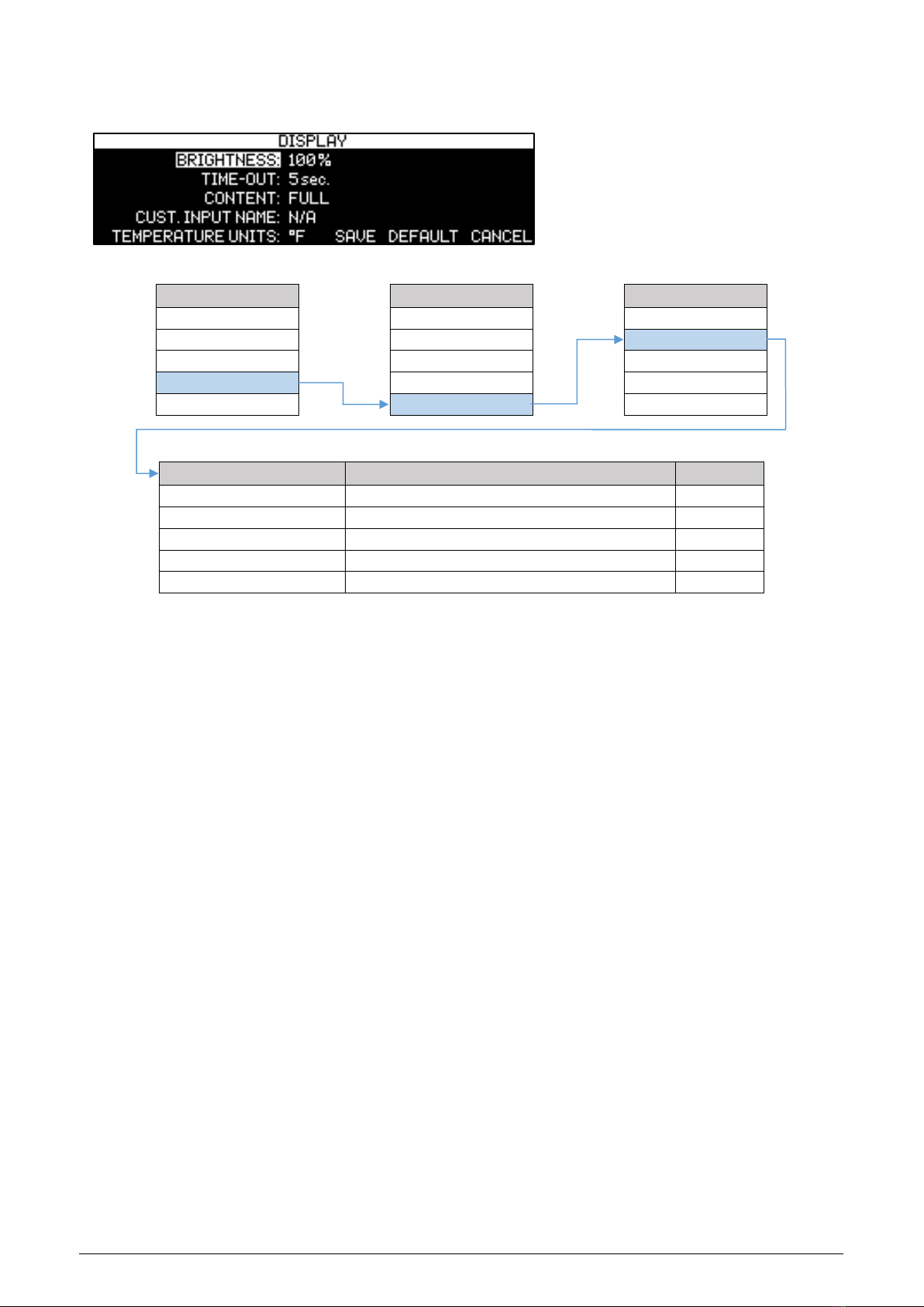
DISPLAY SETUP Menu
Move the cursor to the desired position, select and then adjust value/option according the table below.
SETUP Menu
STANDBY
BATTERY
POWER AMP…
SETTINGS >
CANCEL
SETTINGS
CLASS
BALANCE
PHASE
AUTO STANDBY
ADVANCED >
ADVANCED
INPUTS >
DISPLAY >
VOLUME >
PAIR REMOTE
FACTORY RESET
DISPLAY Menu
OPTIONS
DEFAULT
BRIGHTNESS
AUTO / 20 / 40 / 60 / 80 / 100 %
AUTO
TIME-OUT
OFF / 2 to 10 sec. / DISPLAY OFF
OFF
CONTENT
FULL / SMART
FULL
CUST. INPUT NAME
FULL: N/A, SMART: None, AUX, CD, SA-CD, …
N/A
TEMPERATURE UNITS 1)
°C / °F
°C
BRIGHTNESS: This setting lets you manually adjust the Display and status LED brightness. While AUTO option
chosen, the brightness will be adapted depending to ambient light.
TIME-OUT: This setting lets you choose how long the display remains lit after the last time a control is operated.
In OFF mode display remains on, in DISPLAY OFF mode display remains off also during volume control
operation.
CONTENT: This setting lets you choose the display mode:
•FULL: In this mode, the complete content of the display will be shown, see chapter DISPLAY for further
details.
•SMART: Only the most important information’s for usual usage will be shown, see chapter DISPLAY for
further details. The Input name can be customized for this display mode.
CUST. INPUT NAME: This option, while Smart content mode is chosen, offers you to rename the inputs by
preset labels or even to create your own names.
•Preset labels: AUX, CD, SA-CD, DVD-A, DVD, BLU-RAY, TUNER, TAPE, SAT, DAC, MP3, PC, TV, DAB.
•Own names: Use the Rotary Button on the LINE BLOCK to choose from the list of available characters and
press the Rotary Button to confirm each character.
TEMPERATURE UNITS 1): This setting lets you choose desired units for display of the power amplifier
temperature.
1) Appears only when Block Audio Mono Blocks are installed in the system.
19
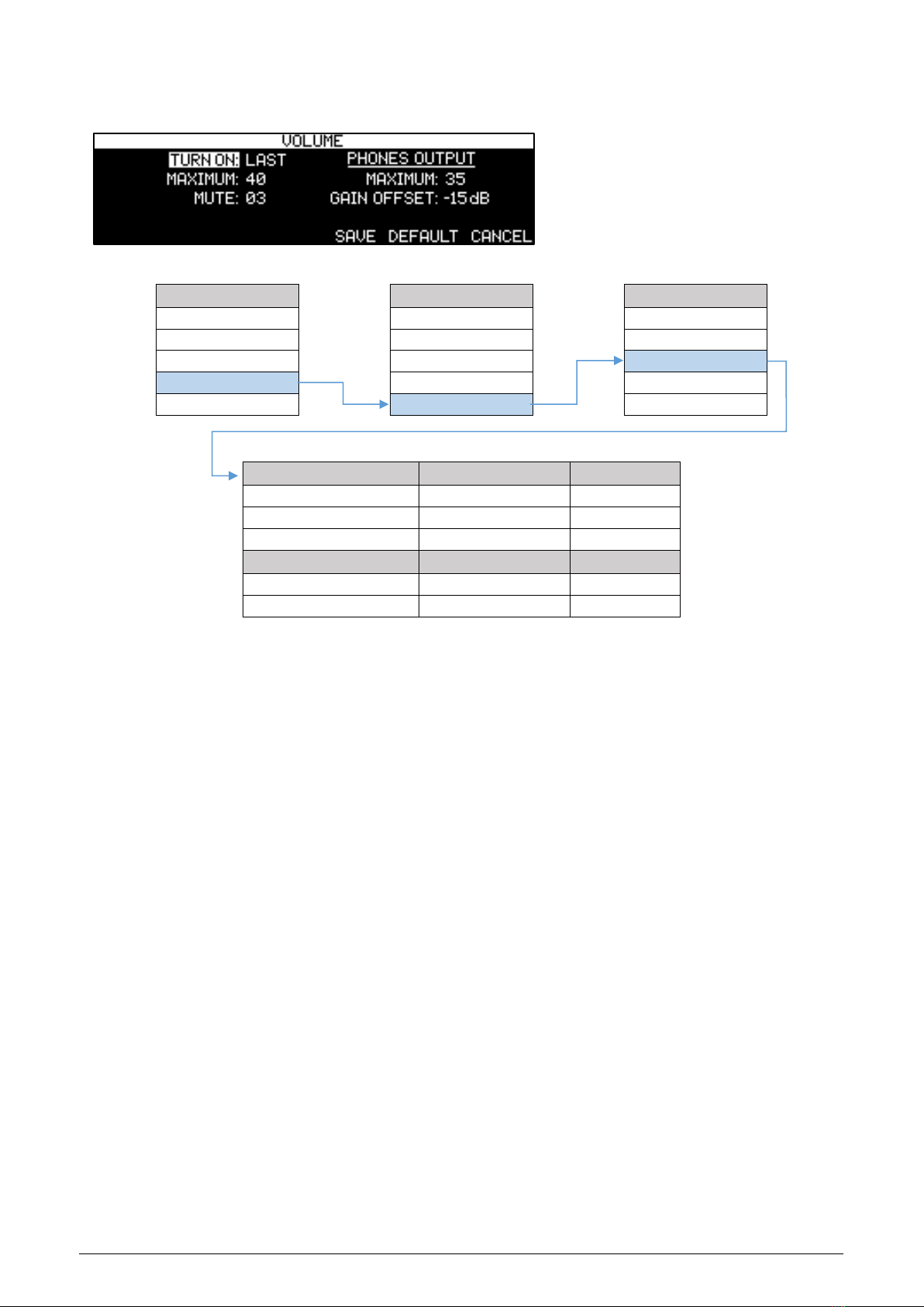
VOLUME CONTROL SETUP Menu
Move the cursor to the desired position, select and then adjust value/option according the table below.
SETUP Menu
STANDBY
BATTERY
POWER AMP…
SETTINGS >
CANCEL
SETTINGS
CLASS
BALANCE
PHASE
AUTO STANDBY
ADVANCED >
ADVANCED
INPUTS >
DISPLAY >
VOLUME >
PAIR REMOTE
FACTORY RESET
VOLUME Menu
OPTIONS
DEFAULT
TURN ON
LAST, 03 to 20
LAST
MAXIMUM
20 to 50
50
MUTE
00 to 05
00
PHONES OUTPUT
OPTIONS
DEFAULT
MAXIMUM
20 to 50
50
VOL. OFFSET
-15 dB to +15 dB
0 dB
TURN ON: This setting lets you set a line output volume level to which your Line Block will default every time
you turn it on. While LAST option chosen, the volume level setting from the previous time the unit was powered
down is retained.
CAUTION: Setting the TURN ON parameter to LAST can result in louder-than-expected power-up volume if the Line Block
was set to a high volume level setting when last powered down.
MAXIMUM: This setting lets you set a maximum line output volume level.
MUTE: This option lets you set the line output volume level that occurs when the PLAY/PAUSE button on the
Block Remote is engaged.
PHONES OUTPUT
MAXIMUM: This setting lets you set a maximum phones output volume level.
VOL. OFFSET: This option allows you to match the volume of your headphones with the speaker volume in the
system.

20
SURFACE CLEANING
The cabinet outside is coated with a special paint that is resistant to spotting. However, from time to time you
may wish to clean the surface of your Block Audio equipment to remove dust, or any material build up from
the atmosphere or from common use. Therefore, we recommend only gently clean the dust off, eventually
wiping the water moistening microfiber cleaning cloth while observing the following guidelines:
•As a safety precaution, always unplug the unit from the wall outlet before cleaning
•Always use a cloth that is soft and clean
•Never use abrasives or polishing compounds anywhere on the unit
•Never apply liquid directly to the surface of the unit
•Use the cloth dry or with mild surface cleaners of either liquid or foaming type
•Apply only small amounts of cleaner to the cloth
•DO NOT rub the surface but wipe clean only. Excessive rubbing may wear the coating or screen printed
text.
WARRANTY
All Block Audio products are warranted against defects in material and workmanship for a period of two years
from the date of purchase. (Longer warranty period is available and depends on local conditions provided by
sales partner of Block Audio).
The warranty is void if the product has been subject to misuse or negligence or modified, repaired or opened
by an unauthorized person, or the product was not operated in accordance with the instruction manual.
For the return transport to our premises, please use the original packaging. Transport damages are not covered
by this warranty, Repairs will be charged. We recommend to conclude on effecting transport insurance.
If you do not have the original packaging, please contact your Block Audio dealer for advice or information
about transport.
Basic repairs can be arranged by your local Block Audio dealer or distributor. Please apply your complaints on
your local seller side first to secure the comfortable and fast solution of your eventual needs.
Table of contents
Other Blockaudio Amplifier manuals

Popular Amplifier manuals by other brands


Teac
Teac AP-701 owner's manual

SKAR Audio
SKAR Audio RP-800.1D RP-1200.1D RP-2000.1D user manual

Listen Technologies
Listen Technologies External Microphone Control RS232 Protocol DCS... brochure

Kenwood
Kenwood KAC-819 Service manual

Pioneer
Pioneer A-209 operating instructions

Audio Analogue
Audio Analogue MAESTRO DUECENTO owner's manual


