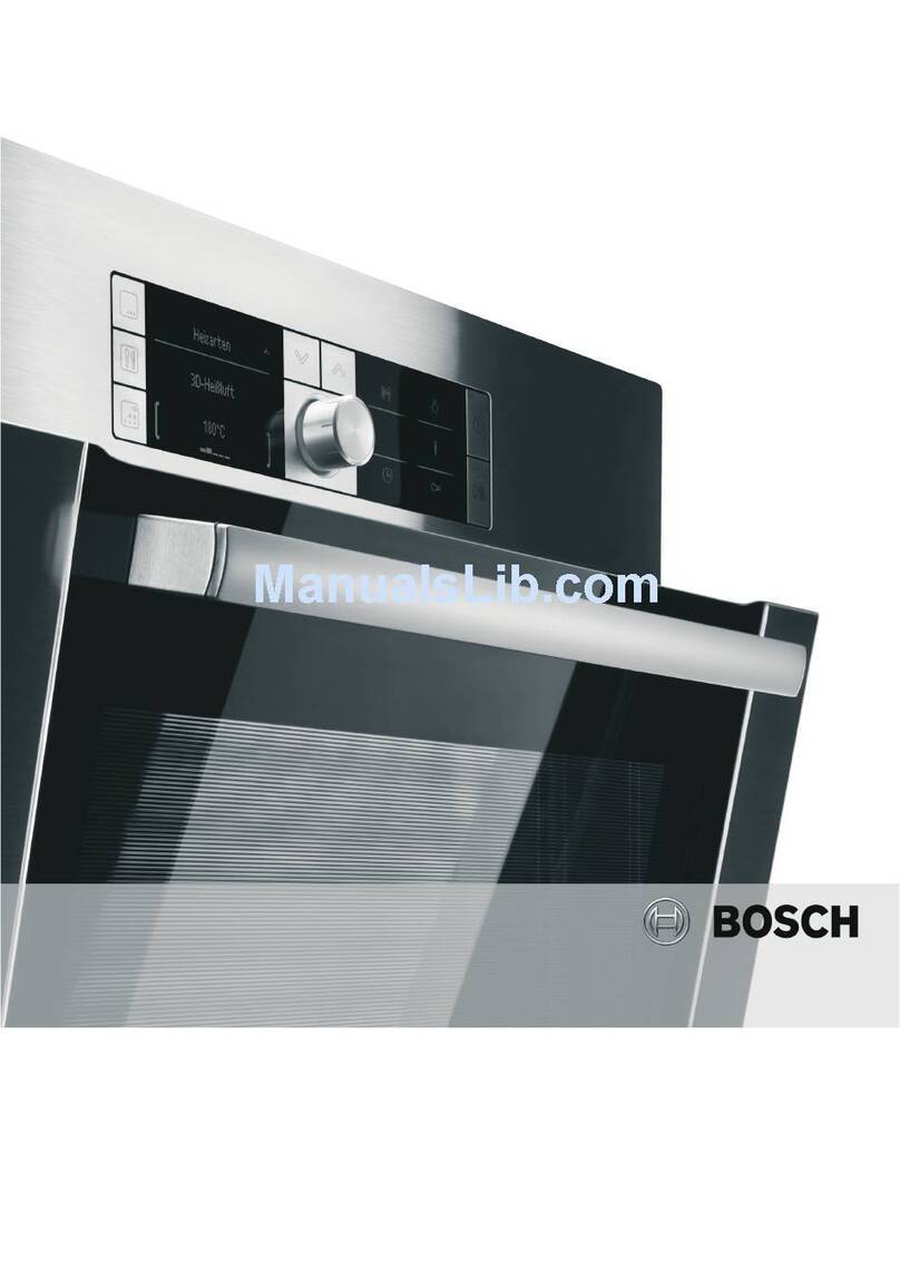
Blodgett Combi COS-5H User manual

BLODGETT COMBI
www.blodgett.com
44 Lakeside Avenue Burlington, Vermont 05401 USA elephone (800) 331Ć5842, (802) 860Ć3700 Fax: (802)864Ć0183
PN R10303 Rev K (4/09)
E 2009 - Blodgett Corporation
MIN
PSIN
COSĆ5HA
INSTALLATION AND OPERATION INSTRUCTIONS
FOR SHIPBOARD USE
FSCM 07695

MIN # XXXXXXXXXXXXXXXXXXXXX
SAFETY SUMMARY
he following are general safety precautions that are not related to any specific procedures
and therefore do not appear elsewhere in this publication. hese recommend precautions
that personnel must understand and apply during many phases of operation and mainteĆ
nance.
KEEP AWAY FROM LIVE CIRCUITS
Operating personnel must at all times observe all safety regulations. Do not replace comĆ
ponents or make adjustments inside the equipment with the high voltage supply turned
on. Under certain conditions, dangerous potentials may exist when the power control is
in the off position, due to the charge retained in capacitors. o avoid casualties, always reĆ
move power and discharge and ground a circuit before touching it.
DO NOT SERVICE OR ADJUST ALONE
Under no circumstances should any person reach into or enter the enclosure for the purĆ
pose of servicing or adjusting the equipment except in the presence of someone who is
capable of rendering aid.
RESUSCITATION
Personnel working with or near high voltages should be familiar with modern methods of
resuscitation.
he following appear in the text of this volume, and are repeated here for emphasis.
WARNING:
Before performing any mainteĆ
nance or replacing any component
on this unit, disconnect oven from
electrical source.

MIN # XXXXXXXXXXXXXXXXXXXXX
CHANGE RECORD
CHANGE NO DATE TITLE/BRIEF DESCRIPTION SIGNATURE OF
VALIDATING OFCR

MIN # XXXXXXXXXXXXXXXXXXXXX
LIST OF EFFECTIVE PAGES
Insert latest changed pages. Destroy superceded pages.
NOTE:The portion of the text affected by the changes is indicated by a vertical line in the
outer margins of the page. Changes to illustrations are indicated by miniature pointĆ
ing hands. Changes to diagrams are indicated by shaded areas.
Dates of issue for original and changed pages are:
Original MARCH 2002. . .
he total number of pages in this publication are: 54
consisting of the following:
PAGE NO CHANGE NO * PAGE NO CHANGE NO *
* Zero in this column indicates an original page

MIN # XXXXXXXXXXXXXXXXXXXXX
APPROVAL AND PROCUREMENT RECORD
APPROVAL DA A FOR: COSĆ5H
Electric Combination Oven
I LE OF MANUAL: echnical Manual, COSĆ5H
Electric Combination Oven
APPROVAL AU HORI Y: Defense General Supply Center
Letter Dated ?? ??? ??
CONTRACT NO NSN NO OF UNITS APL
REMARKS
DA E: 5 Mar 98
CER IFICA ION:
It is hereby certified that the technical manual provided under contract number XXXĆXXXĆ
XXĆXĆXXXX for COSĆ5H has been approved by the approval data shown above.
(Signed) _____________________________
im haler
( itle) Director of National Accountsą
Blodgett Combi
44 Lakeside Avenue
Burlington, V 05401
FSCM 07695

(Insert Classif of TMDER Here and At Bottom of Page) CLASSIFICATION:
NAVSEA (USER) TECHNICAL MANUAL DEFICIENCY/EVALUATION REPORT (TMDER)
(NAVSEA S0005-AA-GYD-030/TMMP & NAVSEAINST 4160 3)
Instructions: Insert classification at top and bottom of page. ead the following before completing this
form. Continue on 8½I x 11I paper if additional space is needed.
1. USE HIS REPOR O INDICA E DEFICIENCIES, USER REMARKS, AND RECOMMENDA IONS RELA ING O PUBLICA ION
2. BLOCKS MARKED WI H " * " ARE O BE FILLED IN BY HE CON RAC OR BEFORE PRIN ING.
3. FOR UNCLASSIFIED MDER'S FILL IN YOUR RE URN ADDRESS IN SPACE PROVIDED ON HE BACK. FOLD AND APE WHERE
INDICA ED AND MAIL. (SEE OPNAVINS 5510.1E FOR MAILING CLASSIFIED MDERS.)
4. FOR ADDI IONAL INFORMA ION, CALL AU OVON 360-4809-9084 OR COMMERCIAL 905-882-5064
1. NAVSEA NO. * 2. VOL.
PAR *
3. I LE *
4. REV DA E OR M CH.
DA E
5. SYS EM/EQUIPMEN 6. IDEN IFICA ION/NOMENCLA URE (MK/MOD/AN)
7. USERS EVALUA ION OF MANUAL (CHECK APP OP IATE BLOCKS)
A. EXCELLEN B. GOOD C. FAIR D. POOR E. COM PLE E F. INCOMPLE E
8. GENERAL COMMEN S
9. RECOMMENDED CHANGES O PUBLICA ION
PAGE
NO.
A.
PARA
GRAPH
B.
LINE
NO.
C.
FIG.
NO.
D.
ABLE
E.
F. RECOMMENDED CHANGES AND REASONS
10. ORIGINA OR AND WORK CEN ER (PRIN ) 11. ORIGINA OR'S RANK, RA E OR GRADE, AND I LE 12. DA E SIGNED
13. SIGNA URE OF WORK CEN ER HEAD 14. SIGNA URE OF DEPAR MEN OFFICER 15. AU OVON/COMM
NO.
16. SHIP HULL NO. AND/OR S A ION ADDRESS (DO NO ABBREVIA E)
17. HIS SPACE ONLY FOR NSDSA
A. CON ROL NO. B. COG ISEA C. DA E D. PRIORI Y E. RANSMI ED O
RECEIVED FORWARDED DUE
NAVSEA 9066/10 (REV 6 85) S/N 0116-LF-090-9651 CLASSIFICATION:
(REPLACES 4-84 EDITION & NAVSEA 4160/1-
DESTROY STOCK)

PLEASE CLOSE WITH TAPE - DO NOT STAPLE - THANK YOU
FOLD HERE
COMMANDING OFFICER
NAVAL SHIP WEAPON SYSTEMS ENGINEERING STATION
NAVAL SEA DATA SUPPORT ACTIVITY (CODE 5B00)
PORT HUENEME, CA 93043-5007
FOLD HERE

IMPORTANT
FOR YOUR SAFETY
Do not store or use gasoline or other flammable vapors or
liquids in the vicinity of this or any other appliance
WARNING: IMPROPER INSTALLATION, ADJUSTMENT,
ALTERATION, SERVICE OR MAINTENANCE CAN CAUSE
PROPERTY DAMAGE, INJURY OR DEATH READ THE INĆ
STALLATION, OPERATING AND MAINTENANCE INĆ
STRUCTIONS THOROUGHLY BEFORE INSTALLING OR
SERVICING THIS EQUIPMENT
The information contained in this manual is important for the proper
installation, use, and maintenance of this oven Adherence to these
procedures and instructions will result in satisfactory baking results
and long, trouble free service Please read this manual carefully and
retain it for future reference
Errors: Descriptive, typographic or pictorial errors are subject to correcĆ
tion Specifications are subject to change without notice

A PERSONAL WORD
FROM BLODGETT COMBI
Congratulations on your purchase of the BLODGE CombiĆOven/Steamer.
We firmly believe that your choice has been a wise one, and trust you will reĆ
ceive many years of excellent service from your new multiĆpurpose oven.
he CombiĆOven/Steamer concept offers completely new potential for cookĆ
ing which minimizes shrinkage, while maintaining food's essential vitamins
and valuable nutrients. In addition, you will find that cooking with the CombiĆ
Oven/Steamer will save time, labor and extensive cleaning of both the kitchen
and the appliance.
With the CombiĆOven/Steamer the quality, taste, consistency, and look of the
food are improved, thus endorsing the policy to which we've always adhered:
For Better Cooking!"
Once you've had a chance to use your multiĆpurpose oven, please tell us, your
dealer and colleagues about any creative and interesting applications you
have discovered; exchange ideas with other users. Be sure to advise us or
your dealer immediately should any mechanical or technical problems be enĆ
countered (...we're here to help!) and above all Enjoy Cooking the
BLODGE CombiĆOven/Steamer Way!

Your Service Agency's Address:
Model:
Serial Number:
Your oven was installed by:
Your oven's installation was checked by:

Introduction
2
The Blodgett CombiĆOven/Steamer
For quite some time, commercial cooking equipĆ
ment has remained more or less unchanged.
here are kettles, deck ovens, the good old range
with its legion of pots āand āmany āother āextra
āappliances. he result: time expenditure, excesĆ
sive manual work, and countless cleaning proĆ
cesses. he last āāāfew āāāyears āāhave āāpaved āāthe āāway āāfor
āa revolution in the equipment of restaurant and inĆ
stitutional kitchens.
he Blodgett CombiĆOven/Steamer offers a comĆ
pletely new method of cooking. With the Oven/
Steamer you have the choice of two cooking proĆ
cesses: Steam and Hot Air, either...
DSeparately
DCombined, or
DIn Sequence
And for easy operation you can choose from three
modes:
Steam Hot Air Combi
Steam &
Hot Air
In the Steam mode you can:
steam reheat reconstitute
stew thaw simmer
blanch preserve braise
poach
In the Hot Air mode you can
roast bake
grill gratinate
broil
In the Combination Steam and Hot Air mode you
can:
defrost roast rethermalize
reheat bake forced steaming
Not āāonly āāthat, āāyou āācan āāuse āātwo āāor āthree functions
in sequence during one cooking process. We call
this:
DcombiĆsteaming
DcombiĆroasting
DcombiĆbaking
he combination of circulating hot air and steam
in the space saving, high performance CombiĆ
Oven/Steamer leads to improvements in the folĆ
lowing areas:
Dincreased productivity in the kitchen
Da reduction in capital expenditures for multiple
equipment replacement
Da wider range of menu choices
Da simplified cleaning process
he work process is simplified since products are
prepared on or in steam table āpans āand trays.
Food can be cooked, stored, and transported with
āthe āsame āāpans. āSmall āamounts of product can be
processed efficiently; preĆcooked and conveĆ
nience foods can be reheated within minutes.
āMany frozen foods can be processed without preĆ
thawing. his flexibility in preparation reduces the
need for kettles and steam tables since there is no
need for large amounts of food to be kept warm for
long periods of time.
oday the improvement of food quality is more imĆ
portant than ever. Vegetables are cooked in the
Blodgett CombiĆOven/Steamer without water at
the optimal temperature of just under
212_F/100_C, maintaining valuable vitamins, minĆ
erals, nutrients and trace elements.āā Cooking meat
in the Combi results in less shrinkage and a firmer,
juicier product. he Blodgett CombiĆOven/SteamĆ
er is being used more and more for baking. Steam
and Hot āAir āmodes āmake āit āa āgeneral āpurpose bakĆ
ing appliance.

Introduction
3
Description of the CombiĆOven/Steamer
ABOUT THE OVEN/STEAMER
Blodgett CombiĆOven/Steamers are quality proĆ
duced using highĆgrade stainless steel with first
class workmanship.
he high performance fresh steam generator with
its control system makes it possible to enjoy all of
the advantages of a high quality steamer at the
flick of a switch. Fresh steam enters the oven cavĆ
ity without pressure and is circulated at high
speed. his process enables quick and gentle
cooking and ensures high quality food while proĆ
viding convenient working methods. he steam
generator is completely automatic and protected
from running dry.
he exhaust system is effective in all cooking
modes and results in better quality foods and no
flavor transfer. he fan, which is guarded against
accidental finger contact, is driven by a quiet and
powerful motor. he condenser draws out excess
steam from the appliance. Condensation and
waste water, which result during steaming and
cleaning, are continuously drained.
he use of high quality insulation impedes excesĆ
sive heat radiation and saves energy.
OVEN/STEAMER OPERATION
Ease of operation is guaranteed through the simĆ
ple arrangement of the controls. Graphic symbols
make the appliance easy for even inexperienced
kitchen staff to operate. Steam, Hot Air and Combi
modes can be selected with one switch. A fourth
function on the mode selection switch, the Cool
Down mode, allows the oven cavity to cool down
rapidly with the door opened or closed.
Cleaning is kept to a minimum. he interior is
sprayed with a selfĆacting cleaning solution which
interacts with steam to easily remove crusts and
stains. he oven is designed for easy care and is
welded water tight so that the internal cooking
cavity may be rinsed with a hose after the steam
cleaning process.
SPECIFICATIONS - COSĆ5HD/AB
Electrical
Specifications 440Ć480 VAC, 3 phase, 44 KW, 58 amps
Water Atmospheric Vented Drain
Water Pressure 40 PSI (276 kPa) minimum
50 PSI (345 kPa) maximum
Water Connection 3/4" NP Female

Introduction
4
Oven Features
Standard Features
1
2 23
7
8
4
5
6
5
6
Figure 1
1 Control Panel
2 Oven Doors
3 Rotating Door Latch
4 Base Section
5 Deliming Port
6 Deliming Handle
7 Optional Meat Probe
8 Door Drip Pan

Installation
5
General Installation Information
he purpose of the installation section of this
manual is to assist the designers and naval archiĆ
tects engineering the installation of a Blodgett
Combi COSĆ5HA Hatchable Combination Oven
into a new or existing ship.
Blodgett Combi has developed the COSĆ5HA to fit
in the same footprint as a Blodgett Mark V convecĆ
tion Oven. he COSĆ5HA Combination oven can
be used as a convection oven, steamer, or in a
Combi" mode in which pulsed steam is comĆ
bined with convection to provide faster cooking
and increase the moisture content of cooked
foods. Because of these features, the oven utilizes
water for generating steam. he Combi is a multiĆ
system cooking oven and is more complex than a
convectional oven. herefore, more attention has
to be paid to the installation process than that of
a convection oven.
he COSĆ5HA requires the following support sysĆ
tems:
DPower 440 VAC, 3 phase, 60 amp service
DWater Potable, 40 to 50 psi
DDrain Atmospheric vented drain,
1" minimum diameter
DHood Air venting required for steam
removal
HE INS ALLA ION INS RUC IONS CONĆ
AINED HEREIN ARE FOR HE USE OF QUALIĆ
FIED INS ALLA ION AND SERVICE PERSONNEL
ONLY. INS ALLA ION OR SERVICE BY O HER
HAN QUALIFIED PERSONNEL MAY RESUL IN
DAMAGE O HE OVEN AND/OR INJURY O
HE OPERA OR.
Qualified installation personnel are individuals, a
firm, a corporation, or a company which either in
person or through a representative are engaged
in, and are responsible for:
Dhe installation of electrical wiring from the elecĆ
tric meter, main control box or service outlet to
the electric appliance.
Qualified installation personnel must be experiĆ
enced in such work, be familiar with all precauĆ
tions required and have complied with all requireĆ
ments of state or local authorities having
jurisdiction.
Reference: National Electrical Code, ANSI/NFPA
70-Latest Edition and/or Canadian Electrical
Code CSA C22.1 as applicable.
his equipment is to be installed in compliance
with the Basic Plumbing Code of the Building OffiĆ
cials and Code Administrators International Inc.
(BOCA) and the Food Service Sanitation Manual of
the Food and Drug Administration (FDA).
Appliance is to be installed with backflow prevenĆ
tion in accordance with applicable federal, provĆ
ince and local codes.

Installation
6
Delivery and Location
DELIVERY AND LOCATION
he COSĆ5HA hatchable combination oven is
shipped fully assembled on a special vibration reĆ
sistant pallet. In addition, the oven is mounted on
two hardwood skids to facilitate removal from the
pallet. hese skids were designed to match the
height of the separate installation base. his alĆ
lows the assembled oven to be slid directly onto
the base after the installation base is mounted in
position and hard plumbed with potable water and
electric power.
COSĆ5HA dimensions:
Height 62.25" with legs
68.25" with 6" legs
65" with base
Width 38.19"
Depth 44.13"
The following clearances are required for the
COSĆ5HA:
Sides 0"
Rear 6"
UNPACKING
1. Remove the protective cover around the oven.
Inspect the unit for visible damage.
2. Remove the bolts that lock the 2Ć1/2" x 4"
hardwood skids to the pallet base.
3. Use a forklift to raise the oven assembly off the
pallet. he skids can be left in position to assist
in moving an assembled oven onto the instalĆ
lation base or discarded after the oven assemĆ
bly is unbolted into separate components for
passage through hatches.
ASSISTANCE
Blodgett Combi also provides engineering assisĆ
tance when custom installation kits are required.
Our goal is to ensure that each oven installation
can be made in the most efficient and economical
manner.
For further information, please contact the BlodĆ
gett Combi Engineering Department:
DPhone 1Ć800Ć331Ć5842
DFax 802Ć860Ć3702

Installation
7
Installation Base
here are two installation base configurations. If
you do have a base with leg feet, (this configuraĆ
tion is rarely used on board Navy vessels) proceed
to the next page and continue the installation proĆ
cedure.
he Blodgett Combi COSĆ5HA utilizes a stainless
steel locking installation base. he base is availĆ
able with or without legs. he installation base was
designed to facilitate the installation process and
to improve the access to the oven if and when maĆ
jor service is required.
Since the COSĆ5HA is slightly narrower than the
installation base, multiple bases can be installed
side by side on the deck with no allowance for side
clearance.
1. Secure the 2Ć1/2" high installation base using
one of the following methods:
a.) Weld the base directly to the deck.
b.) Bolt the base to the deck.
2. Seal the base with an NSF approved sealant.
INSTALLATION BASE
1.44
33.91
38.37
Figure 2

Installation
8
Installation Base
INSTALLATION BASE WITH OPTIONAL LEGS
1.44
33.91
38.37
Figure 3

Installation
9
Utility Connections
WATER CONNECTION
he oven requires access to potable water with an
inlet pressure of approximately 40 to 50 PSI.
1. he water is connected to the rear of the instalĆ
lation base at the 3/4" NP female coupling.
Figure 4
2. he water is directed to the oven through an
inĆline pressure regulator and a flexible interĆ
nal hose which connects to a fitting in the front
of the oven. (Set at 35 psi.)
Connect
Hose Here
Figure 5
DRAIN CONNECTION
he unit is provided with an optional wrotĆcopper
soldered end tube fitting reducer 3" x 2" funnel that
may be fixed to the installation base. For multiple
oven installations, install a deck mounted sloping
drain with individual funnels positioned to accept
the drain outlets of the individual ovens.
he power requirement of the oven is 440 volt, 3
phase, 60 amp service.
1. he electrical service is brought into the oven
through the seal tight connector located on
the rear of the installation base.
2. he power leads are brought into a water
proof terminal box located in the front of the
installation base.
3. A grounding stud is supplied on the inside of
the installation base. See Figure 6.
Figure 6

Installation
10
Oven Installation - No Dismantling Required
Use this procedure if the oven assembly does not
have to be dismantled to bring it into the galley
where the installation base has been fitted.
1. Slide the oven assembly on the shipping skids
in front of the installation base.
2. Remove the two 1/2" bolts from the front of the
installation base. See Figure 7.
1/2" Bolt 1/2" Bolt
Figure 7
3. Unscrew the front panel from the oven base
section. Leave the hoses connected to the
front panel and the oven base section.
4. Remove the two bolts securing the skids to the
front of the oven base section. See Figure 8.
1/2" Bolt
Figure 8
5. Remove the two bolts and angle plates securing
the skids to the rear of the oven base section.
See Figure 9.
Bolt & Plate Bolt & Plate
Figure 9
6. Move the oven assembly to the installation
base as follows:
a.) Lubricate the top surface of the installaĆ
tion base with a little grease or silicone
spray.
b.) Slide the oven assembly off the skids onto
the tracks of the installation base.
c.) he locking pins on the rear of the oven
base section will fit into and lock the base
to the upright tabs attached to the installaĆ
tion base.
7. Reinstall the two bolts that were removed in
Step 2, from the installation base through the
oven base section into the installation base.
See Figure 8 for installation location.
8. Hook up water and electrical connections to the
oven base section. Refer to Figure 4 and
Figure 5 on page 9 for water connection locaĆ
tions.

Installation
11
Oven Installation - Some Dismantling Required
Use this procedure if the oven assembly will be
dismantled to bring it into the galley where the
installation base has been fitted.
he assembled oven consists of three sections:
Dupper oven section
Dlower oven section
Doven base section.
he oven base section consists of the major elecĆ
trical components, steam generators, and the atĆ
tachment components for mating the oven asĆ
sembly to the installation base which is mounted
directly to the deck. In order to dismantle the oven
assembly, you will have to separate electrical wire
harnesses and plumbing lines. We recommend
that you tape both sides of each electrical and
hose connection and mark them for easy identifiĆ
cation during reassembly.
If you are installing more than one oven assembly,
keep all hardware and panels associated with one
oven assembly separate from the other oven asĆ
semblies. If the oven assembly has to be disĆ
mantled in order to fit through the hatches, use the
following procedure:
OVEN DISMANTLING
1. Remove the racks from the inside of both the
upper and lower oven sections. See Figure 10.
Figure 10
2. Remove the side support racks from the inĆ
side of both the upper and lower oven secĆ
tions. See Figure 11.
Figure 11
3. Remove the drip pan from the front of both
ovens. See Figure 12.
Figure 12
Other manuals for COS-5H
1
This manual suits for next models
2
Table of contents
Other Blodgett Combi Oven manuals
Blodgett Combi
Blodgett Combi Invoq Combi User manual
Blodgett Combi
Blodgett Combi COS-5H User manual

Blodgett Combi
Blodgett Combi BCT Owner's manual
Blodgett Combi
Blodgett Combi BC14G Installation and operating manual

Blodgett Combi
Blodgett Combi Invoq Combi User manual

Blodgett Combi
Blodgett Combi BCP User manual
Blodgett Combi
Blodgett Combi Manual Control BCM User manual


