manuals.online logo
Brands
  1. Home
  2. •
  3. Brands
  4. •
  5. Blomberg
  6. •
  7. Dishwasher
  8. •
  9. Blomberg DW 34100 User manual

Blomberg DW 34100 User manual

Other manuals for DW 34100

1

This manual suits for next models

38

Other Blomberg Dishwasher manuals

Blomberg DW 55502 FBI User manual

Blomberg

Blomberg DW 55502 FBI User manual

Blomberg GSN9123 User manual

Blomberg

Blomberg GSN9123 User manual

Blomberg DWT 58500 SS User manual

Blomberg

Blomberg DWT 58500 SS User manual

Blomberg DWT55500 SERIES User manual

Blomberg

Blomberg DWT55500 SERIES User manual

Blomberg LDV52320 User manual

Blomberg

Blomberg LDV52320 User manual

Blomberg LDF42240W User manual

Blomberg

Blomberg LDF42240W User manual

Blomberg DWT14210 User manual

Blomberg

Blomberg DWT14210 User manual

Blomberg LDVS2284 User manual

Blomberg

Blomberg LDVS2284 User manual

Blomberg DW 14110 NBL00 User manual

Blomberg

Blomberg DW 14110 NBL00 User manual

Blomberg DWT 52600 SSIH User manual

Blomberg

Blomberg DWT 52600 SSIH User manual

Blomberg DWT 28500 SS User manual

Blomberg

Blomberg DWT 28500 SS User manual

Blomberg DW 55100 B User manual

Blomberg

Blomberg DW 55100 B User manual

Blomberg DWS 51500 SS User manual

Blomberg

Blomberg DWS 51500 SS User manual

Blomberg DWT 25502 W User manual

Blomberg

Blomberg DWT 25502 W User manual

Blomberg GSS 1220 Technical manual

Blomberg

Blomberg GSS 1220 Technical manual

Blomberg DWT25504SS User manual

Blomberg

Blomberg DWT25504SS User manual

Blomberg GVN39S32 User manual

Blomberg

Blomberg GVN39S32 User manual

Blomberg DWT34200 User manual

Blomberg

Blomberg DWT34200 User manual

Blomberg DWT 59500 FBI User manual

Blomberg

Blomberg DWT 59500 FBI User manual

Blomberg DVS Series User manual

Blomberg

Blomberg DVS Series User manual

Blomberg GIN 1580 User manual

Blomberg

Blomberg GIN 1580 User manual

Blomberg DW 14110 NBL00 User manual

Blomberg

Blomberg DW 14110 NBL00 User manual

Blomberg LDV63440 User manual

Blomberg

Blomberg LDV63440 User manual

Blomberg LDV42124 User manual

Blomberg

Blomberg LDV42124 User manual

Popular Dishwasher manuals by other brands

Samsung DW-FN320T user manual

Samsung

Samsung DW-FN320T user manual

LG LDS 5811WW Service manual

LG

LG LDS 5811WW Service manual

Elba EDW-B1462D owner's manual

Elba

Elba EDW-B1462D owner's manual

VESTEL NOVUS Series Service manual

VESTEL

VESTEL NOVUS Series Service manual

Bosch SMS4EMW00E Instructions for use

Bosch

Bosch SMS4EMW00E Instructions for use

Global-Tek GT-CR 2 manual

Global-Tek

Global-Tek GT-CR 2 manual

Smeg Dishwasher 85028 Instructions for installation and use

Smeg

Smeg Dishwasher 85028 Instructions for installation and use

LG LD-4080W Service manual

LG

LG LD-4080W Service manual

Bauknecht GCF 625 operating instructions

Bauknecht

Bauknecht GCF 625 operating instructions

Sharp QW-HX13F47EI-EU user manual

Sharp

Sharp QW-HX13F47EI-EU user manual

Asko D5536XLFI operating instructions

Asko

Asko D5536XLFI operating instructions

Modena WP 7134 WVM User manual book

Modena

Modena WP 7134 WVM User manual book

Beko DFN39340X instruction manual

Beko

Beko DFN39340X instruction manual

AEG FAVORIT 65050 VI1P user manual

AEG

AEG FAVORIT 65050 VI1P user manual

Siemens SN23HI37VE user manual

Siemens

Siemens SN23HI37VE user manual

Maytag MDB4651AWB - Tall Tub Dishwasher User instructions

Maytag

Maytag MDB4651AWB - Tall Tub Dishwasher User instructions

Hotpoint Ariston LL 42 Instruction book

Hotpoint Ariston

Hotpoint Ariston LL 42 Instruction book

Siemens SN45ZW56CS user manual

Siemens

Siemens SN45ZW56CS user manual

manuals.online logo
manuals.online logoBrands
  • About & Mission
  • Contact us
  • Privacy Policy
  • Terms and Conditions

Copyright 2025 Manuals.Online. All Rights Reserved.

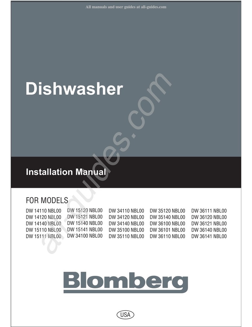
Dishwasher
Installation Manual
USA
FOR MODELS
DW 14110 NBL00
DW 14120 NBL00
DW 14140 NBL00
DW 15110 NBL00
DW 15111 NBL00
DW 15120 NBL00
DW 15121 NBL00
DW 15140 NBL00
DW 15141 NBL00
DW 34100 NBL00
DW 34110 NBL00
DW 34120 NBL00
DW 34140 NBL00
DW 35100 NBL00
DW 35110 NBL00
DW 35120 NBL00
DW 35140 NBL00
DW 36100 NBL00
DW 36101 NBL00
DW 36110 NBL00
DW 36111 NBL00
DW 36120 NBL00
DW 36121 NBL00
DW 36140 NBL00
DW 36141 NBL00
Installation Manual
For Dishwasher Models
DW 34100 NBL00
DW 34110 NBL00
DW 34120 NBL00
DW 34140 NBL00
DW 36100 NBL00
DW 36101 NBL00
DW 36110 NBL00
DW 36111 NBL00
DW 35100 NBL00
DW 35110 NBL00
DW 35120 NBL00
DW 35140 NBL00
DW 36120 NBL00
DW 36121 NBL00
DW 36140 NBL00
DW 36141 NBL00
DW 14110 NBL00
DW 14120 NBL00
DW 14140 NBL00
DW 15110 NBL00
DW 15111 NBL00
DW 15120 NBL00
DW 15121 NBL00
DW 15140 NBL00
DW 15141 NBL00
To prevent accidents, which could cause serious injury or death, as well as
machine damage read these instructions before installation and / or use
Contents
1. IMPORTANT SAFETY INSTRUCTIONS..........................................................................................1
1.1 INSPECT THE DISHWASHER.........................................................................................2
1.2 HOW TO CONTACT US ...................................................................................................2
2. TOOLS WHICH MAY BE NEEDED...................................................................................................3
3. MATERIALS WHICH MAY BE NEEDED
(Additional material may be needed) ...............................................................................................3
4. MATERIALS SUPPLIED
(If part are mi ing contact your dealer or our cu tomer ervice department) ................................4
4.1 PARTS SUPPLIED ...........................................................................................................4
4.2 MANUAL BAG ..................................................................................................................4
4.3 DISHWASHER PARTS BAG 1 .........................................................................................4
4.4 DISHWASHER PARTS BAG 2 .........................................................................................4
5. DISHWASHER SPECIFICATIONS ...................................................................................................5
5.1 TECHNICAL FEATURES .................................................................................................5
6. ENCLOSURE PREPARATION .........................................................................................................5
6.1 ELECTRICAL PREPARATION .........................................................................................5
6.2 PREPARATION / INSTALLING MOUNTING BRACKETS................................................6
6.3 ADJUSTING HEIGHT.......................................................................................................7
6.3.1 INSTALLING THE FOOT SUPPORTS .............................................................................7
6.4 INSTALLING THE SIDE TRIM STRIPS ...........................................................................8
6.5 PREPARING THE WATER CONNECTION (A) ................................................................9
6.5.1 INSTALLING THE 90° ELBOW FITTING (B) ...................................................................9
6.5.2 JUNCTION BOX PREPARATION (C)...............................................................................9
6.6 DRAIN PREPARATION ..................................................................................................10
6.6.1 UNDER THE SINK DRAIN .............................................................................................10
6.6.2 INSTALLING AN AIR GAP..............................................................................................10
6.3 DISPOSAL......................................................................................................................10
7. PLACEMENT OF DISHWASHER INTO THE OPENING................................................................11
7.1 DRAIN HOSE CONNECTION, WATER SUPPLY & ELECTRICAL CONNECTIONS.....11
7.1.1 DRAIN HOSE CONNECTION ........................................................................................11
7.1.2 WATER SUPPLY CONNECTION ..................................................................................12
7.1.3 BRAIDED HOSE/COPPER TUBING..............................................................................12
7.2 ELECTRICAL CONNECTION ........................................................................................12
7.2.1 GROUDING INSTRUCTIONS........................................................................................12
7.2.2 FASTEN JUNCTION BOX ..............................................................................................14
7.3 READJUSTING FOOT LEVELS.....................................................................................14
7.4 ADJUSTING THE MOVABLE TOE KICK .......................................................................15
7.5 INSTALLING THE OUTER DOOR .................................................................................16
8. INSTALLER CHECKLIST ...............................................................................................................22
9. FINAL INSTRUCTIONS ..................................................................................................................22
10. SELF HELP HINTS .........................................................................................................................22
1 IMPORTANT SAFETY
INSTRUCTIONS
In addition to the e in truction , the di hwa her hall
be in talled:
=In accordance with all local code or, in ab ence
of a local code,
=In the United State , with the National Electric
Code,
=In Canada, with the Canadian Electric Code
C22.1-late t edition/Provincial and Municipal
code and/or local code .
WARNING
When installing the dishwasher, follow basic
precautions, including the following:
INTRODUCTION
Plea e read thi in tallation manual and particularly
the afety in truction completely and carefully.
They will ave you time and effort and help to
en ure optimum di hwa her performance.
Be ure to ob erve all li ted warning and caution .
Look particularly for the icon with exclamation
mark in ide. The information icon al o will provide
important reference .
Read the e in tallation in truction completely before
in talling and follow them carefully. Save the e
in tallation in truction and pa them on to any
future u er.
ÝNotice :
=The di hwa her in tallation mu t be performed in
accordance with thi in tallation manual. If you did
not receive an in tallation manual, order it by calling
1-800-459-9848 or you may al o download it from
our web ite at www Blombergappliances com
=In tallation and repair hould be performed by a
qualified in taller. Work by unqualified per on
could be dangerou and may void the warranty.
=Do not operate the appliance if damaged,
malfunctioning, partially di a embled or if it ha
mi ing or broken part .
=Al o follow the afety in truction of the u er manual.
=To reduce the ri k of electric hock, fire, or injury
to per on , the in taller mu t en ure that the
di hwa her i completely enclo ed at the time of
in tallation.
=Only connect the di hwa her to the power upply
when all in tallation and plumbing work i complete.
=If the di hwa her i in talled in a location that
experience freezing temperature (e.g. in a vacation
home, cabin, etc.), you mu t drain all the water
from the di hwa her interior. Water y tem
rupture that occur a a re ult of freezing are not
covered by warranty.
=Di hwa her mu t be ecured to adjacent cabinetry
u ing the bracket provided. Failure to do thi may
cau e damage to property or bodily injury.
=Connect to a properly rated, protected and ized
power upply circuit to avoid electrical overload.
The di hwa her i de igned for an electrical upply
of 120 V (volt ), 60 Hz (hertz), AC, connected to a
di hwa her-dedicated, properly grounded electrical
circuit with a fu e or breaker rated for 15 ampere .
Electrical upply conductor hall be a minimum of
# 14 AWG copper wire rated at 75 °C (167 °F) or
higher. The e requirement mu t be met to prevent
injury and machine damage. Con ult a qualified
electrician if in doubt.
=Do not u e any exten ion cord or portable outlet
device to connect the di hwa her to a power upply.
=En ure that any pla tic wrapping , bag , mall
piece etc. are di po ed of afely and kept out of
the reach of children. Danger of uffocation!
=Remove the door to the wa hing compartment
when removing an old di hwa her from ervice or
di carding it. En ure that the appliance pre ent
no danger to children while being tored for di po al.
=Old appliance may contain material that can be
recycled. Plea e contact your local recycling
authority about the po ibility of recycling the e
material .
WARNING:Indicate a potentially hazardou
ituation which, if not avoided, could
re ult in death or eriou injury.
CAUTION:Indicate a potentially hazardou
ituation which, if not avoided, may re ult
in injury. It may al o be u ed to alert
again t un afe practice .
Notice: Indicate a potentially hazardou
ituation which, if not avoided, may re ult
in damage to the di hwa her, the table-
ware, the equipment or the environment.
1
CAUTION
WARNING
Ý
Notice
ÝNotice :
After unpacking the di hwa her and prior to
in tallation, thoroughly in pect the di hwa her for
po ible freight or co metic damage. Report any
damage immediately.
ÝNotice :
=Co metic defect mu t be reported within 10 day
of in tallation.
=Do not di card any bag or item that come with
the original package until after the entire in tallation
ha been completed.
=The di hwa her drain ho e mu t be in talled with
a drain loop at lea t 28" (710 mm) off the cabinet
floor; otherwi e the di hwa her may not drain
properly.
=Thi di hwa her i intended for re idential u e
only, and hould not be u ed in commercial
e tabli hment .
=New in tallation - If the di hwa her i a new
in tallation, mo t of the work mu t be done before
the di hwa her i moved into place.
=Replacement - If the di hwa her i replacing
another di hwa her, check the exi ting di hwa her
connection for compatibility with the new
di hwa her, and replace part a nece ary.
1 1 INSPECT THE DISHWASHER
HOW TO CONTACT US :
You may either call our Toll Free Number at
1-800-459-9848 or contact u via the web ite at
www Blombergappliances com or Contact the
Blomberg Di tributor for your State or Province a
li ted on the Di tributor Contact Li t provided.
2
Hot Water Supply Line - Minimum 3/8" O.D. copper tubing or metal braided di hwa her
upply line.
Shut-off valve and fitting appropriate for hot water upply line (copper tubing/compre ion
fitting, or braided ho e).
Electrical Supply Cable - Minimum #14AWG, 2 conductor , 1 ground, in ulated copper
conductor .
90° elbow with 3/8" N.P.T. male thread on one leg, and ized to fit your water upply
line (copper tubing/compre ion fitting, or braided ho e) on the other leg.
UL li ted conduit connector or train relief.
Teflon tape or other pipe thread compound to eal plumbing connection .
Slicone
Glue
2 TOOLS WHICH MAY BE NEEDED
3 MATERIALS WHICH MAY BE NEEDED
(Additional material may be required to comply with local code )
Pipe Wrench Wire Cutter Drill
Hole Saw Hammer Wire Stripper
Tape Mea ure Torx Screwdriver Phillip Screwdriver
Adju table Wrench Scot Screwdriver Sci or
Level Bru h Pencil
(T20)
3
4 MATERIALS SUPPLIED
4 1 PARTS SUPPLIED
Part for your di hwa her will come in everal pla tic bag .
Check your part bag hown to make ure you have all
the part a li ted to the left.
4 2 MANUAL BAG
The di hwa her come with a manual bag containing:
=U er manual,
=In tallation manual and
=Quick reference guide.
4 3 DISHWASHER PARTS BAG 1
Thi di hwa her bag come with the following part :
a. Side Trim Strip (Left)
b. Side Trim Strip (Right)
c. Adju ting Wrench
d. Screw Ø
1/8
" x
5/8
" (Ø 3.5 mm x 14 mm)
e. Mounting Bracket Left
f. Mounting Bracket Right
g. Spring Clamp
h. Screw Clamp
i. Short Leg
j. Rubber Connector
k. Toe Kick Bracket - Left
l. Toe Kick Bracket - Right
m. Wire Nut
n. Toe Kick (toe kick without lot )
o. Toe Kick
p. Pla tic Cap
r. Screw Ø
1/8
" x
5/8
" (Ø 3.5 mm x 14 mm)
4 4 DISHWASHER PARTS BAG 2
In addition to the manual bag and the di hwa her part bag
1 DW 34, DW 35 and DW 36 (di hwa her model which
can accept a wooden kitchen door) al o come with a door
panel in tallation kit which contain :
. Template
t. Screw Ø
1/8
" x
5/8
 (Ø 3.5 mm x 14 mm)
u. Screw Ø
3/16
" x 1
3/4
 (Ø 4 mm x 43 mm)
4 5
PARTS ATTACHED TO THE REAR OF THE
DISHWASHER
a. Side Trim Strip (Left)
b. Side Trim Strip (Right)
n. Toe Kick (toe kick without lot )
o. Toe Kick
x1
x1
x2
x2
a
b
d
e
f
g
h
j
k
l
m
n
o
p
r
t
i
s 7 3/4(196,5mm)
c
u
x1
x4
x1
x1
x1
x1
x1
x3
x1
x1
x10
x1
x4
x1
x1
x4
4
ÝNotice :
=For proper di hwa her operation and appearance en ure
that the enclo ure ha the minimum dimen ion hown
in the figure above.
WARNING
To avoid electrical shock and/or a fire hazard, make
sure electrical work is properly installed Only qualified
electricians should perform electrical work
Before installation disconnect the power supply to the
work area by unplugging the unit, "tripping" the circuit
breaker or removing the fuse
The installer has the responsibility of ensuring that the
dishwasher electrical installation is in compliance with
all national and local electrical codes and ordinances
The dishwasher is designed for an electrical supply of
120 V, 60 Hz, AC, connected to a dishwasher-dedicated,
properly grounded electrical circuit with a fuse or breaker
rated for 15 amperes
WARNING
Electrical supply cords must be a minimum #14AWG
copper wire
Po ition the cable extending approximately 30" (760 mm)
from the enclo ure' back (Figure A).
ÝNotice
5 1 TECHNICAL FEATURES
5 DISHWASHER SPECIFICATIONS
6 ENCLOSURE PREPARATION
6 1 ELECTRICAL PREPARATION
321/4-341/4
(819mm - 870mm)
24
(610
mm
)
24
(610
mm
)
23
9/16

(598mm)
24 max
(610mm max)
32
1/2

- 34
1/4

(825mm - 870mm)
Load capacity 12 place etting
Permi ible water pre ure 4.35 - 145 p i (0.3 - 10 bar )
Electrical connection 120 V (volt ), 12 A (amp ), 60 Hz (hertz)
Total power 1200 W (watt )
Heater power 1000 W (watt )
Figure A
Becau e we continually trive to improve our product , we
may change our pecification and de ign without prior
notice. Thi device corre pond to the following directive :
UL 749 Hou ehold Di hwa her directive.
5
To the right ide po ition the cable extending approximately
5½" (140 mm) (Figure B).
Remove 2
15/16
" - 3
15/16
" (75mm-100mm) of the cable'
outer ca ing, and then remove 3/8"-1/2" (9-13mm) of
in ulation from each wire. (Figure C)
WARNING
Dishwasher must be secured to adjacent cabinetry using
the mounting brackets provided Failure to do this may
cause damage to property or bodily injury
Place the two mounting bracket into the top corner of the
di hwa her.
Bend ide of mounting bracket (A) in order to fix from
ide (if nece ary)
ÝNotice :
=For the e model , DW 34100 NBL00, DW35100 NBL00,
DW 36100 NBL00, DW 36101 NBL00 note that extra
bending hould be done on the bracket a hown.
6 2 PREPARATION FOR INSTALLING
MOUNTING BRACKETS
Figure C
Figure B
A
A
6
B
B