manuals.online logo
Brands
  1. Home
  2. •
  3. Brands
  4. •
  5. Blonder tongue
  6. •
  7. Amplifier
  8. •
  9. Blonder tongue Galaxy III series User manual

Blonder tongue Galaxy III series User manual

A complete line of superior performance rated, mast mounted preamplifiers for any
home installation requirement.
• AllnewTransformerandPowerAddersimplifyhook-upandmounting.
• Lownoisefigureandmastmountdesignreduces“snow”onweakTVchannels.
• Excellentgainforimprovedreception.
• Increasedinputcapabilityminimizeseffectsofstronginterferingsignals.
• Unitsemploythemostmoderntechnologyforprotectionfromlightningand
powerlinesurges.
• Includesheavydutymastmountinghardwaretoinsuresecureinstallation.
INSTRUCTION MANUAL 651128300M
OneJakeBrownRoad,P.O.Box1000
OldBridge,NJ08857-1000USA
(800)523-6049•(732)679-4000•FAX:(732)679-4353
www.blondertongue.com
Amplifier Power Adder
Output Output
Stock No. Name (ohms) (ohms)
 5118 AbleU2III 300 300
 5119 AbleU2III75 75 75
 5219 AbleU2III75-75 75 75
 5122 VoyagerIII 300 300
 5123 SuburbanIII 75 75
 5124 VaulterIII 75 75
 5125 VaulterIIIDual 75 75(2)
Galaxy III Series
Preamplifiers
UHF/VHF UHF
OneJakeBrownRoad
OldBridge,NJ08857-1000USA
(800)523-6049•(732)679-4000•FAX:(732)679-4353
www.blondertongue.com
☛ Note: FM response is reduced to maintain distortion free
TV reception in the presence of strong FM signals. Preamp
will pass FM adequately in stronger signal areas, but is not
intended for critical weak signal FM preamplification.
INSTALLATION INSTRUCTIONS
PREAMPLIFIER CONNECTIONS
(Refer to Installation Diagrams I thru IV)
1a. Single antenna UHF or VHF only or UHF/VHF combined.
 1. Connecta300ohmtwinleadfromantennatoterminalsmarkedANTonpreamplifier.
 or2. Connecta75ohmcoaxialcablefromantennatoterminalmarkedANTon
preamplifier
or 1b.Separate UHF and VHF antennas.
Connecta300ohmtwinleadfromUHFantennatopreamplifierterminalsmarked
UHFANT.Connecta300ohmtwinleadfromVHFantennatopreamplifierterminals
markedVHFANT.
Be sure to leave enough slack in the twinlead to form a drip loop so rain
water does not enter the preamplifier case.
 2a. Using300ohmtwinlead,connectdownleadtoterminalsonpreamplifiermarkedTO
POWERSUPPLY.
 or2b. Using75ohmcoaxialcable,connectdownleadtoterminalonpreamplifiermarkedTO
POWERSUPPLY.
  Keepdownleadasfarawayaspossiblefromtheinputwire,aminimumoftwoinches.
Donotplaceanydeviceinthedownleadbetweenthepreamplifierandpowersupply.
Asignalsplitter,forexample,maynotpasspowerandwouldpreventthepreamplifier
fromoperating.
 3. Mountpreamplifiertotheantennamastasshown.Ifmastisattachedtoachimney,
mountthepreamplifierbelowthechimneytoptoavoidexposuretofumes.
BE SURE THE ANTENNA MAST IS WELL GROUNDED.
 4. Runthedownleadasshown,usingstand-offs.Formadriploopwheredownlead
WARNING: TO PREVENT SHOCK HAZARD, DO NOT EXPOSE THIS
UNIT TO RAIN OR MOISTURE
NOTE TO CATV INSTALLERS
This reminder is provided to call the CATV System Installer’s atten-
tion to Article 820-40 of the NEC that provides guidelines for proper
grounding and, in particular, specifies that the cable ground shall be
connected to the grounding system of the building, as close to the point
of cable entry as practical.
!
CAUTION
RISK OF ELECTRIC SHOCK
DO NOT OPEN
The lightning flash with
arrowhead symbol within an
equilateral triangle is intended
to alert you to the presence of
uninsulated “dangerous volt-
age” within the product’s enclo-
sure that may be of sufficient
magnitude to constitute a risk of
electricalshocktopersons.
The exclamation point within an
equilateral triangle is intended
to alert you to the presence of
important operating and mainte-
nance (servicing) instructions in
the literature accompanying the
product.
TO REDUCE THE RISK OF ELECTRICAL SHOCK, DO NOT REMOVE
COVER
FROM THIS UNIT. NO USER-SERVICEABLE PARTS INSIDE.
2
3 6
Combined UHF/VHF
UHF only or VHF only
III
1a 1
22b
4
III
For Stock Nos.
5116, 5119,
5123, 5219
Separate UHF
and VHF
IV
1b
2b
4
IV
For Stock Nos.
5124, 5125
Separate UHF
and VHF
II
1b
4
II
For Stock Nos.
5121, 5122
2a
Combined UHF/VHF
UHF only or VHF only
I
1a
4
I
For Stock Nos.
5113, 5118, 5120
Installation Diagrams Preamplifier
3
2a
STOCK NO.
5121
MADE IN USA
FROM AMP
SET1
SET2
SPLITTER-POWER ADDER
300 OHM
Galaxy
VI
Splitter/
Power Adder
VI
For Stock No. 5121
STOCK NO.
MADE IN USA
FRO AMP
TO TV SET
SPLITTER-POWER ADDER
300 OHM
Galaxy
V Power Adder
VI
For Stock No.
5113, 5118, 5120, 5122
MADE IN USA
FROM AMP
SPLITTER
POWER
ADDER
75 OHM
Galaxy
VIII
Splitter/
Power
Adder 21
MADE IN USA
SPLITTER
POWER
ADDER
75 OHM
Galaxy
TV SETFROM AMP
VII Power Adder
VII
For Stock No.
5116. 5119, 5123, 5124, 5219
VIII
For Stock No. 5125
POWER
SUPPL
LABORATORIES, IN
C
.
Itallatio Diara Splitter-Power Adder
Power Spply
Forfuturereference,recordthemodelnameandstocknumberofyour
mast-mountpreamplifierunitbelow.
Pleaseusethisinformationifcontactingyourdistributororourfactory
regardinganyserviceproblem.
Model Name: ________________________________
Stock No: ___________________________________
APPLICATIONS
Anyquestionsregardingunusualsignalconditionsandapplicationsshouldbedirectedto:
SYSTEMSENGINEERINGDEPT.BLONDERTONGUELABORATORIES,INC.
SERVICE
Thisproductisdesignedtogivelongtrouble-freeservicewheninstalled
accordingtotheinstructionsinthisbooklet.Ifyoususpectamalfunction
asevidencedbyexcessive“snow”ontheTVpicture,checkallconnections
betweenantenna,amplifier,andTVset.Besurethat
connectionsontheamplifierarenotreversed.Alsocheckcablesfor
breakageorshorts.Ifthisdoesnotrestorenormaloperationreturntheunit
to your dealer, or refer to Returning Product for Repair (or Credit)
below.
Returning Product for Repair (or Credit)
A Return Material Authorization (RMA) Number is required on
all products returned to Blonder Tongue,regardlessiftheproductis
beingreturnedfor
repairorcredit.Beforereturningproduct,pleasecontacttheBlonder
TongueServiceDepartmentat1-800-523-6049,Ext.4256orvisitour
☛ Note: The same power adder (with a common stock number) is used
for several different mast-mounted preamplifiers. Referring to the
Power Adder stock number only will not enable us to determine the
unit which you have purchased.
DO NOT OVERTIGHTEN STRIPLESS
SCREWS.
TIGHTEN ONLY ENOUGH TO PIERCE 300-
OHM TWINLEAD
STRIPLESS SCREWS ARE FULLY
TIGHTENED WHEN THE TEETH
OF THE WASHERS ARE BURIED
COAXIAL CABLE CONNECTIONS:
(Figure 1)
A. CutAndremove5/8''ofjacket
NON-BONDED FOIL OR NON-FOIL
CABLE
1. Bendfoiland/orbraidbackleaving
insulationexposed.
2. Carefullycutoffandremove1/2''
ofinsulation.(Donotnickcenter
conductor). Clean conductor if any
insulation adheres to it.
3. Slideferruleoverfoiland/orbraid.
Non-BondedFoil-Pushentire
connectormandrelUNDERfoil.Non-
Foil-Pushentireconnectormandrel
BETWEENbraidandinsulation.
BONDED FOIL
1. Bendbraidbackleavingfoilexposed.
2. Carefullycutoffandremove1/2''
offoilandinsulation.(Donotnick
center conductor). Clean conductor if
any insulation adheres to it.
3. Slideferruleoverbraid.Pushentire
connectormandrelOVERfoil.
4. Positionferruleovermandreland
crimp
gradually(donotexertsudden
pressure).
5. Cutoffcenterconductor1/8''to
3/16''in
frontofconnectorandtrimoffexcess
foiland/orbraid.
TWINLEAD CABLE CONNECTIONS.
1. Stripabout1/2inchofinsulation
fromthecableendandexposethe
twocopper
wiresinside.
2. Foldthetwowiresbackoverthe
cableend.
Besuretokeepthemseparated.
3. Loosenthecableclampingscrews
4 5
POWER ADDER and TV SET CONNECTIONS
(Refer to Installation Diagrams V thru VIII)
 1. ConnectthepreamplifierdownleadtothePOWERADDERatthe
terminalmarkedFROMAMP.
 2. RefertoStockNo.ofthepreamplifierbeinginstalledandmakethe
connectionsbetweenthePOWERADDERandTVset(s)asdetailed
below.
Stock No.
5113 Connecta300ohmtwinleadfromthetwoterminalsmarkedTOTV
SETtotheVHFterminalsontheTVset.
5116 Connecta75ohmcoaxialcableattheterminalmarkedTOTVSET.
Attacha300/75ohmMatchingTransformer(notsupplied)tothe
otherendofthecableandconnecttheTransformerleadstotheVHF
terminalsoftheTVset.
5118 Connecta300ohmtwinleadfromtheterminalmarkedTOTVSET
totheUHF
terminalsontheTVset.
5119 Connecta75ohmcoaxialcableattheterminalmarkedTOTVSET.
5219 Attacha300/75ohmMatchingTransformer(notsupplied)tothe
otherendofthecable.ConnecttheTransformerleadstotheUHF
terminalsoftheTVset.
5120 Connecta300ohmtwinleadtotheterminalsmarkedTOTVSET.
5121 Connecta300ohmtwinleadtothetwoterminalsmarkedSET
1.ConnectanothertwinleadtothetwoterminalsmarkedSET2.
AttachaU/VBandSeparator
(notsupplied)totheotherendofeachtwinlead.Connecttheleads
oftheBandSeparatorstotheirrespectiveUHFandVHFterminalson
theTVsets.
5122 AttachaU/VBandSeparator(notsupplied)totheotherendofthe
twinlead.ConnecttheleadsoftheBandSeparatortotheUHFand
VHFterminalsoftheTVset.
5123 Connecta75ohmcoaxialcableattheterminalmarkedTOTVSET.
5124 AttachaU/VBandSeparator(notsupplied)attheTVsetendof
cable.ConnecttheleadsoftheBandSeparatortotherespectiveUHF
andVHFterminalsontheTVset.
5125 Connectaseparate75ohmcoaxialcabletotheterminalsmarked
SET1andSET2.AttachaU/VBandSeparator(notsupplied)tothe
TVsetendofeachcable.ConnecttheBandSeparatorleadstotheir
respectiveUHFandVHFterminalsoneachTVset.
  3. MountPOWERADDERwithscrewssupplied,inaconvenient
location.
  4. PlugTRANSFORMERintoa117voltACoutlet.Thepreamplifier
isnowoperating.Itisnotnecessarytounplugtheunitwhenthe
TVsetisnotinusesincetheunitdrawsverylittlecurrent,less
CAUTION
Figure 1
Figure 2

Other Blonder tongue Amplifier manuals

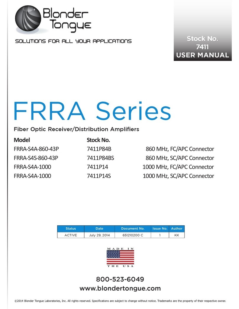
Blonder tongue FRRA Series User manual

Blonder tongue

Blonder tongue FRRA Series User manual

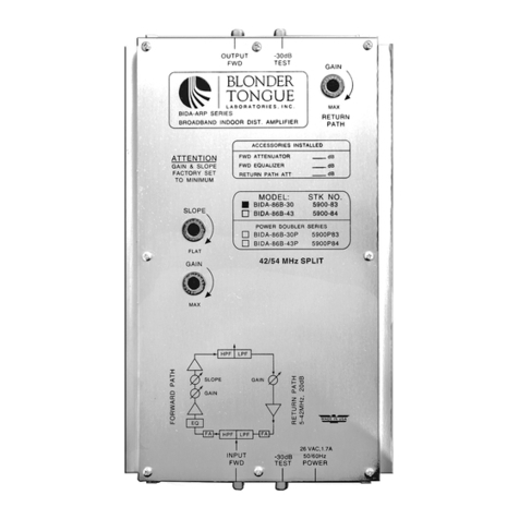
Blonder tongue BIDA 86B-30 User manual

Blonder tongue

Blonder tongue BIDA 86B-30 User manual

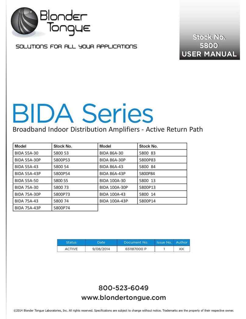
Blonder tongue BIDA Series User manual

Blonder tongue

Blonder tongue BIDA Series User manual

Blonder tongue FRRA-S4A-860-43P User manual

Blonder tongue

Blonder tongue FRRA-S4A-860-43P User manual

Blonder tongue HDA-4-860-24 User manual

Blonder tongue

Blonder tongue HDA-4-860-24 User manual

Blonder tongue MUVB-45 User manual

Blonder tongue

Blonder tongue MUVB-45 User manual

Blonder tongue BIDA 5900 Series User manual

Blonder tongue

Blonder tongue BIDA 5900 Series User manual

Blonder tongue FRDA Series User manual

Blonder tongue

Blonder tongue FRDA Series User manual

Blonder tongue ZCM-48-550 Series User manual

Blonder tongue

Blonder tongue ZCM-48-550 Series User manual

Blonder tongue CMA-b User manual

Blonder tongue

Blonder tongue CMA-b User manual

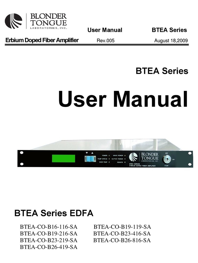
Blonder tongue BTEA-CO-B16-116-SA User manual

Blonder tongue

Blonder tongue BTEA-CO-B16-116-SA User manual

Blonder tongue EQAM-420A User manual

Blonder tongue

Blonder tongue EQAM-420A User manual

Blonder tongue FIBT Series User manual

Blonder tongue

Blonder tongue FIBT Series User manual

Blonder tongue DA-33 User manual

Blonder tongue

Blonder tongue DA-33 User manual

Blonder tongue BIDA 550-30 User manual

Blonder tongue

Blonder tongue BIDA 550-30 User manual

Blonder tongue BODA 86A-30P User manual

Blonder tongue

Blonder tongue BODA 86A-30P User manual

Blonder tongue hda series User manual

Blonder tongue

Blonder tongue hda series User manual

Blonder tongue 1465 User manual

Blonder tongue

Blonder tongue 1465 User manual

Popular Amplifier manuals by other brands

Kramer VM-4HD user manual

Kramer

Kramer VM-4HD user manual

Taga Harmony HTA-800B instruction manual

Taga Harmony

Taga Harmony HTA-800B instruction manual

Elgar SW 5550AE Operation manual

Elgar

Elgar SW 5550AE Operation manual

Tektronix 7A18A instruction manual

Tektronix

Tektronix 7A18A instruction manual

Pro-Ject Audio Systems AMP BOX DS User instructions

Pro-Ject Audio Systems

Pro-Ject Audio Systems AMP BOX DS User instructions

McIntosh MA352 owner's manual

McIntosh

McIntosh MA352 owner's manual

Accustic Arts MONO III MK2 manual

Accustic Arts

Accustic Arts MONO III MK2 manual

Giga-tronics GT-1000B Operation manual

Giga-tronics

Giga-tronics GT-1000B Operation manual

Auralic TAURUS user guide

Auralic

Auralic TAURUS user guide

Boss Audio Systems CE2800D user manual

Boss Audio Systems

Boss Audio Systems CE2800D user manual

Rotel RC-850 Technical manual

Rotel

Rotel RC-850 Technical manual

American Audio VLP User instructions

American Audio

American Audio VLP User instructions

AUSTRALIAN MONITOR SA120 operating manual

AUSTRALIAN MONITOR

AUSTRALIAN MONITOR SA120 operating manual

Pioneer SA-710 operating instructions

Pioneer

Pioneer SA-710 operating instructions

Technics SU-A800 Service manual

Technics

Technics SU-A800 Service manual

Glass Ware 24V Aikido user guide

Glass Ware

Glass Ware 24V Aikido user guide

Hagen Diezel user manual

Hagen

Hagen Diezel user manual

VINCENT SA-T7 MK Instructions for use

VINCENT

VINCENT SA-T7 MK Instructions for use

manuals.online logo
manuals.online logoBrands
  • About & Mission
  • Contact us
  • Privacy Policy
  • Terms and Conditions

Copyright 2025 Manuals.Online. All Rights Reserved.