manuals.online logo
Brands
  1. Home
  2. •
  3. Brands
  4. •
  5. Blonder tongue
  6. •
  7. Modulator
  8. •
  9. Blonder tongue MIDM-806C User manual

Blonder tongue MIDM-806C User manual

INSTRUCTION MANUAL
One Jake Brown Road
Old Bridge, NJ 08857-1000 USA
(800) 523- 049 • (732) 79-4000 • FAX: (732) 79-4353
www.blondertongue.com
©2004 Blonder Tongue Laboratories, Inc. All rights reserved. Specifications are subject to change without notice. Trademarks are the property of their respective owner.
MIDM-806C
Demodulator
Stock No. 7740C
51191400C
De cription
The MIDM-80 C is a professional quality single channel, agile audio/video demodulator. It provides an A/V output from
any VHF, UHF or CATV channel (54-80 MHz) and is designed for use in the Blonder Tongue Modular Headend System.
The MIDM-80 C demodulator and the MICM/AMCM modulator can be paired to perform off-air channel processing or to
cherry pick cable channels.
RF
Input Frequency Range:
54 - 80 MHz (Broadcast Ch’s. 2- 9, Cable
Ch’s 2-125) VHF, UHF, CATV (STD, IRC, HRC)
Input Level Range:
Antenna Mode: -5 to +30 dBmV
CATV Mode: +2 to +12 dBmV with 70 Channel Input
Input Impedance: 75 Ohm
Video
Video Output Level: 1 Vpp Adj.
Video Output Impedance: 75 Ohm
Video S/N Ratio 4 MHz BW:
>=44 dB (CATV Mode, 70 Ch. Input 2-12 dBmV, Measured
Channel -3 dB)
Video Response 0.2 to 4 MHz: ± 2 dB Relative to 0.2 MHz
Differential Gain: 5% Typical
Differential Phase: 5 Deg. Typical
Chrominance to Luminance Delay: -40 ns Typical
Chrominance to Luminance Gain: 90% Typical
K Factor: <= 5%
Short Time Distortion: <= 5%
Audio
Audio Output Level: 1 Vpp Adj.
Audio Impedance: 00 Ohm Unbalanced
Electrical
Power Requirements
12 VDC: 140 mA
5 VDC: 150 mA
2.5 Watts
Mechanical
Dimensions: 1.15 x 3.5 x 7.5 in.
Weight: 13.5 oz.
Temperature Range: 0° to 50° C
Connector (Rear)
RF Input: “F” Type Female
Video Output: “F” Type Female
Audio Output: RCA Phono Female
Power: Locking Header 3 Pin
Control (Front)
Channel Selection: UP/DOWN Push Button
Power Lock: Push Button
C/ANT Mode: Push Button
Video Level: Control
Audio Level: Control
Indicator
Channel/Mode: 2 Digit, 7 Segment RED LED Display
+ 100 Channel: RED LED
Specification
One Jake Brown Road
Old Bridge, NJ 08857-1000 USA
(800) 523- 049 • (732) 79-4000 • FAX: (732) 79-4353
www.blondertongue.com
Operating Control & Indicator
Front Panel
All operating controls are located on, or are accessible from the front panel.
MIDM-806C
Stock No. 7740C
BLONDER
TONGUE
VA
PWR C/ANT
CH CH
LOCK +100
6
9
7
8
54
12
3
Indicator lights
when in Standby
Channel
Display
Lock
Indicato
r
1. Video - Adjusts video output level
2. Audio - Adjusts audio output level
3. Channel LED - Displays ANT or CATV
channel
4. C/ANT Mode Button - Press button to enter
the mode selection menu. Use the channel
UP/DOWN buttons to select the type of
channel system required as follows:
Press C/ANT button again when selection
is completed.
5. Power - ON/OFF push button
. Channel DOWN - Increments channel by -1
7. Channel UP - Increments channel by +1
8. +100 LED - When depressed, RED LED lights to
indicate channels 100 and higher.
9. Lock - Depressing lock button locks present channel or
mode in memory preventing inadvertent change. A user
must depress the lock channel button again for any
channel/mode changes.
Rear Panel
All the connectors are located the rear panel.
1
3
4
2
1. Video Output - Standard negative sync video at a 0.5 to 1.5 Vp-p level.
2. Audio Output - Adjustable 0.5 to 1.5 Vp-p
3. Power - The polarized power connector accepts +12 VDC, +5 VDC and ground
4. ANT/CATV - RF input from antenna or CATV drop
Operating Procedure
Connect the power input connector to the power supply. A LED bar lights to indicate the unit is in standby.
Connect the video/audio connectors and the RF input to the system.
Press PWR. The LED display will show the number of the latest channel selected.
Press C/ANT to enter the mode selection menu. Use the channel UP/DOWN button to select the type of channel system
required. Press C/ANT again when selection is completed.
Use CH CH to select the channel required.
A channel number higher than CH 99 is represented by the +100 indicator and the number shown on the LED display.
The +100 indicator represents the one hundred digit of the channel number.
Example: CH120 is displayed as 20 and the +100 indicator.
Adjust for proper video output level by tuning the video potentiometer.
Adjust for proper audio output level by tuning the audio potentiometer.
Press LOCK to lock-in the panel controls to prevent inadvertent channel or mode changes.
The LOCK indicator is lit when unit is in the LOCK mode.
Display Channel System
5 STD (CATV)
H HRC (CATV)
I IRC (CATV)
U Broadcast (ATV)
▲▼

Other Blonder tongue Modulator manuals

Blonder tongue BAVM-860SAW User manual

Blonder tongue

Blonder tongue BAVM-860SAW User manual

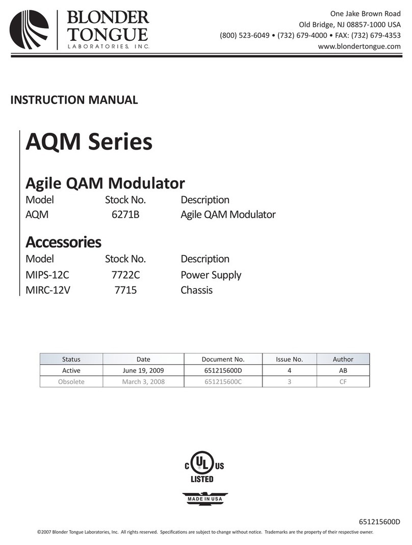
Blonder tongue AQM Series User manual

Blonder tongue

Blonder tongue AQM Series User manual

Blonder tongue MDDM-860 User manual

Blonder tongue

Blonder tongue MDDM-860 User manual

Blonder tongue BAVM-860 SAW Series User manual

Blonder tongue

Blonder tongue BAVM-860 SAW Series User manual

Blonder tongue AM-60-550 User manual

Blonder tongue

Blonder tongue AM-60-550 User manual

Blonder tongue FA1M-50-860 User manual

Blonder tongue

Blonder tongue FA1M-50-860 User manual

Blonder tongue ZFMSM User manual

Blonder tongue

Blonder tongue ZFMSM User manual

Blonder tongue HDE-2S-IP User manual

Blonder tongue

Blonder tongue HDE-2S-IP User manual

Popular Modulator manuals by other brands

Lemco HDMOD 5S quick start guide

Lemco

Lemco HDMOD 5S quick start guide

Satlink WS-8901U user manual

Satlink

Satlink WS-8901U user manual

Alcad MS-551 Tech note

Alcad

Alcad MS-551 Tech note

Pico Macom MPCM45 Installation and operation manual

Pico Macom

Pico Macom MPCM45 Installation and operation manual

Paia 4710 manual

Paia

Paia 4710 manual

Jensen KVFM1 How to install and operate

Jensen

Jensen KVFM1 How to install and operate

Softel SFT3542HA user manual

Softel

Softel SFT3542HA user manual

IKUSI MHD-201 Programming guide

IKUSI

IKUSI MHD-201 Programming guide

Holland SAWM60 manual

Holland

Holland SAWM60 manual

Mutable Instruments Tides quick start guide

Mutable Instruments

Mutable Instruments Tides quick start guide

ZyCast digi-MOD RL-DM4000D Quick install manual

ZyCast

ZyCast digi-MOD RL-DM4000D Quick install manual

Televes TOX Series quick guide

Televes

Televes TOX Series quick guide

Comark EXACT-V2 user manual

Comark

Comark EXACT-V2 user manual

Triplett 3296 instruction manual

Triplett

Triplett 3296 instruction manual

Dexing Fiber Labs NDS3332 user manual

Dexing

Dexing Fiber Labs NDS3332 user manual

Pico Macom MPCMA Installation and operation manual

Pico Macom

Pico Macom MPCMA Installation and operation manual

FTE Maximal MODIG S user manual

FTE Maximal

FTE Maximal MODIG S user manual

Eela Audio EA 946 Instructions for use

Eela Audio

Eela Audio EA 946 Instructions for use

manuals.online logo
manuals.online logoBrands
  • About & Mission
  • Contact us
  • Privacy Policy
  • Terms and Conditions

Copyright 2025 Manuals.Online. All Rights Reserved.