BLU Products NEO JR User manual

Customer Service Service Manual
1/ 41
BLU NEO JR
SERVICE MANUAL

Customer Service Service Manual
2/ 41
CAUTIONS
Please refer to the phone’s user’s guide for instructions relating to operation, care, and maintenance, which include
important safety information.
Servicing and alignment must be undertaken by qualified personnel only.
Ensure all work is carried out at an anti-static workstation and that an anti-static wrist strap is worn.
Use only approved components as specified in the parts list.
Ensure all components, modules, screws, and insulators are correctly re-fitted after servicing and alignment
Ensure all cables and wires are repositioned correctly
Electrostatic discharge can easily damage the sensitive components of electronic products. Therefore, every service
supplier must observe the precautions which mentioned above.
Content
1. Brief Introduction….…………………………………………………………….…………………….….3
2. Tools………………………………………………………………………………………………………..4
3.Assemble & Dissemble
Dissembly..................…………………………………………………………...………………...5~6
Assembly…………………………………………………………………………………………...7~8
4. Picture of main board
A&B side of PCBA ...…………….…………………………………………….………….…………..9
A&B of PCBA Layout………….….………….……………………………..………………….…....10
5. System Block Chart………………………………………………………..…………………………...11
6. Unit Circuit Map...…............................................................................................................12~22
7. Trouble Shooting Guide …..……………………………………….…………………………….23~34
8. Upgrading ………………..……………………………………….……………………………….35~43
9. CIT testing……………………………………………………………………………………………….44

Customer Service Service Manual
3/ 41
CHAPTER 1 INTRODUCTION
SPEC:
GSM Band:850/900/18001900MHz
Size:117X62.5X11mm
Camera: 0.3 Mega-H /1.3 Mega-S, 0.3 Mega
Image: 1280*960
Lithium Battery:1300mAh
Bluetooth Version:BT 4.0
Main Function
Dual Card Dual Standby Full Touch Smartphone
Android 4.2
CPU MT 6572A/E (1GHZ, dual-core)
3.5" HVGA320*480 P+F
Camera:0.3 Mega-H /1.3 Mega-S, 0.3 Mega
512MB+256MB
Dual SIM
Data Segment: EDGE DL, GPRS

Customer Service Service Manual
4/ 41
CHAPTER 2 SERVICE TOOLS
Voltage regulator
Multimeter
Iron
Hot air gun
Solder wire, soldering paste
Computer and software download cable
Metal tweezers, Screw driver etc
Pick
Driver
Tweezers
Wrist
groun
ding
Antistatic
SW
upDownlo

Customer Service Service Manual
5/ 41
CHAPTER 3 DISASSEMBLY AND ASSEMBLY
3.1 DISASSEMBLY
Remove the Battery cover…….……..………………... 1
Remove the PET flakes…………….…………..…2
Remove the back cover ………………………………4
Remove the TP FPC………………..………...………..5
unscrew the 7 screws……….……………..………..3
Remove the LCD BY electric iron
………...…………….……... 6


Customer Service Service Manual
7/ 41
3.2 ASSEMBLY
Install the PCBA……………..……..………….………..4
Install the TP…………………..………………....……3
Install the LCD BY electric iron..………………....…..…1
Tear off protection film………………………………….2
Install the TP connector…………..……….………...5
Install the back cover……..…………………………...... 6


Customer Service Service Manual
9/ 41
CHAPTER 4 SYSTEM BLOCK DIAGRAM
4.1、PCBA A-Side
PCBA-B-Side
J403
Battery connector
U100
RF PA
U800
GPS/BT/WIFI/FM
4in1chip
U201
CPU
U202
FLASH(4G)
J500
Earphone connector
U203
FLASH(2G)
U400
Power
Management
Ic
J510
LCD connector
J3
Camera connector
U107
RF IC
J703 IO

Customer Service Service Manual
10 / 41
4.2:Side A layout
Side B layout

Customer Service Service Manual
11 / 41
CHAPTER 5 CIRCUIT INSTRUCTION

Customer Service Service Manual
12 / 41
CHAPTER 6 UNIT CIRCUIT PRINCIPLE INTRODUCTION
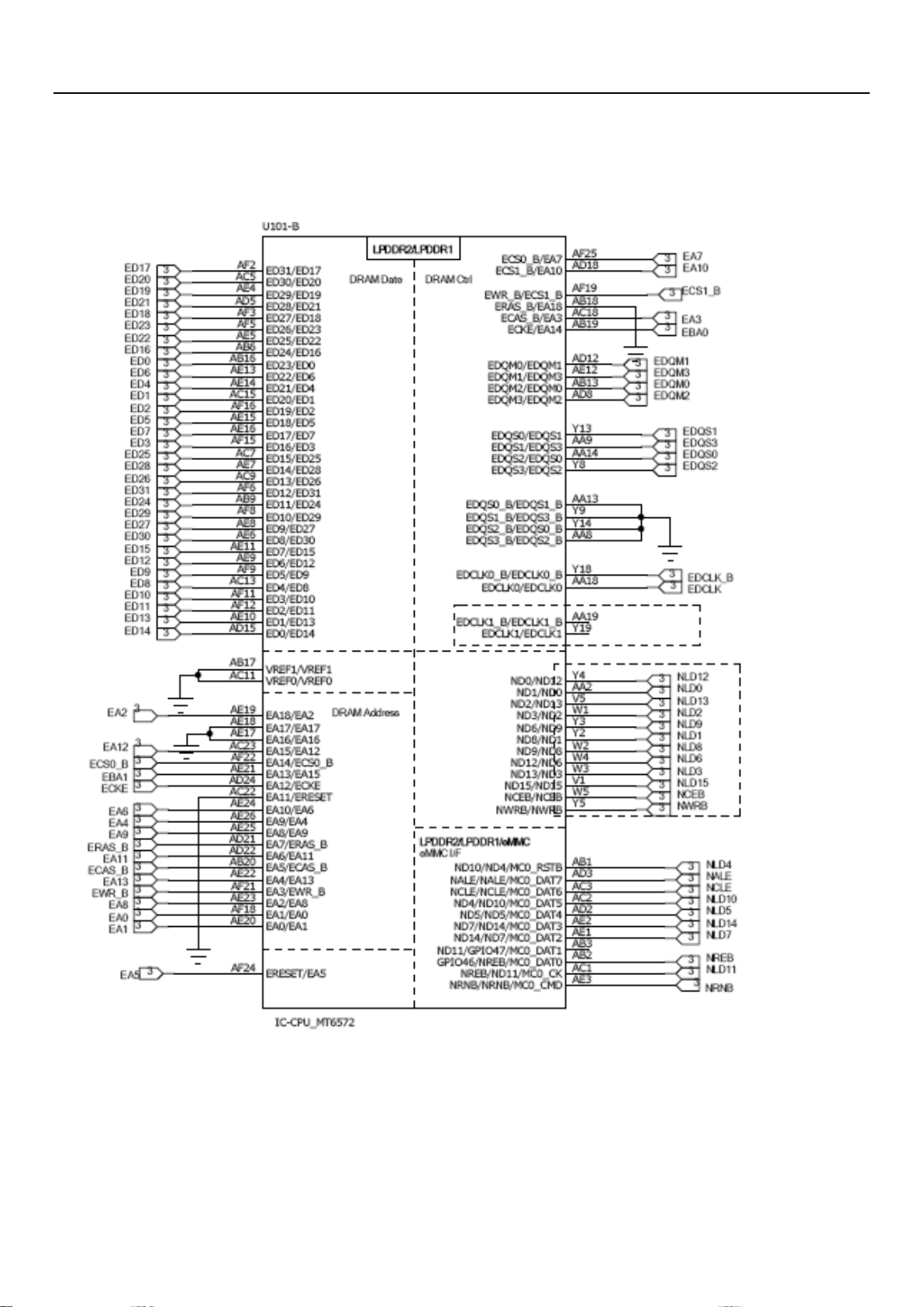
6.1 MT6572 INTRODUCTION
Baseband CPU circuit introduction for power supply
System Overview
MT6572 is a highly integrated baseband platform incorporating both modem and application
processing subsystems to enable 3G smart phone applications, with integrated Bluetooth, WILAN
and GPS modules. The chip integrates a Dual-core ARM○
R cortex-A7 MP coreTM operating up to
1.2Ghz,an ARM Cortx-R4 MCU and a powerful multi-Standard Video accelerator. MT6572 supports
various interfaces, including parallel/serial NAND flash memory and 32-bit LPDDR2

Customer Service Service Manual
13 / 41
6.1.1: Introduction for baseband chip CPU part circuit
Base station
interface
RF TX
Control
Camera
Control
Customer Service Service Manual
14 / 41

Customer Service Service Manual
15 / 41
6.2 Power management IC MT6323
General Descriptions
MT6323 is a power management system chip optimized for 2G/3G handsets and
smart phones, especially based on the MdeiaTek Mt6572 system solution. MT6323
contains 3 buck converters and 24 LDOs, which are optimized for specific 2G/3G/smart
phone subsystems. MT6323 provides mono 0.7W into 8Ω, high efficiency Class AB/D
audio amplifiers and flexibility for various applications of indicator LED drivers. It
supports up to 4 channel LEDs with independent controlled. Flexible control includes:
register mode, PEM mode and breath mode.

Customer Service Service Manual
16 / 41

Customer Service Service Manual
17 / 41
6.3 System Overview
The MT6166 is a RF transceiver targeted at high speed 2G/3G-FDD/TDD multi-mode
smart phone and tablet computers implanted in 40nm CMOS. The RF transceiver function is
fully integrated. This document briefly introduces the RF macros in MT6166.

Customer Service Service Manual
18 / 41
6.4: RF -MT6166
6.5 I/O connector (5PIN)

Customer Service Service Manual
19 / 41
6.6 Four in one chip MT6627
MT6627 is a 4-in-1 connectivity chip which contains a WIFI/Bluetooth Transceiver, a GPS receiver, and a FM
receiver front-ends, along with integrated passive device(IPD) in a QFN40 package. Simplified block diagram and
how MT6627 connects to a companion modem is shown in Figure 1. In Figure 1, RF input/output are, respectively.
An always on low-dropout regulator (ALDO) provides supply voltage to top control logics in MT6627.The top
control logics can control each subsystem independently. Each subsystem also has dedicated LDOs, too. A thermal
sensor and its ADC (analog=to-digital converter) is provided to monitor MT6627 temperature variation. MT6627
does not have its dedicated crystal oscillator. It either uses an extremely (maybe temperature compensated)
oscillator, or uses the clock source from companion chips in the platform such as MT6166.
For WIFI and Bluetooth, MT6627 provides an advanced switching mechanism which allows fast switching
between WIFI and BT modes. Hardware sharing and reuse is maximized. The transceiver front-ends are on
MT6627 while the ADC/DAC (analog-to-digital converter/digital-to-analog converter) are in the companion
modem chip. The interface driver/receiver buffer are designed to drive PCB trace loading. The GPS/Glonass IP in
MT6627 supports both standards, depending on if the companion modem supports Glonass or not. Its partition is
similar to WIFI/Bluetooth such that the ADC/DAC is in the companion modem chip. In contrast, the FM system
intearates the modem and ADC in MT6627. And no interface drivers/buffers are required.

Customer Service Service Manual
20 / 41
6.7: Four in one MT6627
Other BLU Products Cell Phone manuals

BLU Products
BLU Products VIEW 1 User manual

BLU Products
BLU Products J10L User manual

BLU Products
BLU Products JOY FLEX User manual

BLU Products
BLU Products G63 User manual

BLU Products
BLU Products Jenny User manual

BLU Products
BLU Products G33 User manual

BLU Products
BLU Products BLU DASH User manual

BLU Products
BLU Products G93 User manual

BLU Products
BLU Products Life Pure User manual

BLU Products
BLU Products BLU VIVO IV User manual


