Bludee AC800 User manual

AC800 V2.00
AC800
USER MANUAL
Service and support: 443-380-0088
www.bludee.com

AC800 V2.00
Description: Recover, recycle, and recharge machine for use with 134a equipped air conditioning systems.
Product Information
Record the serial number and year of manufacture of this unit for future reference. Refer to the product
identification label on the unit for information.
Serial Number: ____________________ Year of manufacture: ________________
DISCLAIMER: Information, illustrations, and specifications contained in this manual are based on the latest information available
at the time of publication. The right is reserved to make changes at any time without obligation to notify any person or organization
of such revisions or changes. Further, Bludee shall not be liable for errors contained herein or for incidental or consequential
damages (including lost profits) in connection with the furnishing, performance, or use of this material. If necessary, obtain
additional health and safety information from the appropriate government agencies, and the vehicle, refrigerant, and lubricant
manufacturers.

AC800 V2.00
1/16
INDEX
Specifications............................................................................................................................................................................. 2
General safety guide .................................................................................................................................................................. 3
Component identification .......................................................................................................................................................... 4
Function description .................................................................................................................................................................. 7
Preparations before operation.................................................................................................................................................... 8
1. Unlock tank load cell..................................................................................................................................................... 8
2. Tank fill.......................................................................................................................................................................... 8
3. Non-condensable purge ................................................................................................................................................. 8
Operating procedure .................................................................................................................................................................. 9
Recovery function.............................................................................................................................................................. 9
Evacuation function........................................................................................................................................................... 9
Oil injection function......................................................................................................................................................... 9
Refrigerant charging function.......................................................................................................................................... 10
Tank fill............................................................................................................................................................................ 10
Flushing function (COR,Compressor Oil Recovery,Optional)..................................................................................... 11
Automatic function mode ................................................................................................................................................ 11
System Setting ......................................................................................................................................................................... 12
Calibration ....................................................................................................................................................................... 12
Database........................................................................................................................................................................... 12
Record ............................................................................................................................................................................ 12
Unit settings ................................................................................................................................................................... 12
Empty container weight set ............................................................................................................................................. 12
Component test .............................................................................................................................................................. 12
Caring for your equipment....................................................................................................................................................... 13
Update...................................................................................................................................................................................... 14
Maintenance reminding ........................................................................................................................................................... 15
Packing list ............................................................................................................................................................................ 166

AC800 V2.00
2/16
Specifications
➢Dimension:Package in crate 720*670*1190mm (29”x26”x47”); Unpacked machine 630*560*1075mm
(24”x22”x46”)
➢Input power:AC110V±10%~60Hz
➢Compressor power:3/8HP
➢Average gas state refrigerant recovery speed:0.55LBS/min.
➢Recovery rate: 95%.
➢Pressurization to speed up old oil discharge.
➢Vacuum pump capacity:60L(16GAL) /min.
➢Individualized filter-drier capacity: 600ml
➢Accuracy of gas cylinder load cell:±10g
➢Accuracy of oil bottle load cell:±3g
➢Gas cylinder capacity:10KG (22LBS)
➢New oil bottle capacity:250ml
➢Used oil bottle capacity: 400ml
➢Condenser and cooling fan included.
➢Max. Pressure:20bar
➢Charge speed:2Kg/Min(max.)
➢LCD display:4.3-inch, TFT full color
➢High pressure gauge range:-1bar~40bar
➢Low pressure gauge range:-1bar~22bar
➢A/C database included, update through USB port.
➢Automatic service reminding. The equipment provides 600 operations totally (each recovery or vacuum
counts for one operation, and flush counts for 3 operations) between regular maintenance, when 600
operations have been made the machine automatically reminds to call distributor for maintenance.
➢Optional: Automatic air purge & thermal printer
➢Optional: Vacuum leak test
➢Optional: 120L/Min vacuum pump
➢Optional: UV dye injection
➢Optional: POE injection
➢Optional: Flush
➢Optional: HFO-1234yf, difference including non-sparkle vacuum pump, 30 seconds pre-ventilation before
machine is switched on, HFO-1234yf couplers etc..

AC800 V2.00
3/16
General safety guide
⚫This equipment must only be operated by qualified technicians.
⚫Read the instruction manual carefully before operating this equipment. If there is anything you do not fully
understand, please contact your distributor or manufacturer. We like to help.
⚫The refrigerant storage cylinder contains liquid refrigerant under high pressure. Overfilling of the storage
cylinder may cause violent explosion. Do not disable the overfill safety protection of this machine. Always
keep the cylinder on the load cell platform whenever the machine is operating.
⚫Only use cylinder which is supplied with this equipment or recommended by the manufacturer.
⚫Always use this machine in a well-ventilated area, avoid inhaling refrigerant and/or oil vapors, always read
material safety instructions of refrigerant and oil packaging, for related warning and care.
⚫Always switch off the machine and disconnect the power cable before removing any covers or servicing this
machine, to avoid electric shock which can be fatal.
⚫Never use compressed air to test for leaks on the vehicle or this equipment!
⚫Wear safety goggles and gloves to protect eyes and skin from contact with refrigerant. Liquid refrigerant
when it comes in contact with the human skin or eyes will cause frostbite and/or blindness. If accidental
contact is made with eyes or skin, wash the affected area with plenty of water immediately and contact a
doctor if required.
⚫Avoid using the machine in very hot or flammable areas.
⚫Store the machine in a well ventilated cool area when not in use.
⚫Avoid using extension power cable thinner than 1.5mm2 (10amp current carrying capacity).
⚫Keep gasoline or other flammable substances away from the equipment.
⚫For the 1234yf machine, once a leak is detected in the unit, switch off the equipment by
pressing the Emergency stop button and contact your distributor or service dealer.
AC800 V2.00
4/16
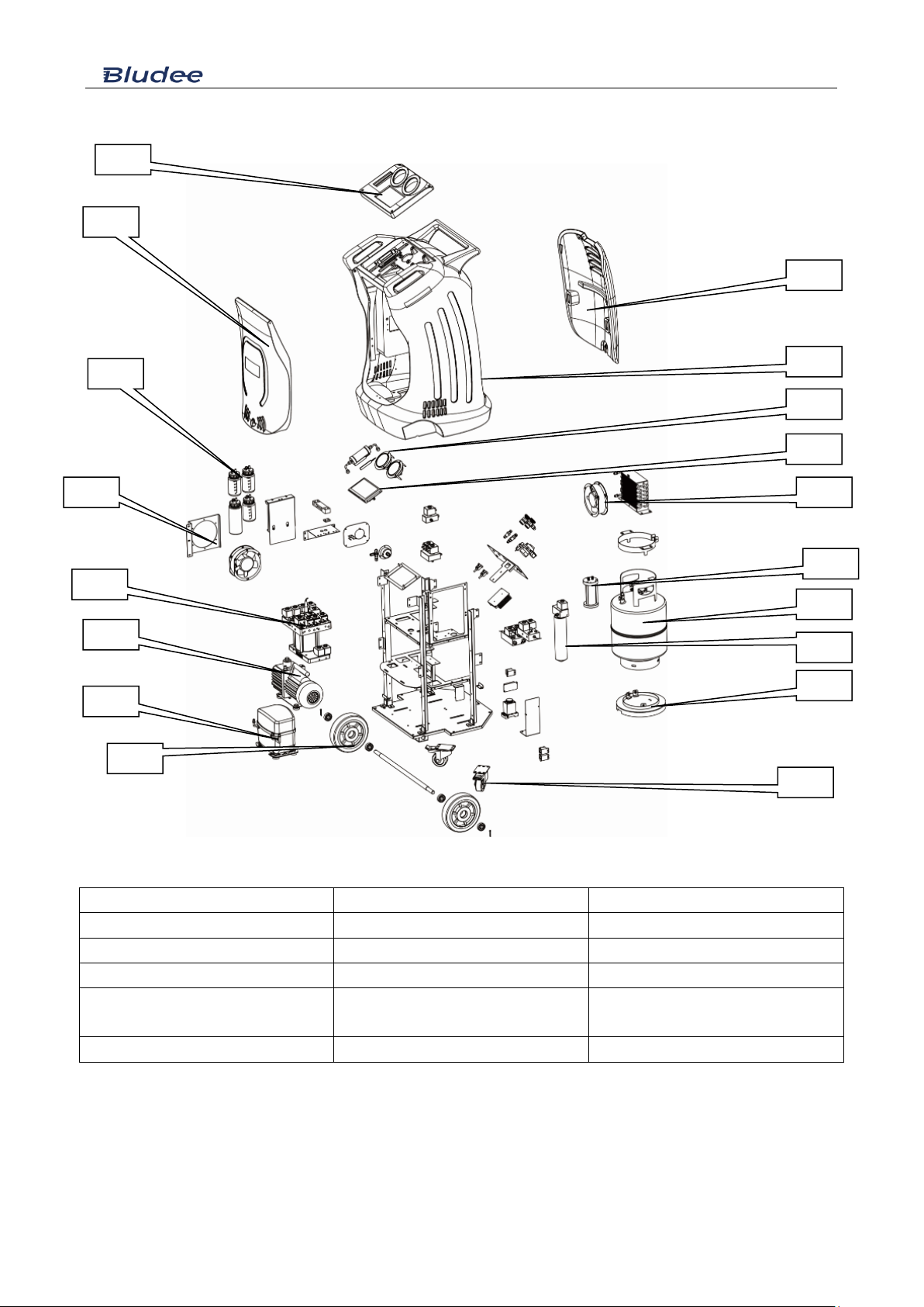
Component identification
1)Panel
2)Front cover
3) Oil vessels
4)Ventilation fan
5)Manifold and solenoid assembly
6)Vacuum pump
7)Compressor
8)Front wheel
9)Rear wheel
10) Gas tank support
11)Filter-drier
12)Gas storage tank
13)Oil accumulator (flush oil
accumulator)
14)Condenser & fan
15)LCD display
16)Manometers
17)Plastic housing
18)Rear cover
1
2
3
4
5
6
7
8
9
10
11
12
13
14
15
16
17
18
AC800 V2.00
5/16
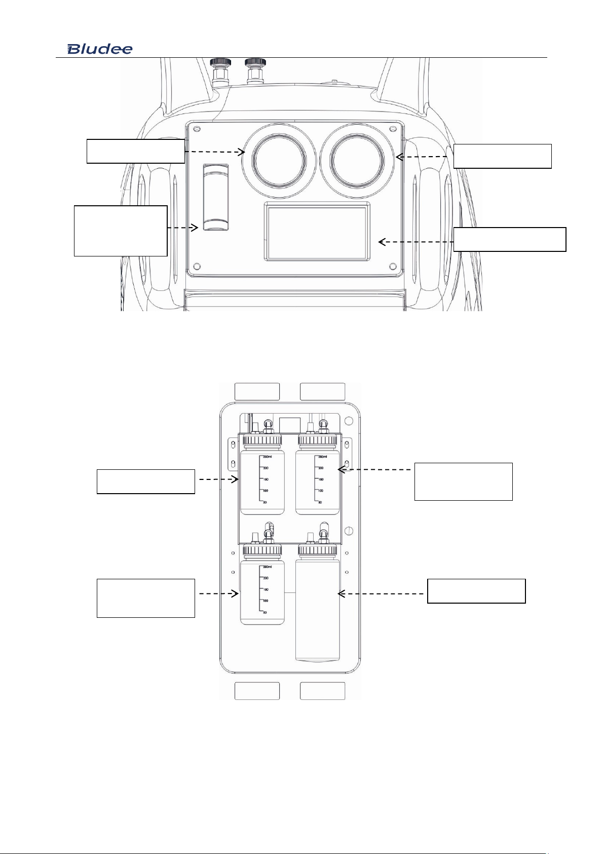
Front View, upper part (Control panel)
Left view, lower part
Sight glass
(Machine with flush
only)
High side manometer
Low side manometer
LCD screen and keypad
New PAG vessel
Used oil vessel
UV dye vessel
(Optional)
New PAG vessel
(Optional)

AC800 V2.00
6/16
Left View, upper part (Manual air purge version, basic)
Left View, upper part (Automatic air purge version, optional)
Back View, upper part
Thermal printer
Air purge valve
Tank manometer
Refrigerant hoses &
fitting (HP/LP)
Power switch
Fuse
USB update port

AC800 V2.00
7/16
Function description
Main functions
Recovery
Recovers and purifies refrigerant from automotive A/C system and it is
then stored in to the machine internal storage cylinder for re-use.
Evacuation
Removes air, debris and moisture from the vehicle A/C system, with
electronic vacuum leak detection test as optional function.
Oil/dye injection
Electronically injects the preset or selected amount of oil and/or dye
into the vehicle A/C system.. UV dye injection is optional.
Charging
Electronically charges the selected amount of refrigerant in to the
vehicle A/C system
Tank fill
Transfers liquid refrigerant from an external cylinder to the machine
internal storage cylinder.
Flushing (optional)
With this unique flushing system, the machine will extract all
compressor oil from the automotive A/C system. Since A/C additives
(such as UV dye, leak stopper and cooling booster) and contaminants
(moisture, metal and rubber particles etc.) are mainly mixed or
dissolved in compressor oil, the flush is very important not only for
A/C routine maintenance, but also necessary when an A/C part is
replaced.
Fully automatic function
selection
The machine will perform all the selected functions in a fully automatic
sequence. The machine will stop automatically once all the selected
functions or functions have been completed.
System. settings
Language
Selecting language.
Calibration
Calibrate refrigerant cylinder load cell, oil vessels load cells, pressure
transducer and temperature sensor.
Vehicle database
The machine stores a large number of vehicle makes and models, with
manufacturers’ recommended refrigerant and oil charge quantities.
Unit settings
Selecting metric or imperial units of measurement.
All sensor values displayed in this interface for equipment diagnosis
purpose.
Tare weight setting
Set empty refrigerant cylinder or refrigeration oil zero (tare) weight.

AC800 V2.00
8/16
Preparations before operation
1. Unlock tank load cell
Unlock the load cell by removing the safety locking bolt as shown below and save the bolt for future use.
PLEASE NOTE, whenever transporting the machine, re-fit the safety locking bolt to avoid damage to the load
cell.
2. Tank fill
Use the adaptor fitting, to connect either HP or LP service hose (red or blue) to the external refrigerant cylinder
liquid port which you will be transferring the refrigerant from. If the refrigerant cylinder has only,
One valve and one port, invert the cylinder as shown below. If the cylinder has,
Two valves one port, leave the cylinder upright and open the liquid valve only, if the cylinder has,
Two valves and two ports, connect the adaptor to the liquid port, leave the cylinder upright and open the liquid
valve on the cylinder. Set the amount of refrigerant to be transferred into the machine storage cylinder, once the
selected amount of refrigerant has been transferred, the machine will instruct the technician to close the liquid
valve on the external cylinder. The machine will then recover the remaining refrigerant in the service hose which
is connected to the transfer cylinder and it will then stop automatically. For more details, please refer to “tank fill”
in the operating procedure chapter.
3. Non-condensable purge
If your machine is not equipped with an automatic air purge, you will find a manual air purge valve at the
equipment side, (with reference to chapter “Component identification”). Please refer to Pressure-temperature
chart and tank pressure, turn the valve purge the non-condensable till proper pressure is obtained in the tank.

AC800 V2.00
9/16
Operating procedure
Recovery function
For the HFO-1234yf system, refrigerant identification is necessarily processed. Only when the purity of
refrigerant is above 98% the recovery is allowed.
Check and empty the used oil vessel before the recovery process is initiated.
The recovery process removes refrigerant from the vehicle A/C system, until a vacuum is reached. During this
process, the refrigerant is purified from any moisture, oil, and foreign particles. The processed refrigerant is then
stored in the internal storage cylinder of the machine, ready for re-use. If any oil is recovered during this process,
the oil will be discharged into the used oil vessel. After the first recovery has been completed, the machine will
pause for 3 minutes, to check if there is any refrigerant left in the vehicle A/C system. Recovery will start again
automatically if there is a pressure rise during the 3-minute pause. At the completion of recovery, the machine will
display and print the total amount of refrigerant recovered and oil if any.
Evacuation function
Select “Vacuum” , evacuation is performed to further remove air and moisture from the vehicle A/C system,
making it ready for oil injection. Evacuation time can be set from 2 to 60 minutes. If the machine has vacuum leak
test function, vacuum test can be selected to effect 10-minute vacuum leak test.
Oil injection function
Select “Oil injection”, set oil volume and new oil is sucked into A/C system by vacuum created by vacuum
function.
UV can be also selected to inject UV dye for future leak detection.
If the vehicle A/C system is not in a vacuum state, oil or dye injection cannot be performed and the machine will
display a warning.
Hose flush, if hose flush is selected (highly recommended), the process will flush the oil from the wall of the
service hoses and internal pipelines, to make sure the new oil to be injected is not contaminated with the previous
oil injected. This process will take about 5 minutes.

AC800 V2.00
10
/16
Refrigerant charging function
Refrigerant charge amount can be set by the technician, or by selecting car make and model in the database.
Refrigerant can be charged through the high side, low side, or high and low side.
Note, vehicle A/C system should be switched on when charging through the low side of the vehicle A/C system.
Note, if charging is selected from the high and low sides simultaneously, care must be taken. After charging
function is completed and before starting the engine and switching on the A/C system, turn the compressor hub
several times by hand to expel any liquid refrigerant that may have accumulated in the compressor compression
chambers during the charging process. Not performing this process can damage or destroy the compressor.
Hose purge, hose purge is selected in charge function (default), to charge the full amount of refrigerant selected.
Some refrigerant will be left in the discharge hose (high side service hose) either at charge function or at A/C
diagnosis with vehicle A/C on. Follow the instruction displayed on the touch screen to purge the remainder of
refrigerant left in the discharge hose into the vehicle A/C system. This will make certain that 100% of the selected
amount of refrigerant is fully charged into the vehicle A/C system.
Tank fill
Please note, refrigerant identification is highly recommended before transferring refrigerant into
the machine's internal storage cylinder, by using a reliable refrigerant identifier.
Select Tank fill to fill or add refrigerant into a machine storage cylinder. It is recommended to maintain 4-6 kg
refrigerant in the machine internal cylinder at all times, to guarantee better charging and flushing operations.
During the refrigerant cylinder filling process, the machine will display to the technician to close the hand valve
on the external cylinder, and the machine will then recover the rest of refrigerant which is left in the transfer
service hose and internal pipelines.
The minimum tank fill set value is 0.5kg.
The maximum tank fill set value is the calculation result of 8kg (80% of tank allowable maximum weight) minus
the amount of refrigerant the tank contains (For example, if there is 2kg refrigerant in the equipment tank, the
maximum tank set value is 6kg).

AC800 V2.00
11
/16
Flushing function (COR, Compressor Oil Recovery, Optional)
For HFO-1234yf system, refrigerant identification is necessarily processed. Only when the purity of refrigerant
is above 98% the recovery is allowed.
Please note, empty used oil vessel before starting this operation.
Flushing function is performed to completely extract compressor oil from A/C system, thus contaminants such as
acidified substances, moisture and other foreign particles will also be extracted together with oil.
During the flush, refrigerant flows in the forward direction (charge liquid refrigerant from A/C low side to
dissolve compressor oil, and at the same time recover from the high side) and reverse direction (reverse direction
means charge from the high side and recover from the low side, in reverse from normal A/C flow), each direction
lasts certain period of time. Flush time can be set corresponding to refrigerant amount in system. For example,
A/C system with 500g refrigerant, flush time is recommended to be set at 30 minutes, while 60 minutes can be
set for system with 1kg or more refrigerant. Flushing refrigerant will be recovered and purified automatically, at
the end of the flushing process and stored in the storage cylinder, ready for re-use.
For some A/C system equipped with evaporator solenoids or electronic expansion valves, which are normally
closed when the vehicle A/C is off, it is recommended to activate the solenoid and TX valves with proper
diagnostic scanner or remove and bridge these valves with the appropriate bridging fittings. Not performing the
above, refrigerant flow is restricted and flushing efficiency can be affected.
For a multi-flow condenser, the oil in the condenser may not be flushed out completely.
Note: Each flush will cause about 200g refrigerant loss.
Remarks: As one of the innovative technologies created by BLUDEE, COR offers a new method of automotive
A/C maintenance and may highly reduce A/C repetitive repair rate. Please consult BLUDEE professionals to
get more technical tips for flushing.
Automatic function mode
Please note, empty used oil vessel before starting this operation.
In automatic function mode, the machine runs flush, recovery, evacuation, vacuum test if selected, oil injection,
dye injection and refrigerant charge in sequence, with data of each operation preset by the technician.

AC800 V2.00
12
/16
System Setting
Input password 111111 to enter “System. Setting”. In system setting, Language, Calibration, Database, Unit set,
Empty container weight set, Component testing and owner information will be displayed or reconfigured.
Calibration: Even though the machine is equipped with calibration weight for quick and easy calibration, it is
recommended to have a professional technician only to perform calibration of load cells, pressure transducer, and
temperature sensor.
Warning: Not calibrating the machine correctly can have serious consequences on the machine and/or vehicle
A/C system.
Database: The technician can access the database of refrigerant, oil volume of different car makes and models.
Record: Record total operations of recovery, vacuum, oil injection and charge. Can reset to re-record. A dynamic
code is needed for access.
Unit settings: To set metric or imperial unit of measurement. In the interface of “unit set”, values of each sensor
of the equipment are displayed for equipment diagnosis purpose.
Empty container weight set:
The total load cell reading equals the sum of empty container weight and net refrigerant/oil content value. Thus,
increase/decrease empty container weight, can correspondingly decrease/increase refrigerant/oil value displayed
in the main operation interface.
Component test:
The technician can activate and deactivate different electrical components of the machine. This is for quick and
easy diagnosis and troubleshooting.
Please note:
Only qualified technician (with special password) is allowed to access this function, not performing this test
correctly could cause damage to the machine or injury to the operator.

AC800 V2.00
13
/16
Caring for your equipment
●Keep your equipment clean and well maintained at all times.
●Keep service hoses stored on the storage adapters when not in use, to avoid dirt and dust
contaminating the internals of the couplers which will then end-up in the vehicle A/C system, which
can cause serious system malfunction.
●Always clean vehicle A/C system service ports before connecting machine quick couplers on to
the service ports.
●Keep the system stored in a clean area and away from direct sunlight and artificial heat source,
when not in use.
●Perform regular services on the system as recommended by the manufacturer. Ignoring and
skipping services will deteriorate the integrity of the machine.
●If the machine is used on badly contaminated A/C systems frequently, it is recommended that
more frequent vacuum pump oil changes are made, and main filter replacements are performed.
Contaminated vacuum pump oil will cause the internal corrosion of the vacuum pump, which
eventually will cause the failure of the vacuum pump. A contaminated main filter will decrease the
refrigerant purity.
●Do not bump or move the machine when the technician is in the process of charging a vehicle,
this can affect the charging accuracy.
●If the machine is bumped or knocked down accidentally, make calibration again and check for
possible leaking.
●DO NOT use compressed air to test for leaks.
●If the technician is not sure about the correct way of operating the machine, please do not
hesitate to contact your distributor or manufacturer. We always like to help you.

AC800 V2.00
14
/16
Software update
Pressing and keys, turn on the
machine.
The machine displays the following message.
Connect the machine with PC through USB port. In
PC, run USBload.exe, the PC displays the following
message:
Click “OpenFile”to select update to update, e.g. file
“AC800_V2.01”(for main program update) or
“Database_V2.02”(for database update). Then click
“Connect”the PC displays the following message
Click “Program_load”for main program update, or
click “Database_load”for database update, the
machine displays the following:
In about 1 minute, the machine displays:
Turn off the machine and turn it on again, the machine
will run the updated software.
AC800 V2.00
15
/16
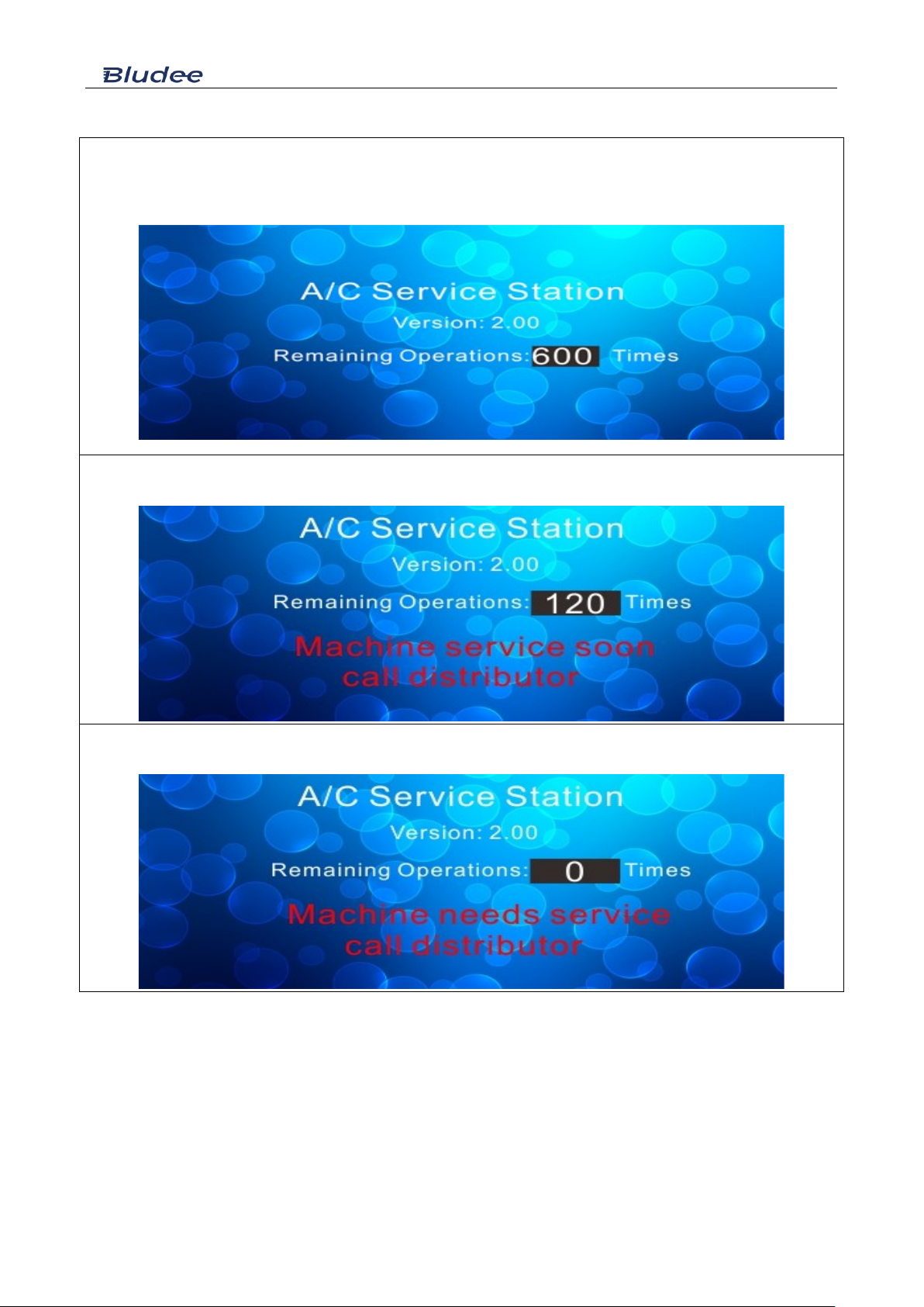
Maintenance remaining counter
The machine permits totally 600 operations (every recovery or vacuum counts for 1 operation, and one automatic
operation counts for 2 operations) before service/maintenance is forced to make. The remaining operation number
is displayed when machine turns on.
Upon 480 operations having been made, the machine displays the following message, and users can continue
using the equipment meanwhile make distributor appointment
Upon 600 operations having been made, the machine will display the following message while the machine stops
working. Maintenance has to be made to reset service interval time again.

AC800 V2.00
16
/16
Packing list
Part Number
Article
pcs
Package
ZT010048
AC800 main unit
1
BZ030017
3m red service hose
1
BA030016
3m blue service hose
1
BZ130037
HP quick coupler
1
BZ130038
LP quick coupler
1
DZ160033
30A fuse
1
DZ180034
Update cable with USB
1
WJ010007
HP/LP block cap
2
BZ130026
Tank fill fitting (R134a)
1
BZ130027
Tank fill fitting (R1234yf)
1
Table of contents


