%
(Drawing15)
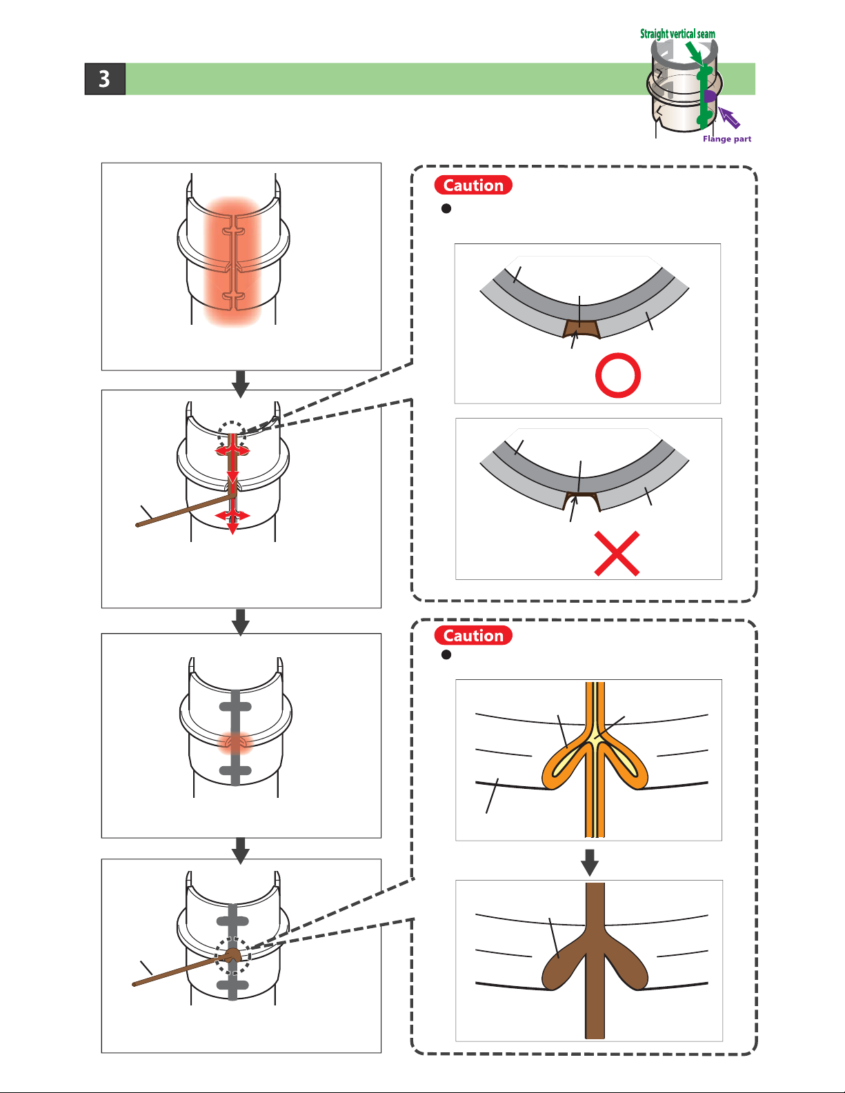
Entire circumference
of bottom edge
Apply the filler rod to the weld area
clockwise and counterclockwise to ensure
that the gap is completely filled with brazing
material.
Braze entire circumference of bottom edge.
(Drawing 15)
Pipe Support
Ferrule
Copper pipe
Brazing material
Ensure that entire surface of weld area
is properly heated.
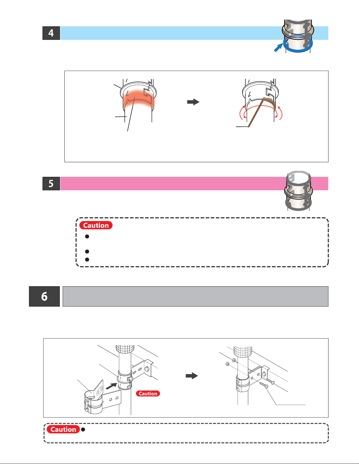
Check brazing condition again after completion of
brazing work.
Check for integrity of brazing material on all brazed surfaces of ferrule.
Cool down brazed ferrule assembly with damp cloth.
Filled brazing material may flow downwards when heat is applied to an adjacent section,
In this case, rebraze affected part.
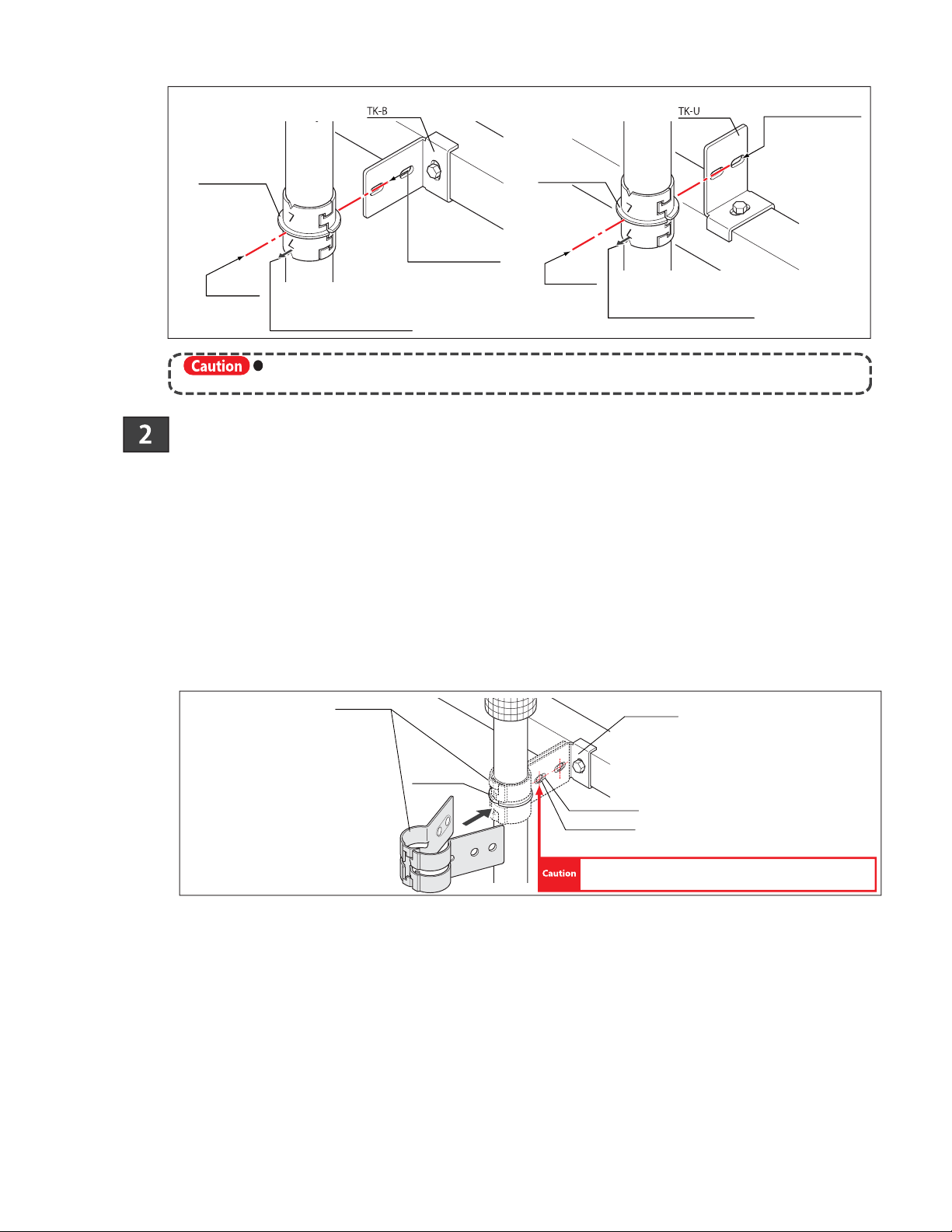
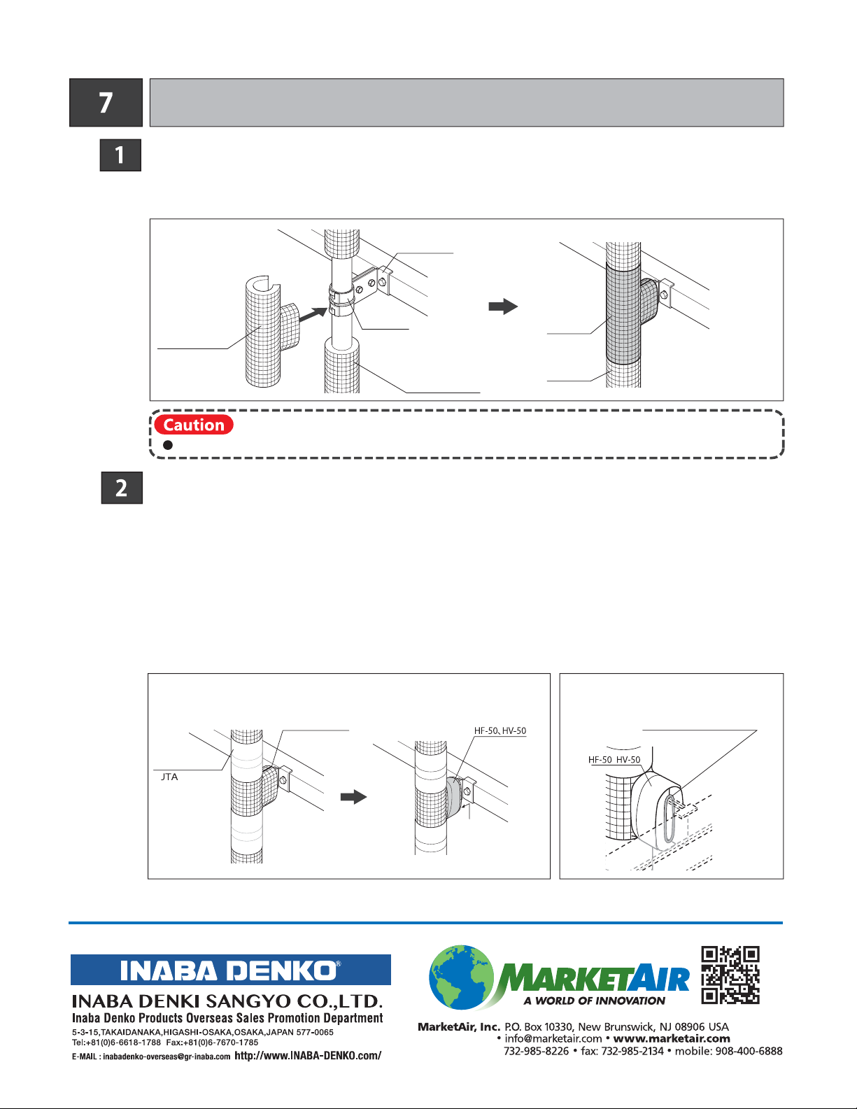
After cooling ferrule, attach fixing clamp around ferrule and attach
to mounting bracket (drawing 16).
Pipe Support Ferrule
(Drawing16)
IF fixing clamp is attached to ferrule before it is sufficiently cooled, damage to painted
surface of clamp may occur.
Confirm that pipe ferrule has cooled down
sufficiently after brazing. M6 bolt enclosed
Fixing Clamp
& '()
& '()& '()
"#