Blue Diamond Mini Skid Steer 2 Series User manual
Operation and Maintenance Manual
Mini Skid Steer
Series 2 Brush Cutter
888-376-7027 | BlueDiamondAttachments.com
Register your
WARRANTY
within 30 days
of purchase

Blue Diamond® Attachments2
Thank you for your decision to purchase a Blue Dia-
mond® Mini Skid Steer Series 2 Brush Cutter To ensure
maximum performance of your equipment, it is manda-
tory that you thoroughly study the Operator’s manual
and follow the recommendations. Proper operation and
maintenance are essential to maximize equipment life
and prevent personal injury.
Operate and maintain this equipment in a safe man-
ner and in accordance with all applicable local, state,
and federal codes, regulations and /or laws. Follow all
on-product labeling and instructions.
Make sure that all personnel have read this Operator’s
Manual and thoroughly understand safe and correct
operating, installation and maintenance procedures.
Blue Diamond is continually working to improve its
products. Blue Diamond reserves the right to make any
improvements or changes as deemed practical and pos-
sible without incurring any responsibility or obligation
to make any changes or additions to equipment sold
previously.
Although great care has been taken to ensure the
accuracy of this publication, Blue Diamond makes no
warranty or guarantee of any kind, written or expressed,
implied or otherwise with regard to the information
contained within this manual. Blue Diamond assumes
no responsibility for any errors that may appear in this
manual and shall not be liable under any circumstances
for incidental, consequential or punitive damages in con-
nection with, or arising from the use of this manual.
Keep this manual available for frequent reference. All
new operators or owners must review the manual before
using the equipment and annually thereafter. Contact
your Blue Diamond Attachments Dealer for assistance,
information, or additional copies of the manual. Contact
www.bluediamondattachments.com or call 888-376-
7027 for a complete list of dealers in your area.
Serial Number Location:
Please record attachment information in the space pro-
vided for future reference.
Model Number:_____________________________
Serial Number: _____________________________
Dealer Name: ______________________________
Dealer Number:_____________________________
Date of Purchase:___________________________
The serial number plate is located on the deck brace.
Always use your serial number when requesting infor-
mation or when ordering parts.
NOTE: The directions left, right, front and rear, as
mentioned throughout this manual, are as viewed from
the operator’s position.
Introduction: Owner Information
Revision Date: 11.27.2023

3Blue Diamond® Attachments
Table of Contents
1. Introduction......................................................................................4
1.1 Attachment Identification.........................................................4
1.2 Attachment Model Numbers..................................................4
2. Safety ...........................................................................................5-8
2.1 General Safety Information.................................................... 5
2.2 Operators.................................................................................. 6
2.3 Safety Guidelines.....................................................................7
3. Operation .................................................................................. 9-15
3.1 Attachment Inspection Guidelines ....................................... 9
3.2 Entering & Exiting the Prime Mover....................................11
3.3 Attachment Installation..........................................................11
3.4 Operating the Attachment ................................................... 13
4. Maintenance ...........................................................................16-20
4.1 Service Schedule ....................................................................16
4.2 Drive Assembly ...................................................................... 17
4.3 Blade Assembly...................................................................... 18
4.4 Cleaning the Attachment .....................................................18
4.5 Troubleshooting .....................................................................19
5. Parts.........................................................................................20-26
5.1 Parts Breakdown ....................................................................20
5.2 Mount Options.......................................................................22
5.3 Hose Set ................................................................................. 23
5.4 Drive Assembly ..................................................................... 24
5.5 Blade Carrier..........................................................................25
5.6 Decal Identification & Location..........................................26
6. Specifications ........................................................................27-28
6.1 Attachment Specifications ................................................... 27
6.2 Torque Specifications ..........................................................28
7. Warranty ........................................................................................29

Blue Diamond® Attachments4
1. Introduction
1.1 Attachment Identification
H M
C
M S 2 B C M M N
W F F
36” closed 9 – 20
GPM
Mini Universal 303716-25
Bobcat MT compatible 303716-26
Avant compatible 303716-35
42”
open 12 – 20
GPM
Mini Universal 303728-25
Bobcat MT compatible 303728-26
Avant compatible 303728-35
closed 12 – 20
GPM
Mini Universal 303722-25
Bobcat MT compatible 303722-26
Avant compatible 303722-35
50” closed 10 – 20
GPM
Mini Universal 303731-25
Bobcat MT compatible 303731-26
Avant compatible 303731-35
M
P
S P
C C
(closed front only)
H S
1.2 Attachment Model Numbers
5Blue Diamond® Attachments
2.1 General Safety Information Operating Safety
• Read and follow instructions in this manual
and the machine’s Operators Manual before
operating.
• The manual must always remain with the
machine. In case of loss or damage, request
a new copy from your dealer or from Blue
Diamond.
• Strictly follow all rules prescribed by the safety
pictograms/decals applied to the machine.
Ensure that all safety pictograms/decals are
legible. If pictograms/decals are worn, they
must be replaced with new ones obtained
from Blue Diamond and placed in the position
indicated by this manual.
• Before using the machine, make sure that
all safety devices are installed and in good
working conditions. In case of damage or
shields, replace them immediately.
• It is absolutely forbidden to remove or alter
safety devices and/or safety precautions
• Pay maximum attention to avoid any accidental
contact with rotating parts of the machine.
• If the use of the machine is required at night
or in conditions of reduced visibility, use
the lighting system of the prime mover and
possibly an auxiliary lighting system.
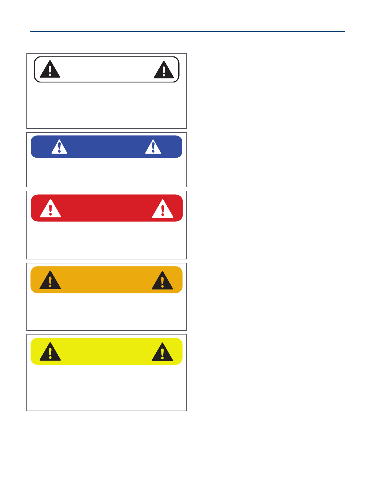
2. Safety
CAUTION
The signal word CAUTION on the machine and
in the manuals indicates a potentially hazardous
situation which, if not avoided, may result in minor
or moderate injury. It may also be used to alert
against unsafe practices.
WARNING
The signal word WARNING on the machine and
in the manuals indicates a potentially hazardous
situation which, if not avoided, could result in
death or serious injury.
DANGER
The signal word DANGER on the machine and
in the manuals indicates a hazardous situation
which, if not avoided, will result in death or serious
injury.
SAFETY ALERT SYMBOL
This SAFETY ALERT SYMBOL identifies important
safety messages on the equipment and in the
owner’s manual. When you see this symbol, be
alert to the possibility of personal injury and
carefully read the message that follows.
IMPORTANT
The signal word IMPORTANT identifies
procedures which must be followed to avoid
damage to the machine.
Blue Diamond® Attachments6
2.2 Operators
Qualified Operators
The operator is a person suited to the work and
who is physically and psychologically able to
withstand the demands connected with operating
the equipment for its intended use. The operator
must not allow anyone to approach the machine
while it is working and must not allow external
personnel to operate the machine or attachment.
He is to follow the given instructions in this
manual and the machine operator’s manual in
order to obtain maximum performance, minimum
consumption, and maximum safety for himself and
for others.
The operator is responsible for scrupulously
observing all the instructions given in this manual.
Operator Training
• Check the rules and regulations at your
location. The rules may include an employer’s
work safety requirements. Regulations may
apply to local driving requirements or use
of a Slow Moving Vehicle (SMV) emblem.
Regulations may identify a hazard such as a
utility line.
• The new operator must start in an area without
bystanders and use all the controls until he or
she can operate the machine safely under all
conditions of the work area.
Operator Safety
• Before starting, and during operation of the
attachment, make sure there are no people
or animals in the operation area; the machine
can project material from the back with risks of
serious injury or death.
• During operation, adjustment, maintenance,
repairing, or transportation of the machine, the
operator must always use appropriate Personal
Protective Equipment (PPE) including but not
limited to safety glasses, working gloves, dust-
mask, safety helmet, and hearing protection.
• Do not operate the attachment or machine
while wearing loose fitting clothing that can be
entangled or caught in parts of the machine.
• Do not operate the implement when tired, not
in good condition, or under the influence of
alcohol or drugs.
2. Safety
AVOID SERIOUS INJURY OR DEATH
Operators must receive instructions before
operating the machine. Untrained operators can
cause serious injury or death.
For an operator to be qualified, he or she must
not use drugs or alcoholic drinks which impair
alertness or coordination while working. An
operator who is taking prescription drugs must
get medical advice to determine if he or she can
safely operate a machine and the equipment.
For an operator to be qualified, he or she must
have read and understood the instructions of this
manual, he or she must make adequate preparation
for the proper use of the machine, and he or she
must hold a driving license.
In case of doubt regarding the use of the machine
and/or the interpretation of this manual, the operator
must contact either their dealer or Blue Diamond.
DANGER

7Blue Diamond® Attachments
2.3 Safety Guidelines
Operating Safety
• Read and follow instructions in this manual
and the machine’s Operator’s Manual before
operating.
• Under no circumstances should young children
be allowed to work with this equipment.
• This equipment is dangerous to persons
unfamiliar with its operation.
• Check for overhead and / or underground lines
before operating equipment (if applicable).
• In addition to the design and configuration
of equipment, hazard control and accident
prevention are dependent upon the
awareness, concern, prudence and proper
training of personnel involved in the operation,
transport, maintenance and storage of
equipment.
• Check that the attachment is securely fastened
to the machine.
• Make sure all the machine controls are in the
NEUTRAL before starting the machine.
• Operate the equipment only from the
operator’s position.
• Operate the equipment according to the
Operator’s Manual.
• When learning to operate the equipment, do it
at a slow rate in an area clear of bystanders.
• DO NOT permit personnel to be in the work
area when operating the equipment.
• The equipment must be used ONLY on
approved machines.
• DO NOT modify the equipment in any way.
Unauthorized modification may impair the
function and / or safety and could aect the life
of the equipment.
• DO NOT make any adjustments or repairs on
the equipment while the machine is running.
• Keep shields and guards in place. Replace if
damaged.
• DO NOT operate equipment in poor visibility
conditions such as fog, darkness, or any
conditions that limit clear visibility less than
300 feet (100 m) in front of and to the sides of
the equipment.
• When conditions make it necessary to slow
ground speed, shift to a lower gear rather
than reducing engine speed. The engine will
maintain rated speed and keep cutter running
at optimum cutting speed.
• DO NOT operate in a work area that has
not been inspected for foreign debris and
obstacles.
• Remove any foreign objects and clearly mark
any objects that cannot be removed.
• Wear face shield, hard hat, gloves, hearing
protection, and other protective clothing when
required.
2. Safety

Blue Diamond® Attachments8
Machine Requirements and Capabilities
• The machine’s operator’s cab should be
equipped with a thermoplastic polycarbonate
or similar material front window, and similar
protection on the sides of the operator’s cab
before operating the equipment.
• Keep bystanders clear of moving parts and the
work area. Keep children away.
• Do Not exceed 3000 continuous PSI (206 bar)
operating pressure.
• Use caution on slopes and near banks and
ditches to prevent overturn.
Fire Prevention Safety
• Flammable debris (leaves, grass, etc.) must
be removed regularly. If flammable debris
is allowed to accumulate, it can cause a fire
hazard. Clean often to avoid this accumulation.
• The equipment’s hydraulic motor compartment
must be inspected every day and cleaned
if necessary to prevent fire hazards and
overheating.
• All fuels, most lubricants, and some coolant
mixtures are flammable. Flammable fluids that
are leaking or spilled onto hot surfaces or onto
electrical components can cause a fire.
Transporting Safety
• Comply with state and local laws governing
highway safety and movement of machinery on
public roads.
• Check local laws for all highway lighting and
marking requirements.
• Always yield to oncoming trac and move to
the side of the road so any following trac may
pass.
• Never allow riders on either machine or
equipment.
• If transporting the equipment on a truck or
trailer, make sure the equipment is properly
secured to the transport vehicle.
Hydraulic System
• Check hydraulic tubes, hoses and fittings for
damage and leakage. Never use open flame
or bare skin to check for leaks. Hydraulic tubes
and hoses must be properly routed and have
adequate support and secure clamps. Tighten
or replace any parts that show leakage.
• Always clean fluid spills. Do not use gasoline or
diesel fuel for cleaning parts. Use commercial
nonflammable solvents.
Personal Protective Equipment
2. Safety
Proper Work clothes: To help ensure your
safety as a designated operator wear
proper work clothes including tight fitting
clothes, protective gloves and shoes.
Safety Helmet: To help ensure your
safety as a designated operator wear
a safety helmet.
Protective Shoes: To help ensure your
safety as a designated operator wear
protective shoes.
Hand Protection: To help ensure your
safety as a designated operator wear
protective gloves.
Eye/Ear Protection: To help ensure your
safety as a designated operator wear a
safety helmet and eye/ear protection.
9Blue Diamond® Attachments
3.1 Attachment Inspection
Guidelines
Pre-Operation Inspection
Before operating the Mini Series 2 Brush Cutter
for the first time and each time thereafter, use
the following list as a guideline during equipment
inspection.
• Fully clean the attachment. See section 4.4
“Cleaning the Attachment” on page 18.
• Lubricate the attachment per the schedule
outline in the Maintenance Section. See
section 4.1 “Service Schedule” on page 16.
• Check the brush cutter mounting plate for
damage. Check for loose or missing parts.
Repair as needed before operation.
• Check that blades are in good condition.
Sharpen or replace them, if necessary.
• Check that all shields and guards are in place.
• Check for loose bolts and tighten them if
necessary.
• Check all welds on the attachment for wear
and damage each time the attachment is
removed from this machine.
• Check for damaged or missing safety decals.
Replace if necessary.
• Inspect the machine’s mounting frame. (See
the machine’s Operator’s Manual for inspecting
the mounting frame). Replace any parts
that are damaged, bent or missing. Keep all
fasteners tight. Look for cracked welds.
• Check condition of all hydraulic components
for leaks. Repair as required.
NOTE: Do not operate with hydraulic leaks.
• Verify that the brush cutter is properly
connected to the machine.
3. Operation
WARNING
AVOID SERIOUS INJURY OR DEATH
• Disengage machine’s auxiliary hydraulics,
engage the machine’s parking brake, stop the
engine and make sure all rotating components
are completely stopped before connecting,
disconnecting, adjusting, or cleaning
equipment.
• Always keep shields and all guards in place
when using the equipment.
• Disengage machine’s auxiliary hydraulics for
road travel.
• Keep hands, feet, and clothing away from
rotating parts.
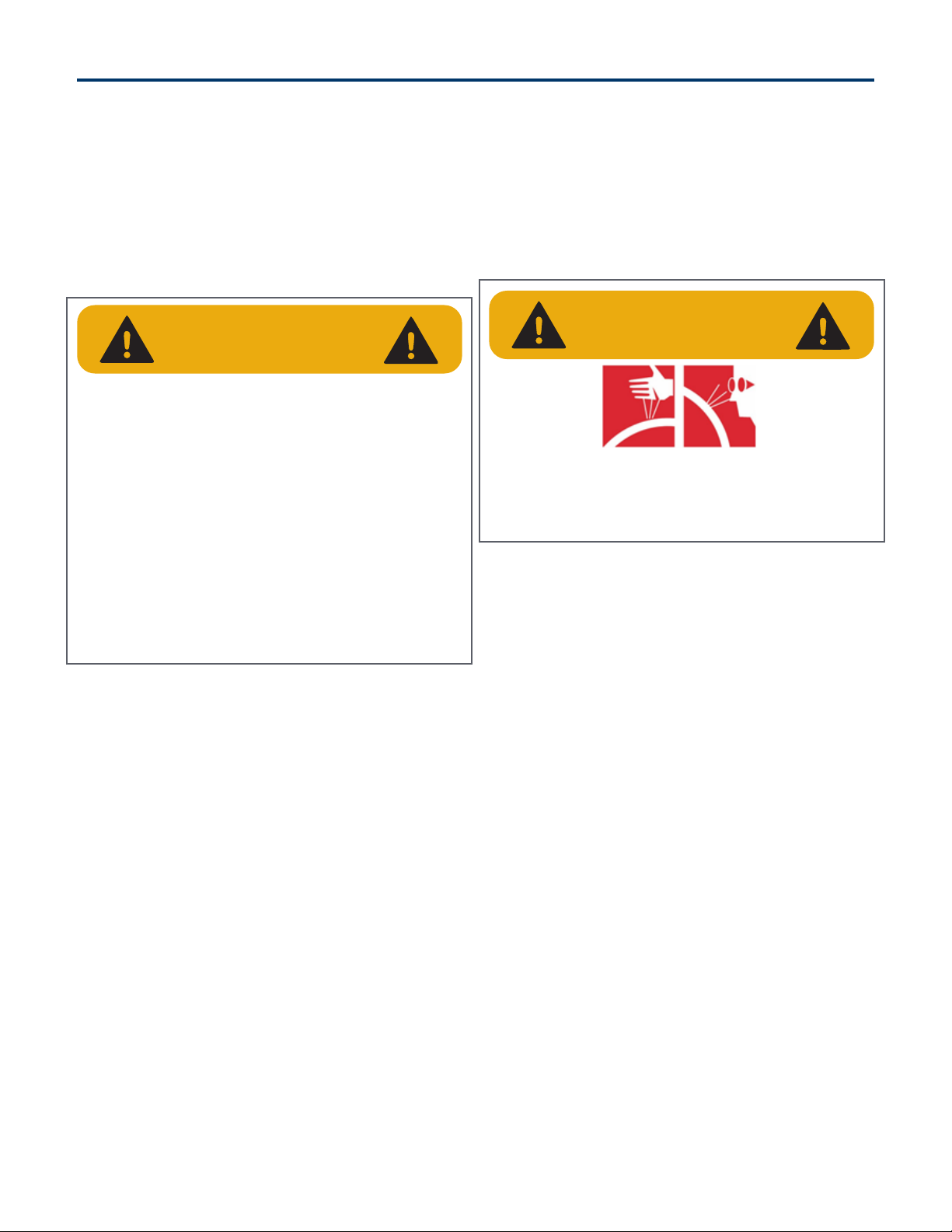
WARNING
Leaking fluids under pressure can enter the skin
and cause serious injury or death. Immediate
medical attention is required.
Wear goggles. Use cardboard to check for leaks.

Blue Diamond® Attachments10
3.1 Attachment Inspection
Guidelines Cont’d
Daily Inspection
NOTE: Inspect the attachment by performing a
walk around daily before and after use. Use the
following inspection checklist as a guideline.
Check the following items every 10 hours of
operation:
• Verify that the brush cutter is properly
connected to the machine.
• Check that all shields and guards are in place.
• Check hydraulic lines, connections, and
fittings for hydraulic oil leaks. Repair or replace
damaged parts if necessary.
• Check the brush cutter mounting hardware for
wear or damage. Inspect the pins and mount
(on the attachment) for wear or damage. Repair
or replace damaged parts if necessary.
Weekly Inspection
Check the following items every 40 hours of
operation:
• Check blade bolts for correct torque 1440 ft/lb
(1952 N•m).
• Check all bolts for tightness (see Section 6.2
“Torque Specifications” on page 28).
• Inspect the deck for cracks, bends, or damage.
Monthly Inspection
• Inspect the blades for cracks, bends, or
excessive wear.
• Check the skid plates for wear.
• Check that all bolts are tight.
• Check blades and mounting plate for cracks or
damage. Replace if necessary.
• Check blade mounting hardware for correct
torque 1440 ft/lb (1952 N•m). Check mounting
plate hardware.
• Check deck, shields, and guards. Repair if
damaged or replace if necessary.
• Check for damaged or missing decals. Replace
if necessary.
• Check for damaged or leaking hydraulic hoses
or fittings. Replace if necessary.
• Clean all debris, leaves, grass, and flammable
material from deck area and under covers.
• Lubricate as required.
3. Operation
WARNING
AVOID SERIOUS INJURY OR DEATH
• Always park on a flat level surface.
• Lower and place attachment flat on the ground.
• Place all controls in NEUTRAL.
• Engage the park brake.
• Stop the engine and remove the key.
• Wait for all moving parts to stop.
SEE MACHINE’S OPERATOR’S MANUAL FOR
ADDITIONAL INFORMATION.
11Blue Diamond® Attachments
3.2 Entering & Exiting the
Prime Mover
Entering the Operator’s Position
When in the operator’s position, start the engine
and release the parking brake.
See the mini skid steer operator’s manual to
correctly operate the machine.
Leaving the Operator’s Position
Park the machine/attachment on a flat level
surface.
Place all controls in neutral, engage the park
brake, stop the engine and wait for all moving
parts to stop. Leave the operator’s position.
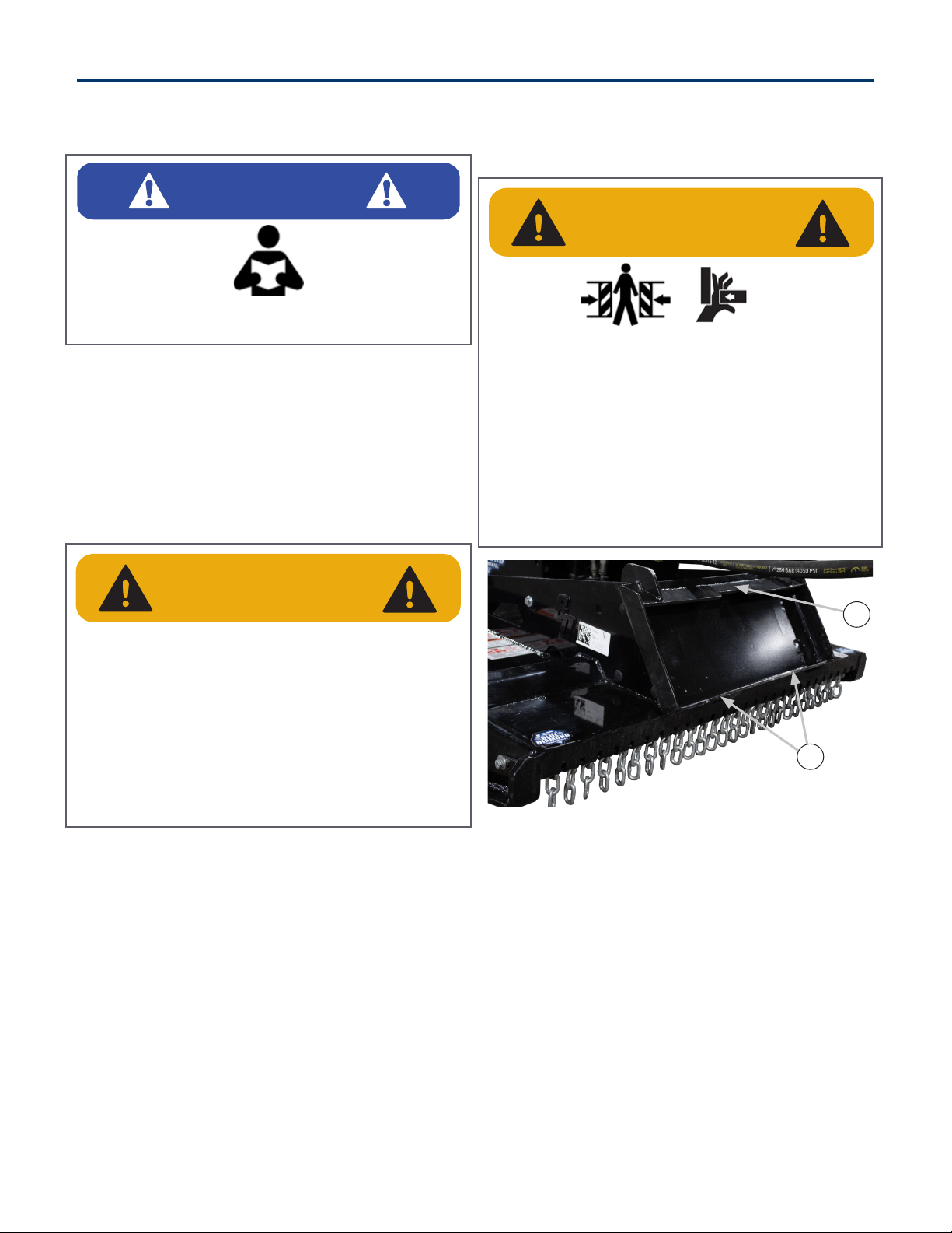
3.3 Attachment Installation
Connecting Attachment To The Machine
Figure 1
Inspect the brush cutter’s mounting flange (Item 1),
wedge mounts (Item 2) [Figure 1], mount hardware,
and all welds for wear or damage each time the
brush cutter is removed from the machine.
Before connecting to the attachment, inspect the
machine’s mounting plate. (See the machine’s
Operator’s Manual for inspecting the mounting
frame).
3. Operation
IMPORTANT
See the machine’s Operator’s Manual for detailed
information on operating the loader.
WARNING
CRUSH HAZARD
• Before moving the machine, look in all
directions and make sure no bystanders,
especially small children are in the work area.
• Do not allow anyone between the machine
and attachment when approaching the
attachment for connecting.
• Keep fingers and hands out of pinch points
when connecting and disconnecting the
attachment.
WARNING
AVOID SERIOUS INJURY OR DEATH
• Always park on a flat level surface.
• Lower and place attachment flat on the ground.
• Place all controls in NEUTRAL.
• Engage the park brake.
• Stop the engine and remove the key.
• Wait for all moving parts to stop.
SEE MACHINE’S OPERATOR’S MANUAL FOR
ADDITIONAL INFORMATION.
2
1

Blue Diamond® Attachments12
3.3 Attachment Installation
Cont’d
Connecting Attachment to the Machine
Cont’d
Enter the operator’s position. See “Entering the
Operator’s Position” on page 11.
Drive the machine slowly forward, until the top
edge of the machine’s mounting plate is under the
top flange of the attachment mounting frame.
Slowly tilt the machine’s mounting plate back until
the attachment mounting frame fully contacts the
front of the machine’s mounting plate.
Leave the operator’s position. See “Leaving the
Operator’s Position” on page 11.
Engage attachment locking levers / wedges (See
the machine’s Operator’s Manual for detailed
information).
Connecting Hydraulic Hoses
Remove dirt or debris from the male and female
couplers. Visually inspect the couplers for
corroding, cracking, damage, or excessive wear.
Replace as needed.
Connect the attachment hydraulic hoses to the
machine. Pull on each hose to verify the full
connection is made.
Disconnecting Hydraulic Hoses
Relieve auxiliary hydraulic pressure. (See
the machine’s Operator’s Manual for correct
procedure.)
Disconnect attachment hydraulic hoses from the
machine.
Disconnecting Attachment From the
Machine
Relieve auxiliary hydraulic pressure. (See
the machine’s Operator’s Manual for correct
procedure.)
Park the machine and attachment on a flat level
surface. Lower the attachment flat on the ground.
Leave the operator’s position. See “Leaving the
Operator’s Position” on page 11.
Disconnect attachment hydraulic hoses from the
machine.
Disengage locking pins / wedges. (See the
machine’s Operator’s Manual for correct
procedure.)
Enter the operator’s position. See “Entering the
Operator’s Position” on page 11.
Slowly tilt the machine’s mounting plate forward
until the attachment mounting frame is free from
the machine’s mounting plate.
Drive the machine slowly backward, away from the
attachment.
3. Operation
WARNING
AVOID SERIOUS INJURY OR DEATH
The locking pins / wedges must extend through
the holes in the attachment mounting frame.
Failure to secure locking pins / wedges can allow
attachment to come o.
SEE MACHINE’S OPERATOR’S MANUAL FOR
ADDITIONAL INFORMATION.
IMPORTANT
Throughly clean the quick couplers before
making connections. Dirt can quickly damage the
hydraulic system.
WARNING
AVOID SERIOUS INJURY OR DEATH
Hydraulic fluid, tubes, fittings, and quick couplers
can get hot during operation. Be careful when
connecting and disconnecting hydraulic hoses.

13Blue Diamond® Attachments
WARNING
THROWN OBJECTS OR ROTATING BLADES CAN
CAUSE SERIOUS INJURY OR DEATH
• Clear work area of all debris, such as rope,
wire, cable or other materials that can wrap
around blade carrier and blades, causing
entanglement and attachment damage.
• DO NOT operate brush cutter in vicinity of
bystanders, animals, or damageable property.
Objects can be thrown more than several
hundred feet.
• Keep all shields installed. Repair or replace if
damaged or missing.
• Check blade carrier, blades and mounting
hardware. Replace if damaged. Never weld or
modify.
3.4 Operating the Attachment
Machine Requirements
NOTE: Exceeding maximum hydraulic flow will
over-speed the drive motor and result in motor
failure.
Operation
Travel Position
Lift the attachment 4 – 6 inches o the ground
when traveling between one side and another.
C S H
F
W
(N )
36” Cutter 9 – 20 GPM 500 lbs
42” Cutter 12 – 20 GPM 600 lbs
50” Cutter 10 – 20 GPM 800 lbs
3. Operation
DANGER
ROTATING BLADES WILL CAUSE SERIOUS
INJURY OR DEATH
• Never put hands, feet or objects into or under
brush cutter when engine is running.
• Keep bystanders away.
• No riders.
• Stop engine before leaving the machine to
service.
Blue Diamond® Attachments14
3.4 Operating the Attachment
Cont’d
Travel Position Cont’d
NOTE: The ground conditions and the type of
brush being cut will determine the best cutting
procedure and ground speed. The Mini Skid Steer
Series 2 Brush Cutter is designed to cut short or
tall grass, brush, and small trees up to 3 in (76 mm)
in diameter.
Clearing Work Area
Initial Setup
Starting the Cutter
Install the Mini Skid Steer Brush Cutter onto the
machine.
Move to the operator’s position, start the engine
and release the parking brake.
Raise the mini skid steer brush cutter
approximately 6 inches (152 mm) o the ground.
With the mini skid steer engine RPM just above
idle, engage the auxiliary hydraulic flow (see the
mini skid steer operator’s manual) to the cutter
head.
Slowly raise the mini skid steer engine RPM to the
correct and desired cutter speed.
3. Operation
WARNING
Never allow riders on the brush cutter.
IMPORTANT
DO NOT operate brush cutter when excessive
vibration is present. Serious damage can result.
Check blade carrier, blades, and mounting
hardware. Replace if damaged.
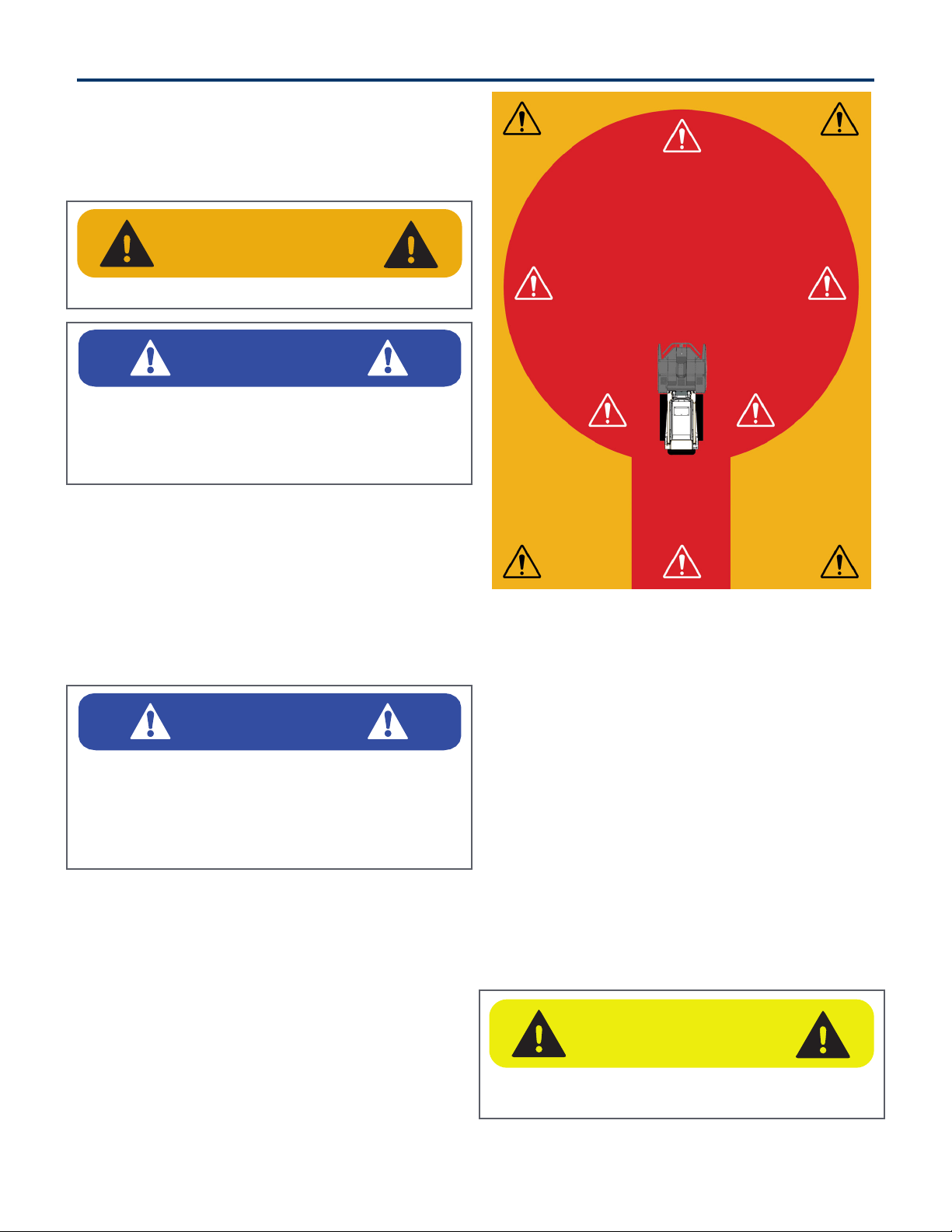
DANGER
STAY BACK 300 FEET
IMPORTANT
• DO NOT operate in a work area that has not
been cleared of foreign debris and obstacles.
• Rocks, metal, construction debris, and other
objects can damage the blade carrier and blades.
• Clearly mark any objects that cannot be removed.
CAUTION
DO NOT exceed 3000 continuous PSI operating
pressure. Serious damage can result.

15Blue Diamond® Attachments
3.4 Operating the Attachment
Cont’d
Initial Setup Cont’d
Stopping the Cutter
Position the mini skid steer brush cutter
approximately 6 inches (152 mm) o the ground.
Disengage the auxiliary hydraulic flow (see the
mini skid steer operator’s manual) to the cutter
head.
Cutting Procedures
Brush Cutting
Because hydraulic flow may be aected while
raising the cutter, it is best to work from top down.
Lift the cutter to the height needed to begin
cutting.
NOTE: Always keep the angle of the blades on a
plane or angle so blades are never visible from the
operator’s position.
Engage auxiliary hydraulics to begin blade rotation.
Slowly lower mini skid steer arms, bringing the
brush cutter straight down as possible.
Always keep the brush cutter tilted away from the
operator’s position by correcting the angle as you
drop.
Grass Cutting
Set the brush cutter on the ground and then raise
it up a few inches from the ground.
Engage auxiliary hydraulics to begin blade
rotation. Be careful to compensate for rising or
falling ground as you may need to raise or lower
brush cutter to compensate.
Tree Cutting
Keep the bottom of the brush cutter pointed away
from the cab, raise the brush cutter to the top of
tree / brush you intend to cut.
Engage auxiliary hydraulics to begin blade rotation.
Slowly lower mini skid steer arms, bringing the
brush cutter straight down as possible.
NOTE: Avoid positioning the center of the blade
carrier directly over the material being cut.
Position larger material toward the end of the
blades when lowering the brush cutter directly
down on trees or brush.
3. Operation
IMPORTANT
To minimize larger cut material discharging to the
rear, always keep the machine between material
being cut (work area) and buildings, occupied
areas, or roadways.
WARNING
Never allow blades to be visible from the
operator’s position, this means you are in the
direct line of discharge.

Blue Diamond® Attachments16
4. Maintenance
4.1 Service Schedule
DESCRIPTION
SERVICE PROCEDURES
Check Clean Lube Change Adjust Drain
Daily Maintenance (or every 8 hours)
Hydraulic Fittings •
Hydraulic Hoses •
Hydraulic Motor • •
Blades (wear, damage, and loosening) •
Blade Carrier •
All Hardware •
Deck • •
Weekly Maintenance (or every 40 hours)
Blade Bolt Torque - 500 ft/lb (678.0 N•m) •
All Hardware •
Deck (cracks, bends, or damage) •
Mount (cracks, bends, or damage) •
Monthly Maintenance
Blades (cracks, bends, or excessive wear) •
Skid plates •
All Hardware •
1000 Hour Maintenance
Drive Assembly •
17Blue Diamond® Attachments
4.2 Drive Assembly
Lubrication
Replace the oil in the direct drive assembly every
1000 hours.
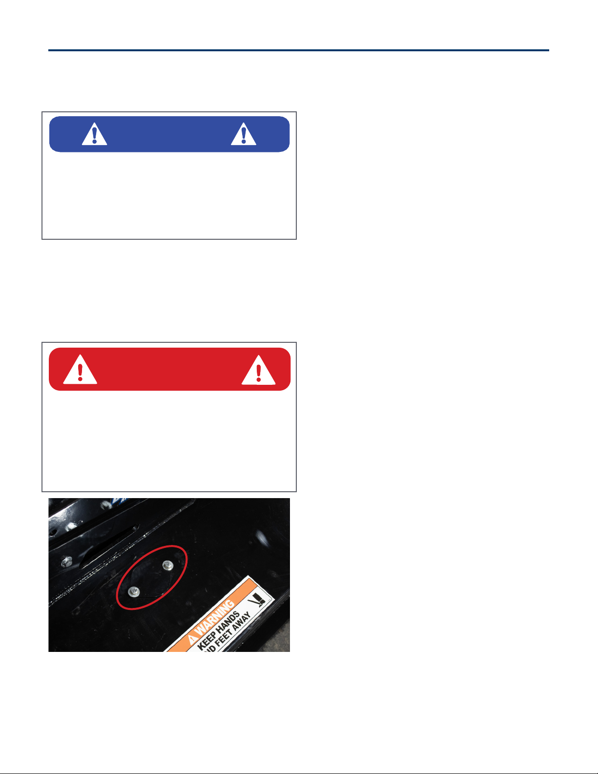
4.3 Blade Assembly
Blade Tightening / Replacement
Figure 2
Remove the two bolts (Item 1) [Figure 2] and cover
to access the blade nut.
Tightening Blade Bolts
Tighten bolts and nuts to 1440 ft/lb (1952 N•m) of
torque.
Turn blade carrier by hand to align the next blade
nut with the access hole.
Repeat procedure until all blade nuts and bolts
have been tightened.
Reinstall cover.
Blade Removal
Remove the nut and bolt from the blade. Remove
blade.
Turn blade carrier by hand to align the next blade
nut with the access hole.
Repeat procedure until all blade nuts and bolts
have been removed.
NOTE: Blue Diamond recommends replacing the
bolt and nut every time the blades are changed.
Blade Installation
Align blade with the hole in the blade carrier. Push
the bolt up through the blade into the blade carrier.
NOTE: Verify that blade bolt is fully seated.
Thread nut on blade bolt. Tighten nut to 1440 ft/lb
(1952 N•m) of torque.
Turn blade carrier to align remaining blade
mounting holes.
Repeat procedure until all blades have been
installed.
Reinstall cover.
4. Maintenance
IMPORTANT
Fluid such as hydraulic fluid, coolants, grease, etc.
must be disposed of in an environmentally safe
manner. Some regulations require that certain
spills and leaks on the ground must be cleaned
in a specific manner. See local, state, and federal
regulations for the correct disposal.
DANGER
AVOID SERIOUS INJURY OR DEATH
Before servicing the Brush Cutter:
• Lower and place the brush cutter on flat, level
surface.
• Engage parking brake, stop engine, and exit
the machine.
• Disconnect attachment hydraulic hoses.

Blue Diamond® Attachments18
4.4 Cleaning the Attachment
Park the machine and attachment on a flat level
surface. Lower the attachment flat on the ground.
Leave the operator’s position. See “Leaving the
Operator’s Position” on page 11.
Disconnect attachment hydraulic hoses from the
machine.
Enter the operator’s position. See “Entering the
Operator’s Position” on page 11.
Slowly raise the machine’s arms, while tilting the
brush cutter forward (down) until the front of the
brush cutter contacts the ground.
Stop the engine, engage the parking brake, and
leave the operator’s position. See “Leaving the
Operator’s Position” on page 11.
Use water or air pressure to clean debris from
under the brush cutter deck.
Be careful when removing any obstructions that
are wrapped around either the blades or the blade
carrier.
4. Maintenance
DANGER
AVOID SERIOUS INJURY OR DEATH
Before servicing the Brush Cutter:
• Raise the arms and tilt brush cutter fully forward
(down) until the front of the brush cutter
contacts the ground.
• Engage parking brake, stop engine, and exit
the machine.
• Disconnect attachment hydraulic hoses.

19Blue Diamond® Attachments
4. Maintenance
PROBLEM CAUSE SOLUTION
Cutter bogs down.
Dull blades. Remove and sharpen blades.
Ground speed too fast. Slow down ground speed.
Cutter speed too slow.
Raise engine RPMs or investigate other low oil
flow problems. Contact machine dealer or your
Blue Diamond Attachments® Product Support
Department.
Vibration felt when
running cutter.
Missing, loose, damaged, or
unbalanced cutter blades.
Replace blades with new or resharpened and
equally balanced blades.
Blade carrier damaged. Replace blade carrier.
Drive housing loose on
deck.
Tighten & torque drive mounting bolts. Replace
bolts if they are damaged.
Cutting height too low for
cutting in sandy or rocky
soils.
Raise cutter height.
Blades get dull too
quickly.
Blades have contacted solid
objects (rocks, steel pipes,
etc.)
Clear cutting area of solid objects before hitting
them, or raise the cutter height to clear exposed
rock surfaces.
Blades breaking. Excessive shock loads. Avoid hitting solid objects (rock, steel pipes, large
tree stumps, etc.)
Hydraulic oil level
goes down during
operation.
Leak at cutter motor or
other plumbing.
Investigate & repair. Contact your Blue Diamond
Attachments® Product Support Department.
Leak in machine hydraulic
system. Investigate & repair. Contact your machine dealer.
Blades do not spin
when auxiliary
hydraulics are
activated.
Hydraulic motor failed. Possible excessive hydraulic system pressure.
Contact your machine dealer.
Drive seized. Remove motor to isolate problems. Spin blade
carrier by hand to check drive.
4.5 Troubleshooting
Blue Diamond® Attachments20
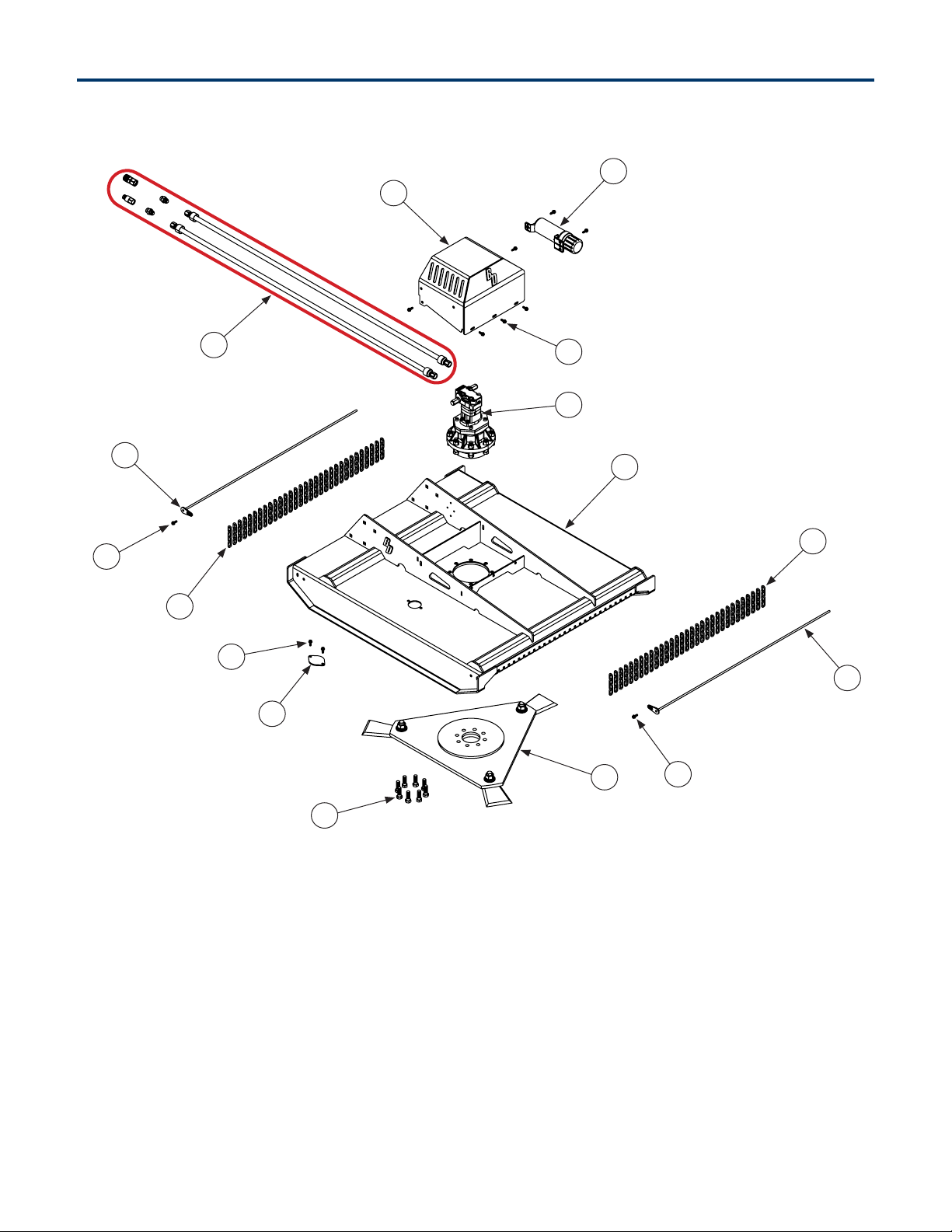
5. Parts
5.1 Parts Breakdown
3
2
8
4
6
9
8
10
8
7
11
58
9
10
1
Table of contents
Other Blue Diamond Brush Cutter manuals


