Blue Diamond 104605 User manual

Operation and Maintenance Manual
Swing Arm
Stump Grinder
888-376-7027 | BlueDiamondAttachments.com
Register your
WARRANTY
within 30 days
of purchase
104605, 104610, & 104615
Blue Diamond® Attachments2
Thank you for your decision to purchase a Blue Dia-
mond® Swing Arm Stump Grinder. To ensure maximum
performance of your equipment, it is mandatory that you
thoroughly study the Operator’s manual and follow the
recommendations. Proper operation and maintenance
are essential to maximize equipment life and prevent
personal injury.
Operate and maintain this equipment in a safe man-
ner and in accordance with all applicable local, state,
and federal codes, regulations and /or laws. Follow all
on-product labeling and instructions.
Make sure that all personnel have read this Operator’s
Manual and thoroughly understand safe and correct
operating, installation and maintenance procedures.
Blue Diamond is continually working to improve its
products. Blue Diamond reserves the right to make any
improvements or changes as deemed practical and pos-
sible without incurring any responsibility or obligation
to make any changes or additions to equipment sold
previously.
Although great care has been taken to ensure the
accuracy of this publication, Blue Diamond makes no
warranty or guarantee of any kind, written or expressed,
implied or otherwise with regard to the information
contained within this manual. Blue Diamond assumes
no responsibility for any errors that may appear in this
manual and shall not be liable under any circumstances
for incidental, consequential or punitive damages in con-
nection with, or arising from the use of this manual.
Keep this manual available for frequent reference. All
new operators or owners must review the manual before
using the equipment and annually thereafter. Contact
your Blue Diamond Attachments Dealer for assistance,
information, or additional copies of the manual. Contact
www.bluediamondattachments.com or call 888-376-
7027 for a complete list of dealers in your area.
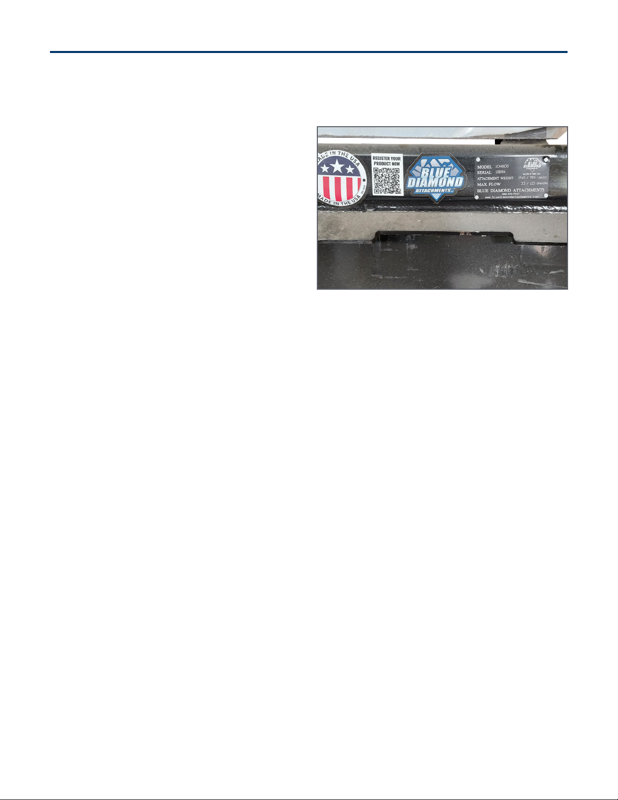
Serial Number Location:
Please record attachment information in the space pro-
vided for future reference.
Model Number:_____________________________
Serial Number: _____________________________
Dealer Name: ______________________________
Dealer Number:_____________________________
Date of Purchase:___________________________
The serial number plate is located on the mount frame
on the upper right hand side.
Always use your serial number when requesting infor-
mation or when ordering parts.
NOTE: The directions left, right, front and rear, as
mentioned throughout this manual, are as viewed from
the operator’s position.
Introduction: Owner Information
Revision Date: 06.14.2023

3Blue Diamond® Attachments
Table of Contents
1. Introduction......................................................................................4
1.1 About the Stump Grinder .........................................................4
2. Safety ...........................................................................................5-6
2.1 General Safety Information.................................................... 5
2.2 Operators.................................................................................. 6
3. Operation .................................................................................. 7-10
3.1 Entering and Exiting the Prime Mover..................................7
3.2 Attachment Installation...........................................................7
3.3 Pre-Operation Guidelines ..................................................... 8
3.4 How to Grind Stumps............................................................10
4. Maintenance ..................................................................................11
4.1 General Maintenance..............................................................11
5. Parts..........................................................................................12-22
5.1 Deck Assembly Front.............................................................12
5.2 Deck Assembly Back ............................................................15
5.3 Bolt Kit for Deck Assembly .................................................. 17
5.4 Manifold ...................................................................................19
5.5 Manifold Deck Assembly ....................................................20
5.6 Cutting Wheel.........................................................................21
5.7 Manual Tube...........................................................................22
6. Specifications .............................................................................. 23
6.1 Attachment Specifications ................................................... 23
6.2 SAE Torque Specifications.................................................. 24
6.3 Metric Torque Specifications..............................................25
7. Warranty ........................................................................................ 27

Blue Diamond® Attachments4
1.1 About the Grinder
The stump grinder attachment is intended for use in
stump grinding. Use of this attachment for any other
use is considered to be contrary to the intended use
of the attachment.
The Blue Diamond® Stump Grinder attachment is a
necessity for tree companies, landscapers, agricultural
producers, and rental companies looking to increase
their productivity and eciency when stump grinding.
The grinder is designed by people with years of
experience with attachments for machinery. You can
be sure that quality of our products is our first priority.
The grinder has been designed to deliver the
productivity of a dedicated machine with four to five
times less cost. This grinder is engineered for skid
steers with high flow hydraulics (29 – 45 GPM). A
hydraulic grinder motor for maximum productivity,
heavy weight for increased stability, and super high
eciency cutting performance are just a few features
that combine to bring you the world’s finest stump
grinder.
1. Introduction
5Blue Diamond® Attachments
2.1 General Safety Information Operating Safety
• Read and follow instructions in this manual and
the machine’s Operators Manual before operating.
• The manual must always remain with the machine.
In case of loss or damage, request a new copy
from your dealer or from Blue Diamond.
• Strictly follow all rules prescribed by the safety
pictograms/decals applied to the machine.
Ensure that all safety pictograms/decals are
legible. If pictograms/decals are worn, they
must be replaced with new ones obtained
from Blue Diamond and placed in the position
indicated by this manual.
• Before using the machine, make sure that
all safety devices are installed and in good
working conditions. In case of damage or
shields, replace them immediately.
• It is absolutely forbidden to remove or alter
safety devices and/or safety decals.
• Pay maximum attention to avoid any accidental
contact with rotating parts of the machine.
• If the use of the machine is required at night
or in conditions of reduced visibility, use
the lighting system of the prime mover and
possibly an auxiliary lighting system.
• Any modifications to the equipment may void
warranty and relieve Blue Diamond® of liability
of any resulting injury or damage.
2. Safety
CAUTION
The signal word CAUTION on the machine and
in the manuals indicates a potentially hazardous
situation which, if not avoided, may result in minor
or moderate injury. It may also be used to alert
against unsafe practices.
WARNING
The signal word WARNING on the machine and
in the manuals indicates a potentially hazardous
situation which, if not avoided, could result in
death or serious injury.
DANGER
The signal word DANGER on the machine and
in the manuals indicates a hazardous situation
which, if not avoided, will result in death or serious
injury.
SAFETY ALERT SYMBOL
This SAFETY ALERT SYMBOL identifies important
safety messages on the equipment and in the
owner’s manual. When you see this symbol, be
alert to the possibility of personal injury and
carefully read the message that follows.
IMPORTANT
The signal word IMPORTANT identifies
procedures which must be followed to avoid
damage to the machine.
WARNING
Leaking fluids under pressure can enter the skin
and cause serious injury or death. Immediate
medical attention is required.
Wear goggles. Use cardboard to check for leaks.
WARNING
Do not operate the grinder if any of the safety
guards are not in place.
Blue Diamond® Attachments6
2.2 Operators
Qualified Operators
The operator is a person suited to the work and
who is physically and psychologically able to
withstand the demands connected with operating
the equipment for its intended use. The operator
must not allow anyone to approach the machine
while it is working and must not allow external
personnel to operate the machine or attachment.
He is to follow the given instructions in this
manual and the machine operator’s manual in
order to obtain maximum performance, minimum
consumption, and maximum safety for himself and
for others.
The operator is responsible for scrupulously
observing all the instructions given in this manual.
Operator Training
• Check the rules and regulations at your
location. The rules may include an employer’s
work safety requirements. Regulations may
apply to local driving requirements or use
of a Slow Moving Vehicle (SMV) emblem.
Regulations may identify a hazard such as a
utility line.
• The new operator must start in an area without
bystanders and use all the controls until he or
she can operate the machine safely under all
conditions of the work area.
Operator Safety
• Before starting, and during operation of the
attachment, make sure there are no people
or animals in the operation area; the machine
can project material from the back with risks of
serious injury or death.
• During operation, adjustment, maintenance,
repairing, or transportation of the machine, the
operator must always use appropriate Personal
Protective Equipment (PPE) including but not
limited to safety glasses, working gloves, dust-
mask, safety helmet, and hearing protection.
• Do not operate the attachment or machine
while wearing loose fitting clothing that can be
entangled or caught in parts of the machine.
• Do not operate the implement when tired, not
in good condition, or under the influence of
alcohol or drugs.
2. Safety
AVOID SERIOUS INJURY OR DEATH
Operators must receive instructions before
operating the machine. Untrained operators can
cause serious injury or death.
For an operator to be qualified, he or she must
not use drugs or alcoholic drinks which impair
alertness or coordination while working. An
operator who is taking prescription drugs must
get medical advice to determine if he or she can
safely operate a machine and the equipment.
For an operator to be qualified, he or she must
have read and understood the instructions of
this manual, he or she must make adequate
preparation for the proper use of the machine,
and he or she must hold a driving license.
In case of doubt regarding the use of the machine
and/or the interpretation of this manual, the
operator must contact either their dealer or Blue
Diamond.
DANGER
Proper Workclothes: To help ensure your
safety as a designated operator wear
proper workclothes including tight fitting
clothes, protective gloves and shoes.
Safety Helmet and Eye/Ear Protection: To
help ensure your safety as a designated
operator wear a safety helmet and eye/
ear protection.

7Blue Diamond® Attachments
3.1 Entering and Exiting the
Prime Mover
Entering The Operator’s Position
Use the attachment safety treads, handles and
steps (on the machine) to enter the operator’s
position.
When in the operator’s position, lower safety seat
bar, start the engine and release the parking brake.
Leaving The Operator’s Position
Park the machine/attachment on a flat level
surface.
Place all controls in neutral, engage the park
brake, stop the engine and wait for all moving
parts to stop. Leave the operator’s position.
3.2 Attachment Installation
Connecting Attachment to the Prime
Mover
NOTE: Before attempting to attach the grinder to
the prime mover, verify that all hydraulic couplers
are compatible.
1. Place the grinder attachment on a level
surface.
2. Position and align the prime mover to the rear
of the attachment, within proximity of the front
of prime mover.
3. Insert and connect the prime mover into the
attachment.
4. Connect the hydraulic lines from the
attachment to the prime mover.
5. Close latches (or other locking mechanism) to
secure the attachment to the prime mover.
6. Using the prime mover with the Multifunction
controller and harness, raise the attachment
and move the attachment to ensure hydraulic
lines are clear of air and operate properly.
7. Lower the attachment to ground level.
3. Operation
WARNING
AVOID SERIOUS INJURY OR DEATH
• Always park on a flat level surface.
• Lower lift arms and place attachment flat on
the ground.
• Place all controls in NEUTRAL.
• Engage the park brake.
• Stop the engine and remove the key.
• Wait for all moving parts to stop.
SEE MACHINE’S OPERATOR’S MANUAL FOR
ADDITIONAL INFORMATION.
IMPORTANT
See the machine’s Operator’s Manual for detailed
information on operating the loader. CAUTION
Hydraulics should operate in an even and smooth
manner. Hydraulic movement that is not even and
smooth may indicate that air is in the hydraulic lines.
WARNING
Improper attachment to the prime mover may
cause personal injury.
CAUTION
All hydraulic connections must be clean and free
of debris before making any connections.
Blue Diamond® Attachments8
8. Route hoses away from pinch areas – install
cable ties if necessary to assure extended
hose life.
9. Inspect that the attachment is mounted
properly and securely. If the attachment
does not meet this requirement, follow the
instructions to remove the grinder and re-
attach using the instructions above.
Disconnecting Attachment from the
Prime Mover
1. Using the prime mover, lower the attachment
to the ground.
2. Relieve the pressure in the hydraulic system by
following these instructions:
a. Turn the ignition to o
b. Turn the ignition back to the on position
without starting the machine.
c. Move the auxiliary hydraulic function
level back and forth to relieve the pressure
in the hydraulic lines (this will greatly assist
you when hooking the unit back up so that
the hydraulic couplers connect easily).
3. Disconnect the hydraulic connection between
the attachment and the prime mover. To
prevent contamination, remove any dirt and
debris from the couplers.
4. Disengage the prime mover latches (or other
locking mechanism) from the attachment.
5. Remove the prime mover from the attachment.
NOTE: Hydraulic connections must be
disconnected before disengaging latches to
prevent damage to the prime mover or the
attachment.
3.3 Pre-Operation Guidelines
Equipment Inspection
NOTE: Replace any damaged hardware, hoses,
and fittings before using the equipment.
It is recommended to inspect the equipment for
damage and wear before use. Use the following
list as a guideline during equipment inspection.
It is recommended to inspect the equipment for
damage and wear before use. Use the following
list as a guideline during equipment inspection.
3. Operation
CAUTION
All hydraulic connections must be clean and free of
debris before disconnection.
WARNING
Improper disconnection may result in personal injury
or damage to the attachment and prime mover.
ITEMS
P
Check all hardware connections to the
prime mover for damage or fatigue such
as cracks or other structural flaws.
PCheck that all latches or locks are closed.
PCheck that all hydraulic fittings are tight
and free of leaks.
PCheck that all hydraulic lines are free of
leaks, holes, and/or cracks.
P
Check that the tires on the prime mover
are in good condition and have proper
load ratings.
WARNING
Leaking fluids under pressure can enter the skin
and cause serious injury or death. Immediate
medical attention is required.
Keep body parts away from the leaking hydraulic
lines and couplers that are under pressure.
Wear goggles. Never use hands to check for
hydraulic leaks. Use cardboard to check for leaks.
9Blue Diamond® Attachments
3.3 Pre-Operation Guidelines
Cont’d
Usage Guidelines
Before each use of the stump grinder, do the
following:
• Perform the equipment inspection by
performing a walk around.
• Perform daily inspection as indicated on the
Inspection Checklist on page 8.
• Verify that the proper attachment is being used
for the task.
• As with any power attachment, safety is
critical. An enclosed cab prime mover with
the operation wearing safety protection is
required.
• Never operate the grinder with persons within
100 feet of range.
• Disengage grinder and shut o the engine
before leaving the cabin of the prime mover.
• Use caution on slopes and uneven terrain.
• Never carry passengers.
• Never leave the machine running unattended.
• Never leave the stump grinder o the ground
when out of the operator’s seat.
• Never allow children or untrained personnel to
operate the grinder.
Inspection Checklist
3. Operation
CAUTION
Always be aware of what is overhead when
operating the grinder.
DANGER
Keep all body parts away from the grinder when
in use. The pivoting blade is dangerous and
hazardous and could potentially cause serious
bodily injury or death.
ITEMS
PAre all safety notices and warning
stickers in proper locations and visible?
PAre there any visible hydraulic leaks?
PAre any cracks visible in structure of the
grinder?
PIs the cutting wheel bent?
PAre bolts holding teeth secure and tight?
P
Has the prime mover been properly
inspected for hydraulic leaks and proper
tire inflation?
PHas the prime mover been properly
maintained?
Blue Diamond® Attachments10
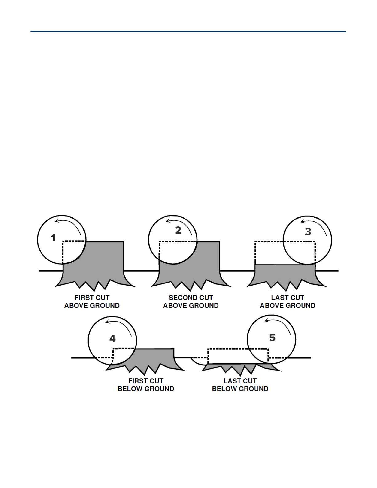
3.4 How to Grind Stumps
Align the cutter wheel with the left side of the
stump (viewed from the machine control area) and
position the machine so that it will cut about 4-6
inches o the top of the stump and 8-12 inches
from the left side of the stump [Figure 1].
The rate of cut will depend on the type of tree,
condition of the wood, and the condition of the
cutters. Too light a feed will produce sawdust.
The ideal feeding rate produces heavy wood
chips, some of which may be about 1/16” thick by
approximately 6-8 inches long, as well as chunks
of wood. After completing the first cut through
the stump, move the machine to the right (again
as viewed from the control area) so the wheel can
cut another 8-12 inches. Proceed with another cut.
Additional passes, when the tree stump is very
large, are made in the same manner as described
above. Repeat the procedure until the stump is cut
to ground level.
Before cutting below the ground level, make
certain that all rock or stone is removed from the
immediate area of the cutting wheel. When you
are cutting below the ground level, the feed rate
should be reduced and the operator should be
alert to the possibility of cutting hidden rock. Extra
care used in this part of the operation can avoid
costly damage to the cutting wheel and teeth.
The wheel is designed so that it can “saw” or cut
its way into solid wood by dropping straight down
on it. This operation works well for cutting o
large roots.
3. Operation
Figure 1

11Blue Diamond® Attachments
4.1 General Maintenance
NOTE: Disconnect the hydraulic connection
between the attachment and the prime mover
before performing any type of maintenance on the
grinder.
Cutting Wheel
Be certain to check carbide cutting teeth for wear.
Replace teeth as necessary.
Hoses
Check hoses occasionally for abrasion damage.
This may save you from downtime. If in doubt,
replace with genuine Blue Diamond® parts.
Pivot Pins
Pivot pins may be lubed with moly-type grease,
same as what is used on your machine. Please
check the cotter pins that retain all pivot/anchor
pins after each use. If missing, replace! Severe
damage could be caused by losing a pin.
Storage
Lubrication of pivot pins is recommended if unit
is stored outside. Be certain hydraulic quick
couplers are cleaned and joined together to keep
dirt out. A light coating of oil film or diesel fluid
is recommended to prevent corrosion. Touch-up
paint should be used on all scratches to prevent
further rust.
Grease Points
There are 7 grease points on the grinder. Each
grease point should have new grease applied daily
when being used. Approximately every 8 hrs. See
Figures 2, 3, and 4 for grease point locations.
Figure 2
Figure 3
Figure 4
4. Maintenance
Blue Diamond® Attachments12
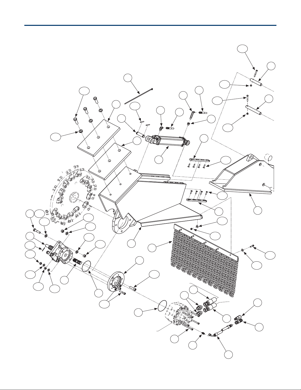
5. Parts
5.1 Deck Assembly Front
3.16
36
3.16
3.7
3.7
35
22
15
16
6
3.18
9
24
13
34
45
45
3.10
3.2
3.18
644
3.4
3.7
3.4
3.14
46
47
48
3.11
3.12
11
2
17
29
18
19
30
31
20
11
3.1733
3.1
10
3.13
3.3
3.8
3.8 3.3
40
Piston Motor Assembly
Pressure
Return
3.9
32
3.6
3.1
3.1
3.6

13Blue Diamond® Attachments
5. Parts
ITEM PART NUMBER DESCRIPTION QTY TORQUE
(ft-lb)
Piston
Motor
204093 Motor, 60cc, 16-20 GPM, High Press Seal
1
204077 Motor, 75cc, 21-24 GPM, High Press Seal
204075 Motor, 90cc, 25-28 GPM, High Press Seal
204204 Motor, 130cc, 29-33 GPM, High Press Seal
204097 Motor, 150cc, 34-39 GPM, High Press Seal
204095 Motor, 170cc, 40-45 GPM, High Press Seal
NS 204085 Motor Shaft Seal 1
2 203415 M10-1.5 X 120mm Socket Cap Screw, Gr 12.0 5 62
3 204484 Bolt Kit 1
3.1 299844 5/8 X 1.312 Thru-Hardened SAE FW, Yellow Zinc 10
3.2 299727 3/4 SAE Gr 8 Flat Washer, Yellow 3
3.3 299732 1/2 SAE Flat Washer Gr 8, Yellow Zinc 2
3.4 299725 3/8 Thru-Hardened Flat Washer, Yellow Zinc 22
3.6 109177 5/8"-11 Grade C Steel Top Lock 6 64
3.7 299625 3/8" NC Nylock Nut, Gr 8 15
3.8 204302 1/2-13 Top Lock Nut Gr C, Zinc 2 106
3.9 204482 Roll Pin, 1/4' X 2" 2
3.10 299489 3/4-10 X 2-3/4 Gr 8 Hex Cap Screw, Yellow Zinc 3 376
3.11 299453 5/8"-11 X 2-1/4" Socket Cap Screw, Plain 2 *238
3.12 299325 1/2-13 X 2-1/4 ASTM A574 Socket Cap, Black Oxide 2 *124
3.13 204061 M5 X 4mm Spring Pin, Plain 1
3.14 299487 3/8"-16 X 1-1/2" Gr 8 Hex Cap, Yellow Zinc 9 44
3.16 299329 3/8"-16 X 2-1/2" Gr 8 Hex Cap, Yellow Zinc 2 44
3.17 299459 5/8"-11 X 2-3/4" Gr 8 Hex Cap, Yellow Zinc 4 *212
3.18 299311 5/16”-18 X 1-1/4” Flat Socket Cap Screw, Black 16 29
5 204475 Cylinder - Tie Rod 2.50 X 12.0 1
6 204485 Block Slide, UHMW, Floating 4
8 (NS) 204455 Harness, 6-Function, Attachment Side 1
9 (NS) 204452 Controller, Multi-Function, Handheld 1
10 204220 Bearing Housing - DMG/DSG 1
5.1 Deck Assembly Cont’d
*Critical Torque Values MUST be followed.

Blue Diamond® Attachments14
ITEM PART NUMBER DESCRIPTION QTY TORQUE
(ft-lb)
11 204207 O-Ring, Stump Grinder 2
13 295030-M04JIC-M06NPT 1/4" MJIC X 3/8" MP–90EG, Fitting 2
15 295030-M04JIC-M04NPTXL 1/4" MJIC X 1/4" MP–90DEG, Fitting X-Long 1
16 204488 3/8" MP X 1/4" FP, Bushing 1
17 204416 6 MJIC X 4 BSPP Adapter 1
18 224064 3/8" Male Quick Coupler, Flat Face, No Spill 1
19 224063 3/8" Female Quick Coupler, Flat Face, No Spill 1
20 295010-M16ORFS-M16ORB –16 MOR X –16 MOFS 2
22 204489 Hose 1/4" X 21" (1/4" FJIC X 1/4" FJIC) 2
24 204491 Hose 1/4" X 36" (1/4" FJIC X 1/4" FJIC) 1
29 204496 Hose 3/8" X 143" (3/8" FJIC – 90 DEG X 1/2" MP) 1
30 204497 Motor to Manifold Pressure Hose 1 X 67” 4000 PSI (-16 FFS X -16FFS) Kevlar 2
31 204498 Motor to Manifold Return Hose 1” X 67 3000 PSI (1”FJIC X - 16FFS) Kevlar 2
32 204081 14" Zip Tie, Wide 4
33 204063 Loctite 243, 0.5mL (Blue) 1
34 204465 Clevis Pin, 1" X 3-1/2" 1
35 204500 Pin, Lift, Base End 1
36 204501 Pin, Lift, Rod End 1
40 204067 Stub Shaft, A3 Spline, For High Press HC05 Motor 1
44 204445 Beam 1
45 204446 Counter Weight Plate 2
46 204447 Bracket-Chain 1
47 204448 Slider 1
48 204069 Adapter - Motor 1
5. Parts
5.1 Deck Assembly Front Cont’d

15Blue Diamond® Attachments
5. Parts
5.2 Deck Assembly Back
41 3.14
3.4
3.15
3.7
43.1
38
43
26
14
21
4.1
43.2
42
7
27
14
21
39
3.15
44.1
42.1
3.7
37
49
1
3.5
44.1
3.4
43.2
4.1 4.2
3.4 3.7
4.1
3.4
3.7
28
12
4
25
12 22
13
4
23
12
31
30
Return
Pressure
Return
Pressure Manifold

Blue Diamond® Attachments16
ITEM PART NUMBER DESCRIPTION QTY TORQUE
ft-lb
1 204483 Snap Ring, 1” External 2
3 204484 Bolt Kit 1
3.4 299725 3/8 Thru-Hardened Flat Washer, Yellow Zinc 22
3.5 299486 3/8-16 X 5 Gr 5 Hex Cap, Zinc 2 31
3.7 299625 3/8" NC Nylock Nut, Gr 8 15
3.14 299487 3/8" -16 X 1-1/2" Gr 8 Hex Cap, Yellow Zinc 9 44
3.15 299488 3/8"-16 X 3-3/4" Gr 8 Hex Cap, Yellow Zinc 2 44
4 204476 Cylinder - Tie Rod 2.50 X 6.00 2
4.1 204481 3/16 R-Clip 4
4.2 204465 Clevis Pin, 1' X 3-1/2" 2
7 204486 Cylinder - Welded 3/50 X 8.00 1
12 295010-M04JIC-M06NPT 1/4" MJIC X 3/8" MP, Fitting 3
13 295030-M04JIC-M06NPT 1/4" MJIC X 3/8" MP-90deg, Fitting 2
14 295030-M04JIC-F04JIC 1/4" MJIC X 1/4" FJIC-90deg, Fitting 2
21 295010-M04JIC-M08NPT 1/4" MJIC X 1/2" MP, Fitting 2
22 204490 Hose 1/4" X 21" (1/4"FJIC X 1/4" FJIC) 2
23 204490 Hose 1/4" X 28" (1/4"FJIC X 1/4" FJIC) 1
25 204492 Hose 1/4" X 26" (1/4"FJIC X 1/4" FJIC-90deg) 1
26 204493 Hose 1/4" X 21" (1/4"FJIC X 1/4" FJIC-45deg) 1
27 204494 Hose 1/4" X 25" (1/4"FJIC X 1/4" FJIC-45deg) 1
28 204495 Hose 1/4" X 30" (1/4"FJIC X 1/4" FJIC) 1
30 204497 Motor to Manifold Pressure Hose 1 X 67” 4000 PSI (–16 FFS X –16FFS) Kevlar 2
31 204498 Motor to Manifold Return Hose 1” X 67 3000 PSI (1”FJIC X - 16FFS) Kevlar 2
37 204502 Pin, Telescopic Base 1
38 204503 Pin, Center Rotation 1
39 204504 Pin, Center Tilt 1
41 204602 Safety Glass 1
42 204480 Swivel 1
42.1 203072 Grease Zerk 1/4" Straight 2
43 204700 Skid Attach Brkt 1
43.1 204478 Bushing-Garlock 2.25 X 2 X 2 2
43.2 203072 Grease Zerk 1/4" Straight 2
44.1 204478 Bushing-Garlock 2.25 X 2 X 2 2
49 204449 Washer, Machined 2
5. Parts
5.2 Deck Assembly Back Cont’d

17Blue Diamond® Attachments
5. Parts
5.3 Bolt Kit for Deck Assembly
1019
2
13 6
1
8
3
11
12
1720
4
7
4
14
9
18
7
16
21 7
15
16
4
5
21
7
4
21
4
7
21
7
15
14 4

Blue Diamond® Attachments18
ITEM PART NUMBER DESCRIPTION QTY TORQUE
ft-lb
TORQUE
Nm
— 204484 Bolt Kit 1
1 299844 5/8 X 1.312 Thru-Hardened SAE Flat Washer, Yellow Zinc 10
2 299727 3/4 SAE Gr 8 Flat Washer, Yellow 3
3 299732 1/2 X 1.062 Gr 8 SAE Flat Washer, Yellow Zinc 2
4 299725 3/8 Thru-Hardened Flat Washer, Yellow Zinc 22
5 299486 3/8-16 X 5 Gr 5 Hex Cap, Zinc 2 31 42
6 109177 5/8"-11 Grade C Steel Top Lock 6
7 299625 3/8" NC Nylock Nut, Gr 8 15
8 204302 1/2-13 Top Lock Nut Gr C, Zinc 2
9 204482 Roll Pin, 1/4' X 2 2
10 299489 3/4-10 X 2-3/4 Gr 8 Hex Cap Screw, Yellow Zinc 3 376 510
11 299453 5/8-11 X 2-1/4 ASTM A574 Socket Cap, Black Oxide 2 238 323
12 299325 1/2-13 X 2-1/4 ASTM A574 Socket Cap, Black Oxide 2 124 168
13 299453 M5 X 40mm Spring Pin, Plain 1
14 299325 38"-16 X 1-1/2" Gr 8 Hex Cap, Yellow Zinc 9 44 60
15 204061 38"-16 X 3-3/4" Gr 8 Hex Cap, Yellow Zinc 2 44 60
16 299487 38"-16 X 2-3/4" Gr 8 Hex Cap, Yellow Zinc 2 44 60
17 299488 5/8-11 X 2-3/4 Gr 8 Hex Cap, Yellow Zinc 4 212 287
18 299329 5/16"-18 X 1-1/4" Flat Socket Cap Screw, Black 16 29 39
19 204082 Loctite Red 262 1
20 204063 Loctite Blue 243 1
21 204478 Bushing Garlock 2.25 X 2 X 2 4
5. Parts

19Blue Diamond® Attachments
5. Parts
5.4 Manifold
ITEM PART NUMBER DESCRIPTION QTY
1 204437 Spool-Type 4-Way 3-Position Tandem Center Valve 2
2 204438 Relief Dierential Area Poppet-Type Relief Valve 1
3 204439 Relief Direct-Acting Poppet-Type Relief Valve 1
4 204440 Piloted Spool-Type Logic Element 1
5 204441 Pilot-Operated Check Valve 1
6 204442 Check Valve 1
7 204443 Coil Spacer 3
8 204487 Solenoid Valve Coil 6
9 204444 Spool-Type 4-Way 3-Position Open Center Valve 1
8
7
8
1
9
1
5
6
2
4
3

Blue Diamond® Attachments20
5. Parts
5.5 Manifold Deck Assembly
ITEM PART NUMBER DESCRIPTION QTY
1 295010-M16ORB-M16JIC 1 MOR X 1 MJIC, Adapter 2
2 295010-M04JIC-M06ORB 1/4" MJIC X 3/8" MORB, Fitting 5
3 295050-M04JIC-M04JIC-M06ORB 1/4" MJ X 1/4" MJ X 3/8" MORB, Tee 1
4 295050-M04JIC-F04JIC-M04JIC 1/4" MJ X 1/4" FJ X 1/4" MJ, Tee 1
5 295030-M04JIC-F04JIC 1/4" MJIC X 1/4" FJIC-90deg, Fitting 1
6 224012 1/2" Male Quick Coupler X 3/4" SAE, Flat Face, No Spill 1
7 224011 1/2" Female Quick Coupler X 3/4" SAE, Flat Face, No Spill 1
8 295010-M16ORFS-M16ORB -16 MOR X -16 MOFS 2
9 290320 Adapter, -16 MFS X -12 MOR 2
10 204489 Hose 1/4" X 21" (1/4" FJIC X 1/4” FJIC) 2
11 204490 Hose 1/4" X 28" (1/4" FJIC X 1/4” FJIC) 1
12 204491 Hose 1/4" X 36" (1/4" FJIC X 1/4” FJIC) 1
13 204492 Hose 1/4" X 26" (1/4" FJIC X 1/4” FJIC-90deg) 1
14 204493 Hose 1/4" X 21" (1/4" FJIC X 1/4” FJIC-90deg) 1
15 204494 Hose 1/4" X 25" (1/4" FJIC X 1/4” FJIC-45deg) 1
16 204495 Hose 1/4" X 30" (1/4" FJIC X 1/4” FJIC) 1
17 204497 Motor to Manifold Pressure Hose 1 X 67” 4000 PSI (–16 FFS X –16FFS) Kevlar 2
18 204498 Hose 1" X 67 3000 Psi (1" Fjic X -16s) Kevlar 2
19 204436 Manifold, Valve Assemply 1
19
14
15
2
13
11 4
10
3
1
1
2
7
6
9
9
17
18
1
8
10
2
7 8
19
12
18
17
This manual suits for next models
2
Table of contents
Other Blue Diamond Grinder manuals


