Makita DGA700 User manual

INSTRUCTION MANUAL
Cordless Angle Grinder
DGA700
DGA900
ENGLISH: Original instructions
Read before use.

2ENGLISH
SPECIFICATIONS
Model: DGA700 DGA900
Wheel diameter 180mm 230mm
Max. wheel thickness 7.2mm 6.5mm
Spindle thread
7,800min-1 6,000min-1
Overall length 499mm
Rated voltage D.C.36 V
BL1815N, BL1820, BL1820B, BL1830, BL1830B, BL1840,
BL1840B, BL1850, BL1850B, BL1860B
Net weight 5.0 - 6.0 kg 5.2 - 8.0 kg
without notice.
-
Symbols
-
use.
Read instruction manual.
Ni-MH
Li-ion
pack together with household waste material!
In observance of the European Directives,
-
mentation in accordance with national laws,
Intended use
metal and stone materials without the use of water.
Noise
-
ing to EN60745:
Model DGA700
Model DGA900
WARNING: Wear ear protection.
Vibration
-
mined according to EN60745:
Model DGA700
Work mode: surface grinding with normal side grip
2
2
Work mode: surface grinding with anti vibration side grip
2
2
Work mode: disc sanding with normal side grip
h, DS2or less
2
Work mode: disc sanding with anti vibration side grip
h, DS2or less
2
Model DGA900
Work mode: surface grinding with normal side grip
2
2
Work mode: surface grinding with anti vibration side grip
2
2
Work mode: disc sanding with normal side grip
h, DS2or less
2
Work mode: disc sanding with anti vibration side grip
h, DS2or less
2
NOTE:
been measured in accordance with the standard test
another.
NOTE:
exposure.

3ENGLISH
WARNING:
use of the power tool can differ from the declared
tool is used.
WARNING:
to protect the operator that are based on an estima-
the times when the tool is switched off and when it is
WARNING:
value is used for main applications of the power tool.
However if the power tool is used for other applica-
EC Declaration of Conformity
For European countries only
to this instruction manual.
SAFETY WARNINGS
General power tool safety warnings
WARNING: Read all safety warnings, instruc-
with this power tool. Failure to follow all instructions
-
tions for future reference.
Work area safety
1. Keep work area clean and well lit. Cluttered or
dark areas invite accidents.
2. -
liquids, gases or dust. Power tools create sparks
3. Keep children and bystanders away while
operating a power tool. Distractions can cause
Electrical Safety
1.
modify the plug in any way. Do not use any
adapter plugs with earthed (grounded) power
tools.
reduce risk of electric shock.
2.
surfaces, such as pipes, radiators, ranges and
refrigerators.-
3. Do not expose power tools to rain or wet con-
ditions. Water entering a power tool will increase
the risk of electric shock.
4.
carrying, pulling or unplugging the power tool.
Keep cord away from heat, oil, sharp edges
Damaged or entangled cords
increase the risk of electric shock.
5. When operating a power tool outdoors, use an
extension cord suitable for outdoor use.
a cord suitable for outdoor use reduces the risk of
electric shock.
6. If operating a power tool in a damp location
(RCD) protected supply.
the risk of electric shock.
7. Power tools can produce electromagnetic
However, users of pacemakers and other similar
medical devices should contact the maker of their
device and/or doctor for advice before operating
this power tool.
Personal Safety
1. Stay alert, watch what you are doing and use
common sense when operating a power tool.
Do not use a power tool while you are tired or
-
ication.
2.
wear eye protection.
hearing protection used for appropriate conditions
3.
switch is in the off-position before connecting
to power source and/or battery pack, picking
up or carrying the tool.
that have the switch on invites accidents.
4.
turning the power tool on.
5.
balance at all times.
of the power tool in unexpected situations.
6. Dress properly. Do not wear loose clothing or
long hair can be caught in moving parts.
7.
dust extraction and collection facilities, ensure
these are connected and properly used.
dust collection can reduce dust-related hazards.
8. Do not let familiarity gained from frequent use
of tools allow you to become complacent and
ignore tool safety principles.
second.
9.
The goggles must comply with ANSI Z87.1 in
the USA, EN 166 in Europe, or AS/NZS 1336
in Australia/New Zealand. In Australia/New
Zealand, it is legally required to wear a face
shield to protect your face, too.

4ENGLISH
It is an employer's responsibility to enforce
-
ments by the tool operators and by other per-
sons in the immediate working area.
Power tool use and care
1. Do not force the power tool. Use the correct
power tool for your application.
rate for which it was designed.
2.
Do not use the power tool if the switch does not turn
it on and off.
with the switch is dangerous and must be repaired.
3. Disconnect the plug from the power source
-
ments, changing accessories, or storing power
tools.
4. Store idle power tools out of the reach of chil-
dren and do not allow persons unfamiliar with
the power tool or these instructions to operate
the power tool. Power tools are dangerous in the
hands of untrained users.
5.
Maintain power tools and accessories. Check for
-
age of parts and any other condition that may
the power tool repaired before use.
6. Keep cutting tools sharp and clean.
maintained cutting tools with sharp cutting edges
7.
Use the power tool, accessories and tool bits etc.
in accordance with these instructions, taking into
account the working conditions and the work to be
performed.
from those intended could result in a hazardous situation.
8.
Keep handles and grasping surfaces dry, clean
and free from oil and grease.
grasping surfaces do not allow for safe handling and
control of the tool in unexpected situations.
9. When using the tool, do not wear cloth work
-
Battery tool use and care
1.
the manufacturer.
2. -
nated battery packs.
3. When battery pack is not in use, keep it away
coins, keys, nails, screws or other small metal
terminal to another.-
4.
-
-
tacts eyes, additionally seek medical help.
5. Do not use a battery pack or tool that is dam-
6.
-
7. Follow all charging instructions and do not
charge the battery pack or tool outside the
-
tions.
1.
repair person using only identical replacement
parts.
tool is maintained.
2. Service
manufacturer or authorized service providers.
3. Follow instruction for lubricating and chang-
ing accessories.
Cordless grinder safety warnings
Safety Warnings Common for Grinding, Sanding,
1.
This power tool is intended to function as a
grinder, sander, wire brush or cut-off tool. Read
all safety warnings, instructions, illustrations
2.
Operations such as polishing are not recom-
mended to be performed with this power tool.
Operations for which the power tool was not designed
3. -
cally designed and recommended by the tool
manufacturer.
safe operation.
4. The rated speed of the accessory must be at
least equal to the maximum speed marked on
the power tool.
5. The outside diameter and the thickness of your
accessory must be within the capacity rating
of your power tool.

5ENGLISH
6.
Threaded mounting of accessories must match
the grinder spindle thread. For accessories
hardware of the power tool will run out of balance,
7.
Do not use a damaged accessory. Before each
wheels for chips and cracks, backing pad for
cracks, tear or excess wear, wire brush for loose
or cracked wires. If power tool or accessory
is dropped, inspect for damage or install an
undamaged accessory. After inspecting and
installing an accessory, position yourself and
bystanders away from the plane of the rotating
accessory and run the power tool at maximum
no-load speed for one minute. Damaged acces-
8.
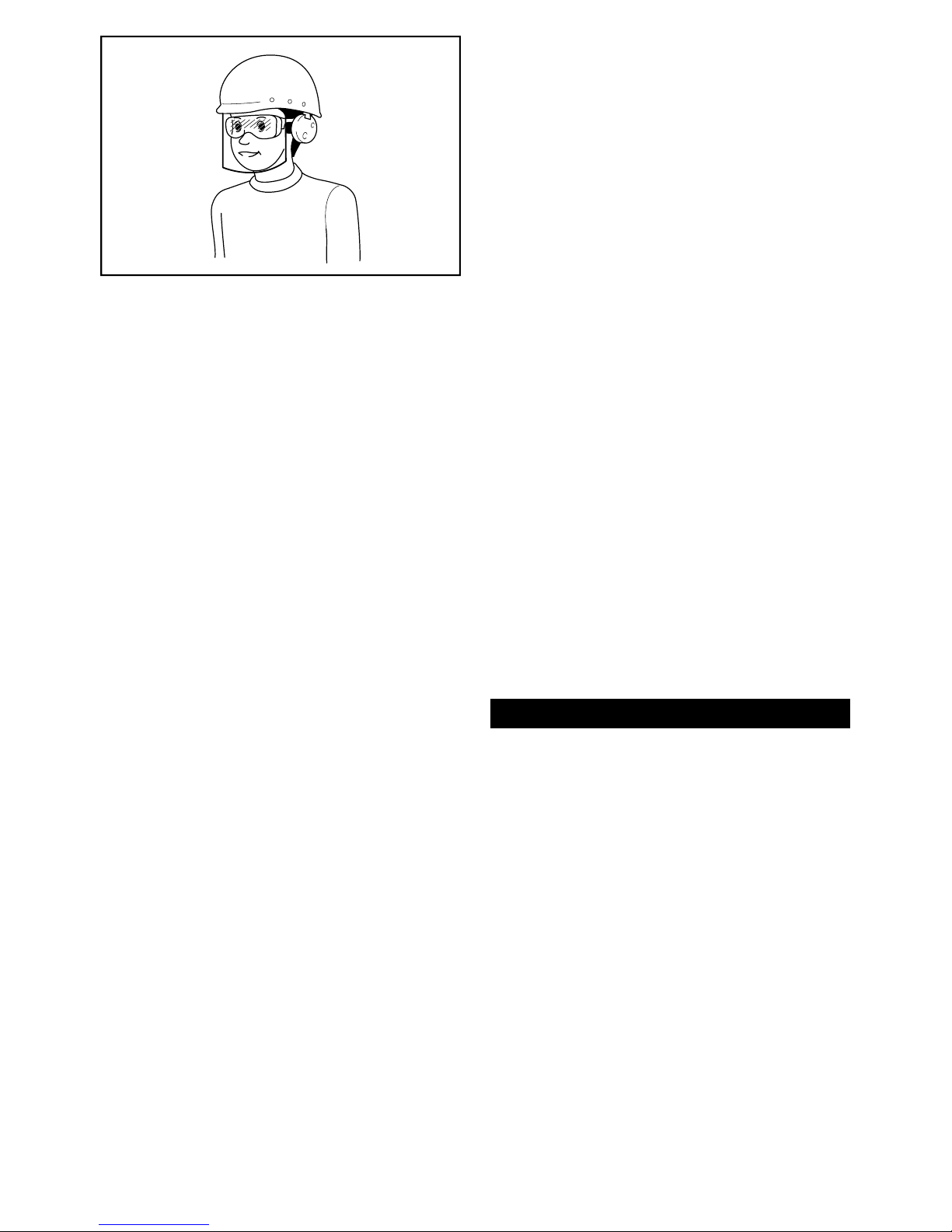
Depending on application, use face shield,
safety goggles or safety glasses. As appropri-
and workshop apron capable of stopping small
-
9.
Keep bystanders a safe distance away from work
area. Anyone entering the work area must wear
Fragments of
10. Hold the power tool by insulated gripping
surfaces only, when performing an operation
where the cutting tool may contact hidden
wiring.
could give the operator an electric shock.
11. -
sory has come to a complete stop.
12. Do not run the power tool while carrying it at
your side.
13.
motor’s fan will draw the dust inside the housing
and excessive accumulation of powdered metal
14.
materials. Sparks could ignite these materials.
15. Do not use accessories that require liquid
coolants.
Kickback and Related Warnings
-
-
trolled power tool to be forced in the direction opposite
For example, if an abrasive wheel is snagged or
entering into the pinch point can dig into the surface of
the material causing the wheel to climb out or kick out.
operator, depending on direction of the wheel’s move-
break under these conditions.
incorrect operating procedures or conditions and can be
1.
position your body and arm to allow you to
resist kickback forces. Always use auxiliary
kickback or torque reaction during start-up.
-
back forces, if proper precautions are taken.
2. -
sory.
3. Do not position your body in the area where
to the wheel’s movement at the point of snagging.
4. Use special care when working corners, sharp
accessory. Corners, sharp edges or bouncing
and cause loss of control or kickback.
5.
or toothed saw blade. Such blades create fre-
Cutting-Off Operations:
1. Use only wheel types that are recommended
designed for the selected wheel. Wheels for
which the power tool was not designed cannot be
2. The grinding surface of centre depressed
wheels must be mounted below the plane of
the guard lip.
3.
The guard must be securely attached to the
power tool and positioned for maximum safety,
so the least amount of wheel is exposed towards
the operator. -
tor from broken wheel fragments, accidental contact
with wheel and sparks that could ignite clothing.
4.
Wheels must be used only for recommended
applications. For example: do not grind with the
side of cut-off wheel.
intended for peripheral grinding, side forces applied
5.
of correct size and shape for your selected
wheel.
6. Do not use worn down wheels from larger
power tools. Wheel intended for larger power tool
is not suitable for the higher speed of a smaller

6ENGLISH
Cutting-Off Operations:
1. -
Overstressing the wheel
or binding of the wheel in the cut and the possibil-
2. Do not position your body in line with and
behind the rotating wheel. When the wheel, at
-
3. When wheel is binding or when interrupting
a cut for any reason, switch off the power
tool and hold the power tool motionless until
cut while the wheel is in motion otherwise
kickback may occur. Investigate and take correc-
tive action to eliminate the cause of wheel binding.
4.
Do not restart the cutting operation in the work-
piece. Let the wheel reach full speed and carefully
re-enter the cut.
kickback if the power tool is restarted in the workpiece.
5.
minimize the risk of wheel pinching and kick-
back. Large workpieces tend to sag under their
own weight. Supports must be placed under the
workpiece near the line of cut and near the edge
of the workpiece on both sides of the wheel.
6. Use extra caution when making a “pocket cut”
into existing walls or other blind areas.
-
1.
disc paper. Follow manufacturers recommen-
dations, when selecting sanding paper. Larger
snagging, tearing of the disc or kickback.
1. Be aware that wire bristles are thrown by the
load to the brush.
penetrate light clothing and/or skin.
2. If the use of a guard is recommended for wire
brushing, do not allow any interference of the
wire wheel or brush with the guard. Wire wheel
and centrifugal forces.
Additional Safety Warnings:
1.
When using depressed centre grinding wheels,
2. NEVER USE Stone Cup type wheels with this
grinder.
3. Be careful not to damage the spindle, the
lock nut. Damage to these parts could result in
wheel breakage.
4. Make sure the wheel is not contacting the
workpiece before the switch is turned on.
5. Before using the tool on an actual workpiece,
wobbling that could indicate poor installation
or a poorly balanced wheel.
6. -
form the grinding.
7.
only when hand-held.
8. Do not touch the workpiece immediately after
operation; it may be extremely hot and could
burn your skin.
9.
for correct mounting and use of wheels.
Handle and store wheels with care.
10. Do not use separate reducing bushings or
11.
12.
hole wheel, ensure that the thread in the wheel
is long enough to accept the spindle length.
13. Check that the workpiece is properly
supported.
14. Pay attention that the wheel continues to
rotate after the tool is switched off.
15. If working place is extremely hot and humid,
short-circuit breaker (30 mA) to assure opera-
tor safety.
16. Do not use the tool on any materials contain-
ing asbestos.
17. When use cut-off wheel, always work with
the dust collecting wheel guard required by
domestic regulation.
18.
lateral pressure.
19.
causes tool breakage.
SAVE THESE INSTRUCTIONS.
WARNING: DO NOT let comfort or familiarity
with product (gained from repeated use) replace
product. MISUSE or failure to follow the safety
rules stated in this instruction manual may cause
Important safety instructions for
battery cartridge
1. Before using battery cartridge, read all instruc-
tions and cautionary markings on (1) battery
charger, (2) battery, and (3) product using
battery.
2. Do not disassemble battery cartridge.
3.
shorter, stop operating immediately. It may

7ENGLISH
4. If electrolyte gets into your eyes, rinse them
out with clear water and seek medical atten-
tion right away. It may result in loss of your
eyesight.
5. Do not short the battery cartridge:
Do not touch the terminals with any con-
-
nails, coins, etc.
Do not expose battery cartridge to water
or rain.
A battery short can cause a large current
breakdown.
6. Do not store the tool and battery cartridge in
locations where the temperature may reach or
exceed 50 °C (122 °F).
7.
8. Be careful not to drop or strike battery.
9. Do not use a damaged battery.
10.
to the Dangerous Goods Legislation require-
ments.
-
aging and labeling must be observed.
For preparation of the item being shipped, consult-
national regulations.
around in the packaging.
11. Follow your local regulations relating to dis-
posal of battery.
SAVE THESE INSTRUCTIONS.
CAUTION: Only use genuine Makita batteries.
charger.
Tips for maintaining maximum
battery life
1. Charge the battery cartridge before completely
discharged. Always stop tool operation and
charge the battery cartridge when you notice
less tool power.
2. -
3. Charge the battery cartridge with room tem-
perature at 10 °C - 40 °C (50 °F - 104 °F). Let
a hot battery cartridge cool down before
charging it.
4. Charge the battery cartridge if you do not use
it for a long period (more than six months).
FUNCTIONAL
DESCRIPTION
CAUTION: Always be sure that the tool is
cartridge
CAUTION: Always switch off the tool before
CAUTION: Hold the tool and the battery car-
cartridge.
1
2
3
1. Red indicator 2. Button 3.
while sliding the button on the front of the cartridge.
CAUTION: Always install the battery cartridge
fully until the red indicator cannot be seen. If not,
CAUTION: Do not install the battery cartridge
forcibly.

8ENGLISH
Indicating the remaining battery
capacity
Only for battery cartridges with the indicator
1
2
1. Indicator lamps 2. Check button
-
light up for a few seconds.
Indicator lamps Remaining
capacity
Lighted Off Blinking
75% to 100%
50% to 75%
25% to 50%
0% to 25%
Charge the
malfunctioned.
NOTE: Depending on the conditions of use and the
Tool / battery protection system
-
-
placed under one of the following conditions:
1
1.
When the tool is operated in a manner that causes it to
tool off and stop the application that caused the tool to
When the tool or batteries is overheated, the tool stops
seconds. In this situation, let the tool and batteries cool
before turning the tool on again.
On Off Blinking
On Off Blinking

9ENGLISH
Shaft lock
Press the shaft lock to prevent spindle rotation when
installing or removing accessories.
1
1. Shaft lock
NOTICE:
Switch action
CAUTION: Before installing the battery car-
tridge into the tool, always check to see that the
"OFF" position when released.
CAUTION:
CAUTION:
For your safety, this tool is equipped
-
tended starting. NEVER use the tool if it runs when
you simply pull the switch trigger without pulling the
-
CAUTION: NEVER tape down or defeat pur-
pulled, a lock-off lever is provided.
switch lever.
1
2
1. Lock-off lever 2. Switch lever
Automatic speed change function
1
1. Mode indicator
Mode indicator status Operation mode
On Off
High speed mode
depending on the work load. When mode indicator
mode.
function
switch lever, the tool does not start.
the lock-off lever, and pull the switch lever.
Electronic torque control function
cause of sudden drop in the rotation speed, and then
turn the tool on.
Soft start feature
Soft start feature reduces starting reaction.
Electric brake
Electric brake is activated after the tool is switched off.
the switch still on.

10 ENGLISH
ASSEMBLY
CAUTION: Always be sure that the tool is
Installing side grip (handle)
CAUTION: Always be sure that the side grip is
installed securely before operation.
wheel)
WARNING: When using a depressed center
the closed side of the guard always points toward
the operator.
WARNING:
/ diamond wheel, be sure to use only the special
wheel guard designed for use with cut-off wheels.
For tool with locking screw type
wheel guard
Mount the wheel guard with the protrusions on the
wheel guard band aligned with the notches on the bear-
that it can protect the operator according to work. Be
-
dure in reverse.
1
2
3
1. Wheel guard 2. Bearing box 3. Screw
guard
Loosen the nut, and then pull the lever in the direction
of the arrow.
1
2
1. Nut 2. Lever
Mount the wheel guard with the protrusions on the
wheel guard band aligned with the notches on the bear-
that it can protect the operator according to work.
1
2
1. Wheel guard 2. Bearing box

11 ENGLISH
1
1. Wheel guard
the wheel guard with fastening the nut. Be sure to
12
1. Lever 2. Nut
-
dure in reverse.
Optional accessory
WARNING: When using a depressed center
on the tool so that the closed side of the guard
always points toward the operator.
CAUTION: Make sure that the mounting part
result in the dangerous vibration.
the straight part at the bottom of the spindle.
1
4
2
3
1. Lock nut 2. Depressed center wheel 3. Inner
4. Mounting part
that the spindle cannot revolve, then use the lock nut
1
2
1. Lock nut wrench 2. Shaft lock
Optional accessory
WARNING: Always use supplied guard when
Wheel can shatter during use
1
4
2
3
1. Lock nut 2. Flex wheel 3. Back up pad 4. Inner
Follow instructions for depressed center wheel but also
accessories page in this manual.

12 ENGLISH
Optional accessory
1
2
3
1. Sanding lock nut 2.3. Rubber pad
1. Mount the rubber pad onto the spindle.
2. Fit the disc on the rubber pad and screw the sand-
ing lock nut onto the spindle.
3.
the sanding lock nut clockwise with the lock nut wrench.
reverse.
NOTE:-
OPERATION
WARNING:
force the tool.-
could cause dangerous wheel breakage.
WARNING: ALWAYS replace wheel if tool is
dropped while grinding.
WARNING: NEVER bang or hit grinding disc
or wheel onto work.
WARNING:
wheel, especially when working corners, sharp
edges etc.
WARNING: NEVER use tool with wood cutting
blades and other saw blades. Such blades when
CAUTION:
is in contact with the workpiece, it may cause an
CAUTION: Always wear safety goggles or a
face shield during operation.
CAUTION: After operation, always switch off
the tool and wait until the wheel has come to a
complete stop before putting the tool down.
CAUTION:
hand on housing and the other on the side grip (handle).
Grinding and sanding operation
15°
workpiece.
In general, keep the edge of the wheel or disc at an
angle of about 15° to the workpiece surface.
During the break-in period with a new wheel, do not
the workpiece. Once the edge of the wheel has been
forward and backward direction.
diamond wheel
Optional accessory
WARNING:
/ diamond wheel, be sure to use only the special
wheel guard designed for use with cut-off wheels.
WARNING: NEVER use cut-off wheel for side
grinding.
WARNING:
Overstressing the wheel
of kickback, wheel breakage and overheating of the
WARNING: Do not start the cutting operation
in the workpiece. Let the wheel reach full speed
started in the workpiece.
WARNING:
change the angle of the wheel. Placing side pres-
the wheel to crack and break, causing serious per-
WARNING: A diamond wheel shall be oper-
ated perpendicular to the material being cut.
lock nut onto the spindle.

13 ENGLISH
1
2
3
4
1. Lock nut 2.
wheel 3.4. Wheel guard for abrasive
cut-off wheel / diamond wheel
For Australia and New Zealand
1
2
3
4
ø45
ø78
ø78
5
1. Lock nut 2.3.
wheel / diamond wheel 4.5. Wheel
guard for abrasive cut-off wheel / diamond wheel
Operation with wire cup brush
Optional accessory
CAUTION: Check operation of brush by run-
ning tool with no load, insuring that no one is in
front of or in line with brush.
CAUTION: Do not use brush that is damaged,
or which is out of balance.
broken brush wires.
1
1. Wire cup brush
brush onto spindle and tighten with supplied wrench.
NOTICE:
brush.
Operation with wire wheel brush
Optional accessory
CAUTION: Check operation of wire wheel
brush by running tool with no load, insuring that
no one is in front of or in line with the wire wheel
brush.
CAUTION: Do not use wire wheel brush that
is damaged, or which is out of balance.
damaged wire wheel brush could increase potential
CAUTION: ALWAYS use guard with wire
inside guard. Wheel can shatter during use and
1
1. Wire wheel brush
brush onto spindle and tighten with the wrenches.

14 ENGLISH
NOTICE:
using wire wheel brush.
breakage.
MAINTENANCE
CAUTION: Always be sure that the tool is
before attempting to perform inspection or
maintenance.
NOTICE:
alcohol or the like. Discoloration, deformation or
cracks may result.
Battery guard
WARNING:
guard. Do not use the tool with the battery guard
for repairs.
1
2
1.2.
vents start to become obstructed.
2
1
1. Exhaust vent 2. Inhalation vent
Remove the dust cover from inhalation vent and clean it
for smooth air circulation.
1
1. Dust cover
NOTICE:
clogged with dust or foreign matters. Continuing
tool.

15 ENGLISH
OPTIONAL ACCESSORIES
CAUTION: These accessories or attachments are recommended for use with your Makita tool spec-
2
3
5
6
3
8
9
2
5
4
10
11
12
13
14
7
8
5
6
1
1Side grip
2
3
4Depressed center wheel / Flap disc
5
6
7
8
9
10 Rubber pad
11
12 Sanding lock nut
13 Wire wheel brush
14 Wire cup brush
-Lock nut wrench
-Dust cover attachment
NOTE:
NOTE:
NOTE:
NOTE:

www.makita.com
Maki ta Eur ope N.V.
Maki ta Corpor ation
3-11- 8, S um i y os hi - c ho,
Anjo, Aichi 446- 8502 J apa
n
Jan-Baptist Vinkstraat 2,
3070 Kortenberg, B el gi um
885578-228
EN
20170508
Other manuals for DGA700
6
This manual suits for next models
1
Table of contents
Other Makita Grinder manuals

Makita
Makita M0920 User manual

Makita
Makita DGA517 User manual

Makita
Makita DGD800 User manual

Makita
Makita M0901 User manual

Makita
Makita 9557PBK User manual

Makita
Makita GA4051R User manual

Makita
Makita GA7020S User manual

Makita
Makita GA7010C User manual

Makita
Makita DGA411 User manual

Makita
Makita 9565CLR User manual

Makita
Makita 9560CV User manual

Makita
Makita GA4030 User manual

Makita
Makita GA4050 User manual

Makita
Makita GA041GZ02 User manual

Makita
Makita 9561CR User manual

Makita
Makita GD0601 User manual

Makita
Makita 9566C Manual

Makita
Makita GD0800C User manual

Makita
Makita XAG12 User manual

Makita
Makita 9561CR User manual