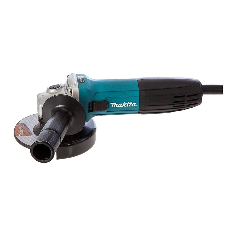
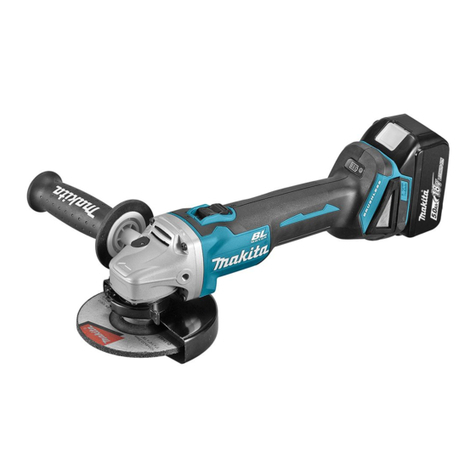
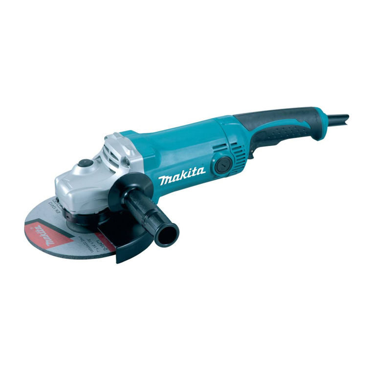
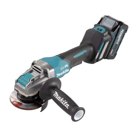
Makita DGA506RME User manual

DGA406
DGA456
DGA506
EN Cordless Angle Grinder INSTRUCTION MANUAL 6
SL Brezžični kotni brusilnik NAVODILA ZA UPORABO 16
SQ Rektikuesi me kënd me
bateri MANUALI I PËRDORIMIT 26
BG Акумулаторен ъглошлайф РЪКОВОДСТВО ЗА
ЕКСПЛОАТАЦИЯ 37
HR Bežična kutna brusilica PRIRUČNIK S UPUTAMA 48
МК Безжична брусилка за агли УПАТСТВО ЗА УПОТРЕБА 58
SR Бежична угаона брусилица УПУТСТВО ЗА УПОТРЕБУ 69
RO Polizor unghiular cu
acumulator MANUAL DE INSTRUCŢIUNI 80
UK Бездротова кутова
шліфувальна машина
ІНСТРУКЦІЯ З
ЕКСПЛУАТАЦІЇ 91
RU Аккумуляторная угловая
шлифмашина
РУКОВОДСТВО ПО
ЭКСПЛУАТАЦИИ 103

1
2
3
Fig.1
1
2
Fig.2
1
Fig.3
1
Fig.4
1
Fig.5
1
Fig.6
Fig.7
1
2
3
Fig.8
2

1
2
3
4
Fig.9
1
2
Fig.10
1
2
4
3
Fig.11
1
2
Fig.12
1
2
3
4
Fig.13
1
2
3
4
Fig.14
1
2
3
Fig.15
Fig.16
3

1
2
3
4
Fig.17
16 mm (5/8″) 16 mm (5/8″)
11
44
23
Fig.18
11
44
23
Fig.19
11
44
23
Fig.20
11
44
23
Fig.21
1
Fig.22
1
Fig.23
1
2
Fig.24
4

1
Fig.25
1
2
5
22
11
12
4
3
5
6
7
8
9
10
13
3
14
5
3
Fig.26
5

6ENGLISH
ENGLISH (Original instructions)
SPECIFICATIONS
Model: DGA406 DGA456 DGA506
Wheel diameter 100mm (4″) 115mm (4-1/2″) 125mm (5″)
Max. wheel thickness 6.4mm
Spindle thread M10 M14 or 5/8″ (country specic)
Rated speed (n) 8,500min-1
Overall length With battery cartridge
BL1815N, BL1820, BL1820B
348mm
With battery cartridge BL1830,
BL1830B, BL1840, BL1840B,
BL1850, BL1850B, BL1860B
362mm
Net weight With battery cartridge
BL1815N, BL1820, BL1820B
2.2kg 2.3kg
With battery cartridge BL1830,
BL1830B, BL1840, BL1840B,
BL1850, BL1850B, BL1860B
2.5kg 2.6kg
Rated voltage D.C.18 V
• Due to our continuing program of research and development, the specications herein are subject to change
without notice.
• Specications and battery cartridge may differ from country to country.
• Weight, with battery cartridge, according to EPTA-Procedure 01/2003
Intended use
The tool is intended for grinding, sanding and cutting of
metal and stone materials without the use of water.
Noise
The typical A-weighted noise level determined accord-
ing to EN60745:
Model DGA456
Sound pressure level (LpA) : 79 dB(A)
Uncertainty (K) : 3 dB(A)
Model DGA506
Sound pressure level (LpA) : 79 dB(A)
Uncertainty (K) : 3dB(A)
The noise level under working may exceed 80 dB (A).
WARNING: Wear ear protection.
Vibration
The vibration total value (tri-axial vector sum) deter-
mined according to EN60745:
Model DGA456
Work mode: surface grinding with normal side grip
Vibration emission (ah, AG) : 6.5 m/s2
Uncertainty (K) : 1.5 m/s2
Work mode: surface grinding with anti vibration side grip
Vibration emission (ah, AG) : 6.0 m/s2
Uncertainty (K) : 1.5 m/s2
Work mode: disc sanding with normal side grip
Vibration emission (ah, DS) : 2.5 m/s2or less
Uncertainty (K) : 1.5 m/s2
Work mode: disc sanding with anti vibration side grip
Vibration emission (ah, DS) : 2.5 m/s2or less
Uncertainty (K) : 1.5 m/s2
Model DGA506
Work mode: surface grinding with normal side grip
Vibration emission (ah, AG) : 6.5 m/s2
Uncertainty (K) : 1.5 m/s2
Work mode: surface grinding with anti vibration side grip
Vibration emission (ah, AG) : 6.0 m/s2
Uncertainty (K) : 1.5 m/s2
Work mode: disc sanding with normal side grip
Vibration emission (ah, DS) : 2.5 m/s2or less
Uncertainty (K) : 1.5 m/s2
Work mode: disc sanding with anti vibration side grip
Vibration emission (ah, DS) : 2.5 m/s2or less
Uncertainty (K) : 1.5 m/s2
NOTE: The declared vibration emission value has
been measured in accordance with the standard test
method and may be used for comparing one tool with
another.
NOTE: The declared vibration emission value
may also be used in a preliminary assessment of
exposure.

7ENGLISH
WARNING: The vibration emission during actual
use of the power tool can differ from the declared
emission value depending on the ways in which the
tool is used.
WARNING: Be sure to identify safety measures
to protect the operator that are based on an estima-
tion of exposure in the actual conditions of use (taking
account of all parts of the operating cycle such as
the times when the tool is switched off and when it is
running idle in addition to the trigger time).
WARNING: The declared vibration emission
value is used for main applications of the power tool.
However if the power tool is used for other applica-
tions, the vibration emission value may be different.
EC Declaration of Conformity
For European countries only
Makita declares that the following Machine(s):
Designation of Machine: Cordless Angle Grinder
Model No./ Type: DGA456, DGA506
Conforms to the following European Directives:
2006/42/EC
They are manufactured in accordance with the following
standard or standardized documents: EN60745
The technical le in accordance with 2006/42/EC is
available from:
Makita, Jan-Baptist Vinkstraat 2, 3070, Belgium
11.8.2015
Yasushi Fukaya
Director
Makita, Jan-Baptist Vinkstraat 2, 3070, Belgium
General power tool safety warnings
WARNING: Read all safety warnings and
all instructions. Failure to follow the warnings and
instructions may result in electric shock, re and/or
serious injury.
Save all warnings and instruc-
tions for future reference.
The term "power tool" in the warnings refers to your
mains-operated (corded) power tool or battery-operated
(cordless) power tool.
Cordless grinder safety warnings
Safety Warnings Common for Grinding, Sanding,
Wire Brushing, or Abrasive Cutting-Off Operations:
1.
This power tool is intended to function as a grinder,
sander, wire brush or cut-off tool. Read all safety
warnings, instructions, illustrations and specica-
tions provided with this power tool. Failure to follow
all instructions listed below may result in electric shock,
re and/or serious injury.
2. Operations such as polishing are not rec-
ommended to be performed with this power tool.
Operations for which the power tool was not designed
may create a hazard and cause personal injury.
3. Do not use accessories which are not speci-
cally designed and recommended by the tool
manufacturer. Just because the accessory can
be attached to your power tool, it does not assure
safe operation.
4. The rated speed of the accessory must be at
least equal to the maximum speed marked on
the power tool. Accessories running faster than
their rated speed can break and y apart.
5. The outside diameter and the thickness of your
accessory must be within the capacity rating
of your power tool. Incorrectly sized accessories
cannot be adequately guarded or controlled.
6. Threaded mounting of accessories must
match the grinder spindle thread. For acces-
sories mounted by anges, the arbour hole of
the accessory must t the locating diameter
of the ange. Accessories that do not match the
mounting hardware of the power tool will run out of
balance, vibrate excessively and may cause loss
of control.
7. Do not use a damaged accessory. Before each
use inspect the accessory such as abrasive
wheels for chips and cracks, backing pad for
cracks, tear or excess wear, wire brush for
loose or cracked wires. If power tool or acces-
sory is dropped, inspect for damage or install
an undamaged accessory. After inspecting and
installing an accessory, position yourself and
bystanders away from the plane of the rotating
accessory and run the power tool at maximum
no-load speed for one minute. Damaged acces-
sories will normally break apart during this test
time.
8. Wear personal protective equipment.
Depending on application, use face shield,
safety goggles or safety glasses. As appro-
priate, wear dust mask, hearing protectors,
gloves and workshop apron capable of stop-
ping small abrasive or workpiece fragments.
The eye protection must be capable of stopping
ying debris generated by various operations.
The dust mask or respirator must be capable of
ltrating particles generated by your operation.
Prolonged exposure to high intensity noise may
cause hearing loss.
9. Keep bystanders a safe distance away from
work area. Anyone entering the work area
must wear personal protective equipment.
Fragments of workpiece or of a broken accessory
may y away and cause injury beyond immediate
area of operation.
10. Hold the power tool by insulated gripping
surfaces only, when performing an operation
where the cutting tool may contact hidden
wiring. Contact with a "live" wire will also make
exposed metal parts of the power tool "live" and
could give the operator an electric shock.
11. Never lay the power tool down until the acces-
sory has come to a complete stop. The spinning
accessory may grab the surface and pull the
power tool out of your control.
12. Do not run the power tool while carrying it at
your side. Accidental contact with the spinning
accessory could snag your clothing, pulling the
accessory into your body.

8ENGLISH
13. Regularly clean the power tool’s air vents. The
motor’s fan will draw the dust inside the housing
and excessive accumulation of powdered metal
may cause electrical hazards.
14. Do not operate the power tool near ammable
materials. Sparks could ignite these materials.
15. Do not use accessories that require liquid
coolants. Using water or other liquid coolants
may result in electrocution or shock.
Kickback and Related Warnings
Kickback is a sudden reaction to a pinched or snagged
rotating wheel, backing pad, brush or any other acces-
sory. Pinching or snagging causes rapid stalling of the
rotating accessory which in turn causes the uncon-
trolled power tool to be forced in the direction opposite
of the accessory’s rotation at the point of the binding.
For example, if an abrasive wheel is snagged or pinched by
the workpiece, the edge of the wheel that is entering into the
pinch point can dig into the surface of the material causing
the wheel to climb out or kick out. The wheel may either jump
toward or away from the operator, depending on direction
of the wheel’s movement at the point of pinching. Abrasive
wheels may also break under these conditions.
Kickback is the result of power tool misuse and/or
incorrect operating procedures or conditions and can be
avoided by taking proper precautions as given below.
1. Maintain a rm grip on the power tool and
position your body and arm to allow you to
resist kickback forces. Always use auxiliary
handle, if provided, for maximum control over
kickback or torque reaction during start-up.
The operator can control torque reactions or kick-
back forces, if proper precautions are taken.
2. Never place your hand near the rotating acces-
sory. Accessory may kickback over your hand.
3. Do not position your body in the area where
power tool will move if kickback occurs.
Kickback will propel the tool in direction opposite
to the wheel’s movement at the point of snagging.
4. Use special care when working corners, sharp
edges etc. Avoid bouncing and snagging the
accessory. Corners, sharp edges or bouncing
have a tendency to snag the rotating accessory
and cause loss of control or kickback.
5. Do not attach a saw chain woodcarving blade
or toothed saw blade. Such blades create fre-
quent kickback and loss of control.
Safety Warnings Specic for Grinding and Abrasive
Cutting-Off Operations:
1. Use only wheel types that are recommended
for your power tool and the specic guard
designed for the selected wheel. Wheels for
which the power tool was not designed cannot be
adequately guarded and are unsafe.
2. The grinding surface of centre depressed
wheels must be mounted below the plane of
the guard lip. An improperly mounted wheel that
projects through the plane of the guard lip cannot
be adequately protected.
3.
The guard must be securely attached to the
power tool and positioned for maximum safety,
so the least amount of wheel is exposed towards
the operator. The guard helps to protect the opera-
tor from broken wheel fragments, accidental contact
with wheel and sparks that could ignite clothing.
4.
Wheels must be used only for recommended
applications. For example: do not grind with the
side of cut-off wheel. Abrasive cut-off wheels are
intended for peripheral grinding, side forces applied
to these wheels may cause them to shatter.
5. Always use undamaged wheel anges that are
of correct size and shape for your selected
wheel. Proper wheel anges support the wheel
thus reducing the possibility of wheel breakage.
Flanges for cut-off wheels may be different from
grinding wheel anges.
6. Do not use worn down wheels from larger
power tools. Wheel intended for larger power tool
is not suitable for the higher speed of a smaller
tool and may burst.
Additional Safety Warnings Specic for Abrasive
Cutting-Off Operations:
1. Do not “jam“ the cut-off wheel or apply exces-
sive pressure. Do not attempt to make an
excessive depth of cut. Overstressing the wheel
increases the loading and susceptibility to twisting
or binding of the wheel in the cut and the possibil-
ity of kickback or wheel breakage.
2. Do not position your body in line with and
behind the rotating wheel. When the wheel, at
the point of operation, is moving away from your
body, the possible kickback may propel the spin-
ning wheel and the power tool directly at you.
3. When wheel is binding or when interrupting
a cut for any reason, switch off the power
tool and hold the power tool motionless until
the wheel comes to a complete stop. Never
attempt to remove the cut-off wheel from the
cut while the wheel is in motion otherwise
kickback may occur. Investigate and take correc-
tive action to eliminate the cause of wheel binding.
4.
Do not restart the cutting operation in the work-
piece. Let the wheel reach full speed and carefully
re-enter the cut. The wheel may bind, walk up or
kickback if the power tool is restarted in the workpiece.
5. Support panels or any oversized workpiece to
minimize the risk of wheel pinching and kick-
back. Large workpieces tend to sag under their
own weight. Supports must be placed under the
workpiece near the line of cut and near the edge
of the workpiece on both sides of the wheel.
6. Use extra caution when making a “pocket cut”
into existing walls or other blind areas. The
protruding wheel may cut gas or water pipes, elec-
trical wiring or objects that can cause kickback.
Safety Warnings Specic for Sanding Operations:
1. Do not use excessively oversized sanding
disc paper. Follow manufacturers recommen-
dations, when selecting sanding paper. Larger
sanding paper extending beyond the sanding
pad presents a laceration hazard and may cause
snagging, tearing of the disc or kickback.
Safety Warnings Specic for Wire Brushing
Operations:
1. Be aware that wire bristles are thrown by the
brush even during ordinary operation. Do not
overstress the wires by applying excessive
load to the brush. The wire bristles can easily
penetrate light clothing and/or skin.

9ENGLISH
2. If the use of a guard is recommended for wire
brushing, do not allow any interference of the
wire wheel or brush with the guard. Wire wheel
or brush may expand in diameter due to work load
and centrifugal forces.
Additional Safety Warnings:
1. When using depressed centre grinding wheels,
be sure to use only berglass-reinforced
wheels.
2. NEVER USE Stone Cup type wheels with this
grinder. This grinder is not designed for these
types of wheels and the use of such a product
may result in serious personal injury.
3. Be careful not to damage the spindle, the
ange (especially the installing surface) or the
lock nut. Damage to these parts could result in
wheel breakage.
4. Make sure the wheel is not contacting the
workpiece before the switch is turned on.
5. Before using the tool on an actual workpiece,
let it run for a while. Watch for vibration or
wobbling that could indicate poor installation
or a poorly balanced wheel.
6. Use the specied surface of the wheel to per-
form the grinding.
7. Do not leave the tool running. Operate the tool
only when hand-held.
8. Do not touch the workpiece immediately after
operation; it may be extremely hot and could
burn your skin.
9. Observe the instructions of the manufacturer
for correct mounting and use of wheels.
Handle and store wheels with care.
10. Do not use separate reducing bushings or
adaptors to adapt large hole abrasive wheels.
11. Use only anges specied for this tool.
12. For tools intended to be tted with threaded
hole wheel, ensure that the thread in the wheel
is long enough to accept the spindle length.
13. Check that the workpiece is properly
supported.
14. Pay attention that the wheel continues to
rotate after the tool is switched off.
15. If working place is extremely hot and humid,
or badly polluted by conductive dust, use a
short-circuit breaker (30 mA) to assure opera-
tor safety.
16. Do not use the tool on any materials contain-
ing asbestos.
17. When use cut-off wheel, always work with
the dust collecting wheel guard required by
domestic regulation.
18. Cutting discs must not be subjected to any
lateral pressure.
19. Do not use cloth work gloves during operation.
Fibers from cloth gloves may enter the tool, which
causes tool breakage.
SAVE THESE INSTRUCTIONS.
WARNING: DO NOT let comfort or familiarity
with product (gained from repeated use) replace
strict adherence to safety rules for the subject
product. MISUSE or failure to follow the safety
rules stated in this instruction manual may cause
serious personal injury.
Important safety instructions for
battery cartridge
1.
Before using battery cartridge, read all instructions
and cautionary markings on (1) battery charger, (2)
battery, and (3) product using battery.
2. Do not disassemble battery cartridge.
3. If operating time has become excessively
shorter, stop operating immediately. It may
result in a risk of overheating, possible burns
and even an explosion.
4. If electrolyte gets into your eyes, rinse them
out with clear water and seek medical atten-
tion right away. It may result in loss of your
eyesight.
5. Do not short the battery cartridge:
(1) Do not touch the terminals with any con-
ductive material.
(2) Avoid storing battery cartridge in a con-
tainer with other metal objects such as
nails, coins, etc.
(3) Do not expose battery cartridge to water
or rain.
A battery short can cause a large current
ow, overheating, possible burns and even a
breakdown.
6. Do not store the tool and battery cartridge in
locations where the temperature may reach or
exceed 50 °C (122 °F).
7. Do not incinerate the battery cartridge even if
it is severely damaged or is completely worn
out. The battery cartridge can explode in a re.
8. Be careful not to drop or strike battery.
9. Do not use a damaged battery.
10.
The contained lithium-ion batteries are subject to
the Dangerous Goods Legislation requirements.
For commercial transports e.g. by third parties,
forwarding agents, special requirement on pack-
aging and labeling must be observed.
For preparation of the item being shipped, consult-
ing an expert for hazardous material is required.
Please also observe possibly more detailed
national regulations.
Tape or mask off open contacts and pack up the
battery in such a manner that it cannot move
around in the packaging.
11. Follow your local regulations relating to dis-
posal of battery.
SAVE THESE INSTRUCTIONS.
CAUTION: Only use genuine Makita batteries.
Use of non-genuine Makita batteries, or batteries that
have been altered, may result in the battery bursting
causing res, personal injury and damage. It will
also void the Makita warranty for the Makita tool and
charger.

10 ENGLISH
Tips for maintaining maximum
battery life
1.
Charge the battery cartridge before completely dis-
charged. Always stop tool operation and charge the
battery cartridge when you notice less tool power.
2. Never recharge a fully charged battery car-
tridge. Overcharging shortens the battery
service life.
3.
Charge the battery cartridge with room temperature
at 10 °C - 40 °C (50 °F - 104 °F). Let a hot battery
cartridge cool down before charging it.
4. Charge the battery cartridge if you do not use
it for a long period (more than six months).
FUNCTIONAL
DESCRIPTION
CAUTION: Always be sure that the tool is
switched off and the battery cartridge is removed
before adjusting or checking function on the tool.
Installing or removing battery
cartridge
CAUTION: Always switch off the tool before
installing or removing of the battery cartridge.
CAUTION:
Hold the tool and the battery cartridge
rmly when installing or removing battery cartridge.
Failure to hold the tool and the battery cartridge rmly may
cause them to slip off your hands and result in damage to
the tool and battery cartridge and a personal injury.
► Fig.1: 1. Red indicator 2. Button 3. Battery cartridge
To remove the battery cartridge, slide it from the tool
while sliding the button on the front of the cartridge.
To install the battery cartridge, align the tongue on the
battery cartridge with the groove in the housing and slip
it into place. Insert it all the way until it locks in place
with a little click. If you can see the red indicator on the
upper side of the button, it is not locked completely.
CAUTION: Always install the battery cartridge
fully until the red indicator cannot be seen. If not,
it may accidentally fall out of the tool, causing injury to
you or someone around you.
CAUTION: Do not install the battery cartridge
forcibly. If the cartridge does not slide in easily, it is
not being inserted correctly.
Indicating the remaining battery
capacity
Only for battery cartridges with "B" at the end of the
model number
► Fig.2: 1. Indicator lamps 2. Check button
Press the check button on the battery cartridge to indi-
cate the remaining battery capacity. The indicator lamps
light up for few seconds.
Indicator lamps Remaining
capacity
Lighted Off Blinking
75% to 100%
50% to 75%
25% to 50%
0% to 25%
Charge the
battery.
The battery
may have
malfunctioned.
NOTE: Depending on the conditions of use and the
ambient temperature, the indication may differ slightly
from the actual capacity.
Indicating the remaining battery
capacity
Country specic
When you turn the tool on, the battery indicator shows
the remaining battery capacity.
► Fig.3: 1. Battery indicator
The remaining battery capacity is shown as the follow-
ing table.
Battery indicator status Remaining
battery
capacity
On Off Blinking
50% - 100%
20% - 50%
0% - 20%
Charge the
battery
Tool / battery protection system
The tool is equipped with a tool/battery protection
system. This system automatically cuts off power to
the motor to extend tool and battery life. The tool will
automatically stop during operation if the tool or battery
is placed under one of the following conditions. In some
conditions, the indicators light up.

11 ENGLISH
Overload protection
When the tool is operated in a manner that causes it to
draw an abnormally high current, the tool automatically
stops without any indication. In this situation, turn the
tool off and stop the application that caused the tool to
become overloaded. Then turn the tool on to restart.
Overheat protection
When the tool is overheated, the tool stops automati-
cally and the battery indicator shows following state. In
this situation, let the tool cool before turning the tool on
again.
On Blinking
If the tool does not start, the battery may be overheated.
In this situation, let the battery cool before starting the
tool again.
Overdischarge protection
When the battery capacity is not enough, the tool stops
automatically. In this case, remove the battery from the
tool and charge the battery.
Releasing protection lock
When the protection system works repeatedly, the tool
is locked and the battery indicator shows the following
state.
In this situation, the tool does not start even if turning
the tool off and on. To release the protection lock,
remove the battery, set it to the battery charger and wait
until the charging nishes.
On Off Blinking
Shaft lock
Press the shaft lock to prevent spindle rotation when
installing or removing accessories.
► Fig.4: 1. Shaft lock
NOTICE: Never actuate the shaft lock when the
spindle is moving. The tool may be damaged.
Switch action
CAUTION: Before installing the battery car-
tridge into the tool, always check to see that the
slide switch actuates properly and returns to the
"OFF" position when the rear of the slide switch
is depressed.
CAUTION: Switch can be locked in "ON" posi-
tion for ease of operator comfort during extended
use. Apply caution when locking tool in "ON"
position and maintain rm grasp on tool.
To start the tool, slide the slide switch toward the “I
(ON)” position by pushing the rear of the slide switch.
For continuous operation, press the front of the slide
switch to lock it.
To stop the tool, press the rear of the slide switch, then
slide it toward the “O (OFF)” position.
► Fig.5: 1. Slide switch
Automatic speed change function
► Fig.6: 1. Mode indicator
Mode indicator status Operation mode
High speed mode
High torque mode
This tool has "high speed mode" and "high torque mode". It
automatically changes operation mode depending on the work
load. When mode indicator lights up during operation, the tool
is in high torque mode.
Accidental re-start preventive
function
Even if the battery cartridge is installed on the tool with
the slide switch in the "I (ON)" position, the tool does
not start.
To start the tool, rst slide the slide switch toward the
"O (OFF)" position and then slide it toward the "I (ON)"
position.
Electronic torque control function
The tool electronically detects situations where the wheel or
accessory may be at risk to be bound. In the situation, the
tool is automatically shut off to prevent further rotation of the
spindle (it does not prevent kickback).
To restart the tool, switch off the tool rst, remove the
cause of sudden drop in the rotation speed, and then
turn the tool on.
Soft start feature
Soft start feature reduces starting reaction.
Electric brake
Electric brake is activated after the tool is switched off.
The brake does not work when the power supply is shut
down, such as the battery is removed accidentally, with
the switch still on.

12 ENGLISH
ASSEMBLY
CAUTION: Always be sure that the tool is
switched off and the battery cartridge is removed
before adjusting or checking function on the tool.
Installing side grip (handle)
CAUTION: Always be sure that the side grip is
installed securely before operation.
Screw the side grip securely on the position of the tool
as shown in the gure.
► Fig.7
Installing or removing wheel guard
(For depressed center wheel, ap
disc, ex wheel, wire wheel brush
/ abrasive cut-off wheel, diamond
wheel)
WARNING:
When using a depressed center wheel,
ap disc, ex wheel or wire wheel brush, the wheel guard
must be tted on the tool so that the closed side of the
guard always points toward the operator.
WARNING: When using an abrasive cut-off
/ diamond wheel, be sure to use only the special
wheel guard designed for use with cut-off wheels.
(In some European countries, when using a diamond
wheel, the ordinary guard can be used. Follow the
regulations in your country.)
For tool with locking screw type
wheel guard
Mount the wheel guard with the protrusions on the
wheel guard band aligned with the notches on the bear-
ing box. Then rotate the wheel guard to such an angle
that it can protect the operator according to work. Be
sure to tighten the screw securely.
To remove wheel guard, follow the installation proce-
dure in reverse.
► Fig.8: 1. Wheel guard 2. Bearing box 3. Screw
For tool with clamp lever type wheel
guard
Loosen the screw, and then pull the lever in the direc-
tion of the arrow. Mount the wheel guard with the protru-
sions on the wheel guard band aligned with the notches
on the bearing box. Then rotate the wheel guard to such
an angle that it can protect the operator according to
work.
► Fig.9: 1. Wheel guard 2. Bearing box 3. Screw
4. Lever
Pull the lever in direction of the arrow. Then tighten the
wheel guard with fastening the screw. Be sure to tighten
the screw securely. The setting angle of the wheel
guard can be adjusted with the lever.
► Fig.10: 1. Screw 2. Lever
To remove wheel guard, follow the installation proce-
dure in reverse.
Installing or removing depressed
center wheel or ap disc
Optional accessory
WARNING: When using a depressed center
wheel or ap disc, the wheel guard must be tted
on the tool so that the closed side of the guard
always points toward the operator.
CAUTION: Make sure that the mounting part
of the inner ange ts into the inner diameter of
the depressed center wheel / ap disc perfectly.
Mounting the inner ange on the wrong side may
result in the dangerous vibration.
Mount the inner ange onto the spindle.
Make sure to t the dented part of the inner ange onto
the straight part at the bottom of the spindle.
Fit the depressed center wheel / ap disc on the inner
ange and screw the lock nut onto the spindle.
► Fig.11: 1. Lock nut 2. Depressed center wheel
3. Inner ange 4. Mounting part
To tighten the lock nut, press the shaft lock rmly so
that the spindle cannot revolve, then use the lock nut
wrench and securely tighten clockwise.
► Fig.12: 1. Lock nut wrench 2. Shaft lock
To remove the wheel, follow the installation procedure
in reverse.
Installing or removing ex wheel
Optional accessory
WARNING: Always use supplied guard when
ex wheel is on tool. Wheel can shatter during use
and guard helps to reduce chances of personal injury.
► Fig.13: 1. Lock nut 2. Flex wheel 3. Back up pad
4. Inner ange
Follow instructions for depressed center wheel but also
use back up pad over wheel. See order of assembly on
accessories page in this manual.
Installing or removing abrasive disc
Optional accessory
NOTE: Use sander accessories specied in this man-
ual. These must be purchased separately.
For 100 mm (4″) model
► Fig.14: 1. Sanding lock nut 2. Abrasive disc
3. Rubber pad 4. Inner ange
1. Mount the inner ange onto the spindle.
2. Mount the rubber pad onto the spindle.
3. Fit the disc on the rubber pad and screw the sand-
ing lock nut onto the spindle.
4.
Hold the spindle with the shaft lock, and securely tighten
the sanding lock nut clockwise with the lock nut wrench.
To remove the disc, follow the installation procedure in reverse.

13 ENGLISH
For 115 mm (4 - 1/2″) / 125 mm (5″)
model
► Fig.15: 1. Sanding lock nut 2. Abrasive disc
3. Rubber pad
1. Mount the rubber pad onto the spindle.
2. Fit the disc on the rubber pad and screw the sand-
ing lock nut onto the spindle.
3. Hold the spindle with the shaft lock, and securely
tighten the sanding lock nut clockwise with the lock nut
wrench.
To remove the disc, follow the installation procedure in
reverse.
OPERATION
WARNING: It should never be necessary to
force the tool. The weight of the tool applies ade-
quate pressure. Forcing and excessive pressure
could cause dangerous wheel breakage.
WARNING: ALWAYS replace wheel if tool is
dropped while grinding.
WARNING: NEVER bang or hit grinding disc
or wheel onto work.
WARNING: Avoid bouncing and snagging
the wheel, especially when working corners,
sharp edges etc. This can cause loss of control and
kickback.
WARNING: NEVER use tool with wood cutting
blades and other saw blades. Such blades when
used on a grinder frequently kick and cause loss of
control leading to personal injury.
CAUTION: Never switch on the tool when it
is in contact with the workpiece, it may cause an
injury to operator.
CAUTION: Always wear safety goggles or a
face shield during operation.
CAUTION: After operation, always switch off
the tool and wait until the wheel has come to a
complete stop before putting the tool down.
CAUTION: ALWAYS hold the tool rmly with
one hand on housing and the other on the side
handle.
Grinding and sanding operation
► Fig.16
Turn the tool on and then apply the wheel or disc to the
workpiece.
In general, keep the edge of the wheel or disc at an
angle of about 15° to the workpiece surface.
During the break-in period with a new wheel, do not
work the grinder in forward direction or it may cut into
the workpiece. Once the edge of the wheel has been
rounded off by use, the wheel may be worked in both
forward and backward direction.
Operation with abrasive cut-off /
diamond wheel
Optional accessory
WARNING: When using an abrasive cut-off
/ diamond wheel, be sure to use only the special
wheel guard designed for use with cut-off wheels.
(In some European countries, when using a diamond
wheel, the ordinary guard can be used. Follow the
regulations in your country.)
WARNING: NEVER use cut-off wheel for side
grinding.
WARNING:
Do not "jam" the wheel or apply
excessive pressure. Do not attempt to make an exces-
sive depth of cut. Overstressing the wheel increases the
loading and susceptibility to twisting or binding of the wheel
in the cut and the possibility of kickback, wheel breakage
and overheating of the motor may occur.
WARNING: Do not start the cutting operation
in the workpiece. Let the wheel reach full speed
and carefully enter into the cut moving the tool
forward over the workpiece surface. The wheel
may bind, walk up or kickback if the power tool is
started in the workpiece.
WARNING: During cutting operations, never
change the angle of the wheel. Placing side pres-
sure on the cut-off wheel (as in grinding) will cause
the wheel to crack and break, causing serious per-
sonal injury.
WARNING: A diamond wheel shall be oper-
ated perpendicular to the material being cut.
► Fig.17: 1. Lock nut 2. Abrasive cut-off wheel / dia-
mond wheel 3. Inner ange 4. Wheel guard
for abrasive cut-off wheel / diamond wheel
As for the installation, follow the instructions for
depressed center wheel.
The direction for mounting the lock nut and the
inner ange varies by wheel type and thickness.
Refer to the following gures.
For 100 mm (4″) model
When installing the abrasive cut-off wheel:
► Fig.18: 1. Lock nut 2. Abrasive cut-off wheel
(Thinner than 4mm (5/32")) 3. Abrasive cut-
off wheel (4mm (5/32") or thicker) 4. Inner
ange
When installing the diamond wheel:
► Fig.19: 1. Lock nut 2. Diamond wheel (Thinner
than 4mm (5/32″)) 3. Diamond wheel (4mm
(5/32″) or thicker) 4. Inner ange
For 115 mm (4 - 1/2″) / 125 mm (5″)
model
When installing the abrasive cut-off wheel:
► Fig.20: 1. Lock nut 2. Abrasive cut-off wheel
(Thinner than 4mm (5/32")) 3. Abrasive cut-
off wheel (4mm (5/32") or thicker) 4. Inner
ange

14 ENGLISH
When installing the diamond wheel:
► Fig.21: 1. Lock nut 2. Diamond wheel (Thinner
than 4mm (5/32″)) 3. Diamond wheel (4mm
(5/32″) or thicker) 4. Inner ange
Operation with wire cup brush
Optional accessory
CAUTION: Check operation of brush by run-
ning tool with no load, insuring that no one is in
front of or in line with brush.
CAUTION: Do not use brush that is damaged,
or which is out of balance. Use of damaged brush
could increase potential for injury from contact with
broken brush wires.
► Fig.22: 1. Wire cup brush
Remove the battery cartridge from the tool and place it
upside down allowing easy access to spindle.
Remove any accessories on spindle. Thread wire cup
brush onto spindle and tighten with supplied wrench.
NOTICE: Avoid applying too much pressure
which causes over bending of wires when using
brush. It may lead to premature breakage.
Operation with wire wheel brush
Optional accessory
CAUTION: Check operation of wire wheel
brush by running tool with no load, insuring that
no one is in front of or in line with the wire wheel
brush.
CAUTION: Do not use wire wheel brush that
is damaged, or which is out of balance. Use of
damaged wire wheel brush could increase potential
for injury from contact with broken wires.
CAUTION: ALWAYS use guard with wire
wheel brushes, assuring diameter of wheel ts
inside guard. Wheel can shatter during use and
guard helps to reduce chances of personal injury.
► Fig.23: 1. Wire wheel brush
Remove the battery cartridge from the tool and place it
upside down allowing easy access to spindle.
Remove any accessories on spindle. Thread wire wheel
brush onto spindle and tighten with the wrenches.
NOTICE: Avoid applying too much pressure
which causes over bending of wires when
using wire wheel brush. It may lead to premature
breakage.
MAINTENANCE
CAUTION: Always be sure that the tool is
switched off and the battery cartridge is removed
before attempting to perform inspection or
maintenance.
NOTICE: Never use gasoline, benzine, thinner,
alcohol or the like. Discoloration, deformation or
cracks may result.
Air vent cleaning
The tool and its air vents have to be kept clean.
Regularly clean the tool's air vents or whenever the
vents start to become obstructed.
► Fig.24: 1. Exhaust vent 2. Inhalation vent
Remove the dust cover from inhalation vent and clean it
for smooth air circulation.
► Fig.25: 1. Dust cover
NOTE: Clean out the dust cover when it is clogged
with dust or foreign matters. Continuing operation
with a clogged dust cover may damage the tool.
OPTIONAL ACCESSORIES
CAUTION: These accessories or attachments are recommended for use with your Makita tool spec-
ied in this manual. The use of any other accessories or attachments might present a risk of injury to persons.
Only use accessory or attachment for its stated purpose.
If you need any assistance for more details regarding these accessories, ask your local Makita Service Center.
• Makita genuine battery and charger
► Fig.26

15 ENGLISH
-100 mm (4″) model 115 mm (4-1/2″) model 125 mm (5″) model
1Grip 36
2Wheel Guard (for grinding wheel)
3Inner ange
4Depressed center wheel / Flap disc
5Lock nut
6Back up pad
7Flex wheel
8Inner ange and rubber pad 76 Rubber pad 100 Rubber pad 115
9Abrasive disc
10 Sanding lock nut
11 Wire wheel brush
12 Wire cup brush
13 Wheel Guard (for cut-off wheel) *1
14 Abrasive cut-off wheel / Diamond wheel
-Lock nut wrench
NOTE: *1 In some European countries, when using a diamond wheel, the ordinary guard can be used instead of the
special guard covering the both side of the wheel. Follow the regulations in your country.
NOTE: Some items in the list may be included in the tool package as standard accessories. They may differ from
country to country.

16 SLOVENŠČINA
SLOVENŠČINA (Originalna navodila)
TEHNIČNI PODATKI
Model: DGA406 DGA456 DGA506
Premer rezalne plošče 100 mm (4″) 115 mm (4-1/2″) 125 mm (5″)
Največja debelina plošče 6,4 mm
Navoj vretena M10 M14 ali 5/8″ (odvisno od države)
Nazivna hitrost (n) 8.500 min-1
Celotna dolžina Uporablja se akumulatorska
baterija z oznako BL1815N,
BL1820, BL1820B
348 mm
Uporablja se akumulatorska
baterija z oznako BL1830,
BL1830B, BL1840, BL1840B,
BL1850, BL1850B, BL1860B
362 mm
Neto teža Uporablja se akumulatorska
baterija z oznako BL1815N,
BL1820, BL1820B
2,2 kg 2,3 kg
Uporablja se akumulatorska
baterija z oznako BL1830,
BL1830B, BL1840, BL1840B,
BL1850, BL1850B, BL1860B
2,5 kg 2,6 kg
Nazivna napetost D.C. 18 V
• Ker nenehno opravljamo raziskave in razvijamo svoje izdelke, se lahko tehnični podatki v tem dokumentu
spremenijo brez obvestila.
• Tehnični podatki in baterijski vložki se lahko razlikujejo glede na državo uporabe izdelka.
• Teža skupaj z baterijskim vložkom v skladu s postopkom EPTA 01/2003
Predvidena uporaba
Stroj je namenjen za brušenje, glajenje in rezanje
kovine in kamna brez uporabe vode.
Hrup
Običajna A-ovrednotena raven hrupa v skladu z
EN60745:
Model DGA456
Raven zvočnega tlaka (LpA): 79 dB (A)
Odstopanje (K): 3 dB (A)
Model DGA506
Raven zvočnega tlaka (LpA): 79 dB (A)
Odstopanje (K): 3 dB (A)
Nivo hrupa med delom lahko preseže 80 dB (A).
OPOZORILO: Uporabljajte zaščito za sluh.
Vibracije
Skupne vrednosti vibracij (vektorska vsota treh osi) v
skladu z EN60745:
Model DGA456
Delovni način: brušenje površin z običajnim stranskim
držalom
Oddajanje tresljajev (ah, AG): 6,5 m/s2
Odstopanje (K): 1,5 m/s2
Delovni način: brušenje površin z antivibracijskim
držalom
Oddajanje tresljajev (ah, AG): 6,0 m/s2
Odstopanje (K): 1,5 m/s2
Delovni način: peskanje s ploščo z običajnim stranskim
držalom
Oddajanje tresljajev (ah, DS): 2,5 m/s2 ali manj
Odstopanje (K): 1,5 m/s2
Delovni način: peskanje s ploščo z antivibracijskim
držalom
Oddajanje tresljajev (ah, DS): 2,5 m/s2 ali manj
Odstopanje (K): 1,5 m/s2
Model DGA506
Delovni način: brušenje površin z običajnim stranskim
držalom
Oddajanje tresljajev (ah, AG): 6,5 m/s2
Odstopanje (K): 1,5 m/s2
Delovni način: brušenje površin z antivibracijskim
držalom
Oddajanje tresljajev (ah, AG): 6,0 m/s2
Odstopanje (K): 1,5 m/s2
Delovni način: peskanje s ploščo z običajnim stranskim
držalom
Oddajanje tresljajev (ah, DS): 2,5 m/s2 ali manj
Odstopanje (K): 1,5 m/s2
Delovni način: peskanje s ploščo z antivibracijskim
držalom
Oddajanje tresljajev (ah, DS): 2,5 m/s2 ali manj
Odstopanje (K): 1,5 m/s2
OPOMBA: Navedena vrednost oddajanja vibracij
je bila izmerjena v skladu s standardnimi metodami
testiranja in se lahko uporablja za primerjavo orodij.
OPOMBA: Navedena vrednost oddajanja vibra-
cij se lahko uporablja tudi pri predhodni oceni
izpostavljenosti.

17 SLOVENŠČINA
OPOZORILO: Oddajanje vibracij med dejansko
uporabo električnega orodja se lahko razlikuje od
navedene vrednosti oddajanja, odvisno od načina
uporabe orodja.
OPOZORILO: Upravljavec mora za lastno zaš-
čito poznati varnostne ukrepe, ki temeljijo na oceni
izpostavljenosti v dejanskih pogojih uporabe (poleg
časa proženja je treba upoštevati celoten delovni
cikel, vključno s časom, ko je orodje izklopljeno, in
časom, ko deluje v prostem teku).
OPOZORILO:
Navedena vrednost oddajanja
vibracij se uporablja za glavno uporabo električnega
orodja. Vendar če električno orodje uporabljate za druge
namene, se lahko vrednosti oddajanja vibracij razlikujejo.
ES Izjava o skladnosti
Samo za evropske države
Družba Makita izjavlja, da so naslednji izdelki:
Oznaka stroja: Brezžični kotni brusilnik
Številka/tip modela: DGA456, DGA506
skladni z naslednjimi evropskimi direktivami:
2006/42/ES
Izdelani so v skladu z naslednjim standardom ali stan-
dardiziranimi dokumenti: EN60745
Tehnična dokumentacija v skladu z direktivo 2006/42/
ES je na voljo na naslovu:
Makita, Jan-Baptist Vinkstraat 2, 3070, Belgija
11.8.2015
Yasushi Fukaya
Direktor
Makita, Jan-Baptist Vinkstraat 2, 3070, Belgija
Splošna varnostna opozorila za
električno orodje
OPOZORILO: Preberite vsa varnostna opo-
zorila in navodila. Neupoštevanje opozoril in navodil
lahko privede do električnega udara, požara in/ali
resnih telesnih poškodb.
Shranite vsa opozorila in navo-
dila za poznejšo uporabo.
Izraz „električno orodje“ v opozorilih se nanaša na vaše
električno orodje (s kablom) ali baterijsko električno
orodje (brez kabla).
Varnostna opozorila pri uporabi
brezžičnega brusilnika
Varnostna opozorila za brušenje, glajenje, žično
ščetkanje ali rezanje:
1. Kotni brusilnik je namenjen za brušenje, glaje-
nje, žično ščetkanje ali rezanje. Preberite vsa
varnostna opozorila in navodila s slikami in
tehničnimi podatki, ki so dobavljeni skupaj z
električnim orodjem. Ob neupoštevanju spodaj
navedenih navodil obstaja nevarnost električnega
udara, požara in/ali hudih telesnih poškodb.
2. Kotni brusilnik ni primeren za poliranje.
Izvajanje opravil, za katere električno orodje ni
bilo zasnovano, je nevarno in lahko povzroči hude
telesne poškodbe.
3.
Uporabljajte le nastavke, ki jih je posebej za to
orodje zasnoval oz. jih priporoča proizvajalec. Če je
nastavek mogoče pritrditi na električno orodje, to še ne
pomeni, da je uporaba tega nastavka varna.
4.
Nazivno število vrtljajev nastavka mora ustrezati
vsaj največjemu številu vrtljajev, ki je označeno
na električnem orodju. Nastavek, ki se vrti hitreje od
nazivnega števila vrtljajev, se lahko zlomi in razleti.
5. Zunanji premer in debelina nastavka morata
ustrezati nazivni moči električnega orodja.
Nastavka neustrezne velikosti ni mogoče pravilno
zavarovati s ščitniki ali ga povsem nadzorovati.
6.
Pritrditev nastavkov z navoji se mora prilegati navo-
jem vretena brusilnika. Pri nastavkih, nameščenih
s prirobnicami, se morajo osne luknje nastavkov
natančno prilegati premeru prirobnice. Nastavkov,
ki se ne ujemajo, ni mogoče ustrezno namestiti na
električno orodje, kar lahko povzroči neuravnoteženost,
čezmerno vibriranje in izgubo nadzora.
7.
Ne uporabljajte poškodovanih nastavkov. Pred
vsako uporabo preverite nastavke (npr. plošče), če
se morda niso odkrušile, če brusilni krožniki niso
počeni, pretrgani ali čezmerno obrabljeni ali če so
na žičnih ščetkah ohlapne ali počene žice. Če pade
električno orodje ali nastavek na tla, preverite,
če so nastale poškodbe, in po potrebi namestite
nepoškodovani nastavek. Po pregledu in name-
stitvi nastavka se postavite izven ravnine vrtenja
nastavka in opozorite osebe v vaši bližini, naj se
oddaljijo, ter vključite orodje in ga pustite teči eno
minuto brez obremenitve. Med tem preizkusom poš-
kodovani nastavki običajno počijo.
8.
Uporabljajte osebna zaščitna sredstva. Odvisno od
dela, ki ga opravljate, uporabljajte zaščitno masko
za obraz in oči ali zaščitna očala. Če je potrebno,
uporabljajte zaščitno masko proti prahu, glušnike,
rokavice ali predpasnik za zaščito pred drobci mate-
riala. Zaščita za oči mora zadržati leteče drobce, ki so
prisotni pri različnih načinih dela. Protiprašna maska ali
maska za zaščito dihal mora zadržati prah, ki nastaja
med delom. Izpostavljanje hrupu lahko povzroči izgubo
sluha.
9. Pri delu poskrbite, da bodo druge osebe varno
oddaljene od delovnega območja. V delovno
območje lahko vstopajo samo osebe z ustre-
zno osebno zaščitno opremo. Leteči drobci
materiala obdelovanca ali počenega nastavka so
nevarni in lahko povzročijo poškodbe tudi izven
delovnega območja.
10. Če obstaja nevarnost, da bi z rezalnim orodjem
prerezali skrito električno napeljavo, držite
električno orodje samo na izoliranih držalnih
površinah. Če pride do stika z vodniki pod nape-
tostjo, so pod napetostjo vsi neizolirani kovinski
deli električnega orodja, zaradi česar lahko upo-
rabnik utrpi električni udar.
11. Ne odlagajte električnega orodja iz rok, dok-
ler se nameščeni nastavek ne neha vrteti.
Nastavek, ki se še vedno vrti, lahko pride v stik
z odlagalno površino in povzroči izgubo nadzora
nad električnim orodjem.

18 SLOVENŠČINA
12. Ne puščajte električnega orodja vključenega
brez nadzora. Vrteči se nastavek se lahko nepri-
čakovano zaplete v vašo obleko in vas poškoduje.
13. Redno čistite hladilne reže električnega orodja.
Ventilator motorja vsesava v ohišje prah, ki
povzroča škodljivo kopičenje prahu in s tem nevar-
nost električne okvare.
14. Ne uporabljajte električnega orodja v bližini
gorljivih snovi. Gorljive snovi se lahko vnamejo
zaradi iskrenja.
15. Ne uporabljajte nastavkov, ki so predvideni
za uporabo s tekočim hladilnim sredstvom.
Uporaba vode ali drugih tekočin za hlajenje lahko
povzroči električni udar.
Opozorila v zvezi s povratnim udarcem
Povratni udarec je nenadna reakcija, če se stisne ali zagozdi
vrteča se plošča, brusilni krožnik, ščetka ali drug nastavek.
Blokada ali zagozdenje namreč povzroči hitro zaustavitev
vrtečih se delov orodja, pri čemer električno orodje sune v
obratno smer od smeri gibanja vrtečih se delov.
Če pride na primer do blokade abrazivne plošče v
obdelovancu, lahko rob v točki zagozdenja zareže v
površino, pri tem pa nastala sila rezalno ploščo odbije
od materiala. Rezalna plošča lahko odskoči bodisi proti
vam ali v nasprotni smeri, kar je odvisno od smeri vode-
nja rezalne plošče v točki zagozdenja. Abrazivna plošča
se lahko pod temi pogoji tudi zlomi.
Povratni udarec je posledica nestrokovnega ravnanja z
električnim orodjem ali neugodnih okoliščin. Preprečite
ga lahko z upoštevanjem spodaj navedenih opozoril.
1.
Električno orodje držite s trdnim prijemom in se
postavite v takšen položaj, da lahko prestrežete
sile povratnega udarca. Če je na električno orodje
mogoče namestiti dodatni ročaj, ga tudi upo-
rabljajte, saj vam omogoča najboljši nadzor nad
povratnimi udarci ali reakcijskim vrtilnim momen-
tom. Reakcijske vrtilne momente ali povratne udarce je
mogoče učinkovito preprečiti z upoštevanjem previdno-
stnih ukrepov.
2. Ne približujte rok vrtečim se delom električ-
nega orodja. Nameščeni nastavek lahko udari
nazaj prek vaše roke.
3. S telesom se postavite stran od smeri, v katero
orodje lahko skoči v primeru, da pride do
povratnega udarca. Povratni udarec sunkovito
potisne orodje v nasprotni smeri vrtenja rezalne
plošče v točki zagozdenja.
4. Pri obdelavi vogalov, ostrih robov ipd. je
potrebna večja previdnost. Izogibajte se polo-
žajem, v katerih lahko orodje odskoči iz obde-
lovanca ali se zagozdi. V vogalih in na ostrih
robovih obstaja povečana nevarnost povratnega
sunka ali zagozdenja nastavka. Posledica tega je
lahko izguba nadzora ali povratni udarec.
5. Ne uporabljajte verižnih ali nazobčanih žagi-
nih listov. Tovrstna orodja pogosto povzročijo
povratni udarec ali izgubo nadzora nad električnim
orodjem.
Varnostna opozorila pri izvajanju brušenja in
rezanja:
1. Uporabljajte samo plošče, ki jih za vaše orodje
in ščitnik posebej priporoča proizvajalec.
Plošče, ki niso posebej namenjene za delo z
vašim orodjem, ni možno ustrezno namestiti, zato
je njihova uporaba lahko nevarna.
2. Površino za brušenje plošč z ugreznjenim
centrom je treba namestiti pod ploskvijo ščit-
nika. Nepravilno nameščene plošče, ki gleda prek
ravnine ščitnika, ni mogoče zadostno zaščititi.
3. Za zagotavljanje maksimalne varnosti pri delu
mora biti ščitnik rezila pravilno nameščen
in tako ustrezno zakrivati kar največ plošče
na delu, obrnjenem proti uporabniku. Ščitnik
varuje uporabnika pred izmetom odlomljenih
delcev in stikom s ploščo ter iskrenja, ki lahko
povzroči vžig oblačil.
4. Rezalne plošče se lahko uporabljajo le za pri-
poročene naprave. Primer: ne uporabljajte jih
za brušenje s stransko ploskvijo. Namenjene so
brušenju z robom rezila. Pri izvajanju bočne sile
na rezalno ploščo lahko ta poči.
5. Uporabljajte samo nepoškodovane prirobnice
plošč, ki po dimenziji in obliki ustrezajo upo-
rabljeni plošči. Ustrezne prirobnice podpirajo
ploščo in zmanjšujejo nevarnost zloma plošče.
Prirobnice za rezalne plošče se lahko razlikujejo
od prirobnic plošč.
6. Ne uporabljajte izrabljenih rezalnih plošč, ki
ste jih predhodno uporabljali na večjih električ-
nih orodjih. Plošče večjih električnih orodij niso
primerne za višje število obratov na manjših orodij
in lahko zato počijo.
Dodatna varnostna opozorila pri izvajanju brušenja
in rezanja:
1. Rezalne plošče ne „blokirajte“ ali preobreme-
njujte. Ne skušajte narediti preglobokih rezov.
Preobremenjevanje plošče povečuje možnost
zvijanja ali zagozdenja plošče v obdelovancu ter s
tem možnost povratnega udarca ali zloma plošče.
2. Ne postavljajte se v položaje, v katerih ste v
primeru povratnega udarca lahko izpostavljeni
sunku električnega orodja. Ko se plošča med
delovanjem premika stran od vašega telesa, lahko
eventualni povratni udarec potisne vrtečo se plo-
ščo in električno orodje neposredno v upravljavca.
3. Če je rezalna plošča ovirana ali če iz katerega
koli razloga rezanje prekinete, držite elek-
trično orodje pri miru, dokler se rezalna plo-
šča popolnoma ne ustavi. Nikoli ne skušajte
odstraniti rezalne plošče iz obdelovanca, dok-
ler se plošča še vrti. Preverite in odpravite vzrok
oviranja rezalne plošče.
4. Rezanja ne začnite ponovno v obdelovancu.
Najprej počakajte, da plošča doseže polno hit-
rost, nato pa pazljivo začnite ponovno rezati.
Če začnete z rezanjem v obdelovancu, se lahko
rezalna plošča zagozdi, lahko pa pride tudi do
povratnega udarca.
5. Pod plošče in velike obdelovance postavite
podporo, da zmanjšate možnost zagozdenja
rezalne plošče ali povratnega udarca. Veliki
obdelovanci se lahko zaradi lastne teže povesijo.
Pod obdelovance je treba poleg linije reza in poleg
roba obdelovanca na obeh straneh plošče posta-
viti podporo.
6. Bodite še posebej pozorni, ko v obstoječe
zidove ali druge slepe točke izvajate „slepe
reze“. Rezalna plošča lahko zadene v plinske,
vodovodne ali električne napeljave ali predmete, ki
lahko povzročijo povratni udarec.

19 SLOVENŠČINA
Varnostna opozorila za brušenje:
1. Ne uporabljajte prevelikega brusnega papirja.
Pri izbiri brusnega papirja upoštevajte priporo-
čile proizvajalca. Večji brusni papir, ki sega prek
brusilne blazinice, predstavlja nevarnost pretrga
in lahko povzroči zagozditev, trganje ali povratni
udarec rezalne plošče.
Varnostna opozorila za žično ščetkanje:
1. Žice ščetke lahko med delovanjem odpadajo.
Ne izvajajte čezmernega pritiska na žice, da jih
ne preobremenite. Žice ščetke enostavno prod-
rejo v lahka oblačila in/ali kožo.
2. Če je za žično ščetkanje priporočena uporaba
ščitnika zagotovite, da se žična plošča ali
ščetka ne dotika ščitnika. Zaradi obremenitev
in centrifugalnih sil se lahko poveča premer žične
plošče ali ščetke.
Dodatna varnostna opozorila:
1. Pri uporabi brusilne plošče z ugreznjenim cen-
trom vedno uporabljajte samo posebej ojačene
plošče s steklenimi vlakni.
2. S tem brusilnikom NIKOLI NE UPORABLJAJTE
plošč za rezanje kamna. Ta brusilnik ni namenjen
za uporabo s temi vrstami plošč, saj lahko povzro-
čijo hude telesne poškodbe.
3. Pazite, da ne poškodujete vretena, prirobnice
(še posebej na delu, kjer se stika z orodjem) ali
zaskočne matice. Poškodba teh delov lahko
povzroči zlom plošče.
4. Ko zaženete napravo, brusni nastavek ne sme
biti v stiku z obdelovancem.
5. Pred začetkom dela na obdelovancu pustite
orodje delovati nekaj časa v prostem teku.
Bodite pozorni na morebitne vibracije ali
tresljaje, ki bi lahko nakazovali na nepravilno
nameščeno oziroma slabo centrirano ploščo.
6. Za brušenje uporabljajte brusni nastavek z
ustrezno brusilno površino.
7. Orodja ne pustite delovati brez nadzora.
Dovoljeno ga je uporabljati samo ročno.
8. Takoj po končani obdelavi se ne dotikajte
obdelovanca; ta je lahko zelo vroč in lahko
povzroči opekline kože.
9. Za pravilno namestitev in uporabo plošč sle-
dite navodilom proizvajalca. Skrbno ravnajte s
ploščami in jih pravilno shranjujte.
10. Ne uporabljajte puš ali adapterjev za prilagodi-
tev velikosti lukenj plošč.
11. Uporabljajte samo prirobnice, ki jih posebej za
vaše orodje priporoča proizvajalec.
12. Pri orodjih z navojem preverite, če je navoj
plošče primerno dolg, da zajame celotno dol-
žino vretena.
13. Poskrbite za ustrezno podporo obdelovanca.
14. Preverite, če se plošča vrti tudi potem, ko ste
orodje že izklopili.
15. Če je v delovnem prostoru zelo vroče in vlažno
ali pa je ta poln prevodnega prahu, uporabite
stikalo za diferenčni tok (30 mA) in tako zago-
tovite varnost upravljavca.
16. Orodja ne uporabljajte na materialih, ki vsebu-
jejo azbest.
17. Ko uporabljate rezalne plošče, jih vedno upo-
rabljajte s ščitnikom za zbiranje prahu, kot
zahtevajo lokalni predpisi.
18.
Na rezalne plošče ne izvajajte bočnega pritiska.
19. Pri delu ne uporabljajte tekstilnih delovnih
rokavic. Vlakna iz tekstilnih rokavic lahko prodrejo
v orodje, zaradi česar se lahko orodje poškoduje.
SHRANITE TA NAVODILA.
OPOZORILO: NE dovolite, da bi zaradi udob-
nejšega dela ali znanja o uporabi izdelka (prido-
bljenega z večkratno uporabo) opustili strogo
upoštevanje varnostnih zahtev v okviru pravilne
uporabe orodja. ZLORABA ali neupoštevanje var-
nostnih zahtev v teh navodilih za uporabo lahko
povzroči resne telesne poškodbe.
Pomembna varnostna navodila za
akumulatorsko baterijo
1. Pred uporabo baterijskega vložka preberite
vsa navodila in opozorilne oznake na (1) pol-
nilniku akumulatorja, (2) akumulatorju in (3)
izdelku, ki uporablja akumulator.
2. Ne razstavljajte baterijskega vložka.
3. Če se je čas delovanja občutno skrajšal, takoj
prenehajte uporabljati orodje. V nasprotnem
primeru lahko pride do pregretja, morebitnih
opeklin in celo eksplozije.
4. Če pride elektrolit v stik z očmi, jih sperite s
čisto vodo in takoj poiščite zdravniško pomoč.
Posledica je lahko izguba vida.
5. Ne povzročite kratkega stika baterijskega
vložka:
(1) Ne dotikajte se priključkov s kakršnim
koli prevodnim materialom.
(2) Izogibajte se shranjevanju baterijskega
vložka v vsebniku z drugimi kovinskimi
predmeti kot so žeblji, kovanci itn.
(3) Ne izpostavljajte baterijskega vložka vodi
ali dežju.
Kratek stik akumulatorja lahko povzroči velik
električni tok, pregrevanje, morebitne opekline
in celo okvaro.
6. Ne shranjujte orodja in baterijskega vložka
na mestih, kjer lahko temperatura doseže ali
preseže 50 °C.
7. Ne sežigajte baterijskega vložka, tudi če je
hudo poškodovan ali v celoti izpraznjen.
Baterijski vložek lahko v ognju eksplodira.
8. Poskrbite, da akumulator ne bo izpostavljen
padcem ali udarcem.
9. Ne uporabljajte poškodovanih akumulatorjev.
10. Priložene litij-ionske baterije ustrezajo zahte-
vam zakonodaje v zvezi z nevarnim blagom.
Za komercialne prevoze, npr. tiste, ki jih opravljajo
tretje stranke in carinski posredniki, je treba upo-
števati posebne zahteve v zvezi z embalažo in
označevanjem.
Med postopkom priprave na odpremo izdelka se
je treba posvetovati s strokovnjakom za nevarne
snovi. Pri tem upoštevajte tudi podrobnejše nacio-
nalne predpise.

20 SLOVENŠČINA
Odprte stike oblepite z lepilnim trakom ali jih dru-
gače zaščitite, baterijo pa zapakirajte tako, da se v
embalaži ne more premikati.
11. Upoštevajte lokalne uredbe glede odlaganja
akumulatorja.
SHRANITE TA NAVODILA.
POZOR: Uporabljajte le originalne baterije
Makita. Če uporabljate neoriginalne baterije Makita
ali baterije, ki so bile spremenjene, lahko pride do
eksplozije baterije in posledično do požara, telesnih
poškodb ali materialne škode. S takšno uporabo
boste tudi razveljavili garancijo Makita za orodje in
polnilnik Makita.
Nasveti za ohranjanje največje
zmogljivosti akumulatorja
1. Napolnite baterijski vložek, preden se v celoti
izprazni. Ko opazite, da ima orodje manjšo
moč, vedno ustavite delovanje orodja in napol-
nite baterijski vložek.
2. Nikoli znova ne polnite popolnoma napol-
njenega baterijskega vložka. Prenapolnjenje
skrajša življenjsko dobo akumulatorja.
3. Baterijski vložek s sobno temperaturo pol-
nite pri temperaturi okolja od 10 °C do 40 °C.
Počakajte, da se vroč baterijski vložek pred
polnjenjem ohladi.
4. Če baterijskega vložka ne uporabljate dalj časa
(več kot 6 mesecev), ga napolnite.
OPIS DELOVANJA
POZOR: Pred nastavljanjem ali preizkusom
delovanja orodja se prepričajte, ali je orodje
izključeno in ali je akumulatorska baterija
odstranjena.
Nameščanje ali odstranjevanje
akumulatorske baterije
POZOR: Vedno izklopite orodje, preden name-
stite ali odstranite akumulatorsko baterijo.
POZOR: Kadar nameščate ali odstranjujete
akumulatorsko baterijo, trdno držite orodje in
akumulatorsko baterijo. Če orodja in akumulatorske
baterije ne držite trdno, se lahko zgodi, da vam zdr-
sneta iz rok, posledica pa je lahko poškodba orodja in
akumulatorske baterije ter telesna poškodba.
► Sl.1: 1. Rdeči indikator 2. Gumb 3. Baterijski vložek
Če želite odstraniti akumulatorsko baterijo, jo potisnite
iz orodja, pri tem pa pomikajte gumb na sprednji strani
vložka.
Akumulatorsko baterijo vstavite tako, da poravnate
jeziček na bateriji z utorom na ohišju in jo potisnete v
ležišče. Potisnite jo do konca, da se zaskoči. Če je rdeči
indikator na zgornji strani gumba viden, pomeni, da
baterija ni ustrezno zaklenjena.
POZOR: Vedno namestite akumulatorsko
baterijo tako, da rdeči indikator ni več viden. Če
tega ne upoštevate, lahko baterija nepričakovano
pade iz orodja in poškoduje vas ali osebe v neposre-
dni bližini.
POZOR: Ne nameščajte akumulatorske bate-
rije s silo. Če se akumulatorska baterija ne zaskoči
zlahka, ni pravilno vstavljena.
Prikazuje preostalo raven
napolnjenosti akumulatorja
Samo za baterijske vložke z znakom „B“ na koncu
številke modela
► Sl.2: 1. Indikatorske lučke 2. Gumb za preverjanje
Pritisnite gumb za preverjanje na baterijskem vložku,
da preverite raven napolnjenosti akumulatorja.
Indikatorske lučke na kratko zasvetijo.
Indikatorske lučke Prikaz pre-
ostale ravni
napolnjenosti
Sveti Ne sveti Utripa
od 75 % do
100 %
od 50 % do
75 %
od 25 % do
50 %
od 0 % do
25 %
Napolnite
akumulator.
Akumulator
je morda
okvarjen.
OPOMBA: Odvisno od pogojev uporabe in okoljske
temperature se označba lahko nekoliko razlikuje od
dejanske napolnjenosti.
Prikazuje preostalo raven
napolnjenosti akumulatorja
Odvisno od države
Ko vklopite orodje, indikator akumulatorja prikazuje
preostalo zmogljivost akumulatorja.
► Sl.3: 1. Indikator akumulatorja
Preostala zmogljivost akumulatorja je prikazana v nas-
lednji tabeli.
This manual suits for next models
3
Table of contents
Languages:
Other Makita Grinder manuals

Makita
Makita 9902 Quick start guide

Makita
Makita GA7020 User manual

Makita
Makita GD0800C User manual

Makita
Makita 9561CH User manual

Makita
Makita 9558NBRZ User manual

Makita
Makita GA038G XGT User manual

Makita
Makita GA036G User manual

Makita
Makita GA7030 User manual

Makita
Makita GA5010 User manual

Makita
Makita GA7020 User manual

Makita
Makita GA7030S User manual

Makita
Makita GA4050 User manual

Makita
Makita DGA900Z User manual

Makita
Makita 9560CV User manual

Makita
Makita GD0600 User manual

Makita
Makita 9500N User manual

Makita
Makita DGA508ZJ User manual

Makita
Makita 9556HN User manual

Makita
Makita 9501BKLT User manual

Makita
Makita GA5020 User manual