BLUE ELECTRIC VAC8610F User manual

OPERATING MANUAL
December 2020
Zhengzhou Blue Electronic Technology Co. Ltd
Retention title
VAC8610F
Wireless Voltage
Ampere
Voltage Meter

1
Contact information
Company Name: Zhengzhou Qinglan Electronic Technology Co., Ltd
Mobile :17698073005(same number as WeChat)
Address: A115, Building 1, Start-up Center ,96 Ruida Road, High-tech Zone,
Zhengzhou
Fixed line :0371-56723980
Email :2217[email protected]m
Open-box inspection
As you get a new VAC8610F multifunctional voltage ammeter, it is recommended
that you follow the following steps to check the instrument.
1. Check for damage caused by transportation.
If the packing carton or bubble bag protection pad is found to be seriously
damaged, please keep it until the whole machine and accessories pass the test.
2. Check that the items in the packing box are complete.
The contents of the packing box are described below. If the content does not
match or the instrument is damaged, please contact the dealer or our company.
Host :1 VAC8610F( including display head and measuring board
Annex: User Manual (pdf Edition)1
3. check the whole machine.
If the appearance of the instrument is found to be damaged, the instrument is not
working properly, or fails to pass the performance test, please contact the dealer or our
company.

2
Chapter I Overview
I. Introduction to the Instrument
VAC8610F is a multifunctional instrument based on 2.4G wireless data
transmission technology, which can display voltage, current, power, capacity, energy,
temperature, running time and other physical parameters in real time. battery charging
and discharge management, overvoltage, undervoltage, overcurrent protection and
buzzer alarm can be realized by two relay interfaces reserved. And the instrument uses
2.4 inch color liquid crystal as the display, the display data is more comprehensive,
clear, easy to observe, reserved communication interface, easy to secondary
development.
II.Main characteristics
1. wireless data transmission, to avoid the display and detection module between the
complex wiring interference, while the wiring is more convenient;
2. hall sensor to achieve non-contact detection of current without disconnecting wire,
safe, reliable, convenient;
3. voltage, current, power, temperature (optional), capacity, percentage of residual
capacity, running time display at the same time;
4. charging and discharging double relay interface ,5 relay working modes can realize
automatic disconnection and automatic closure of charge and discharge
5. has charging overvoltage, discharge undervoltage, charging overcurrent, discharge
overcurrent protection, and with buzzer alarm function;
6. with power off memory function, can record the number of AH and WH before
power off;
7. the percentage progress bar when charging switch to color flow light display,
enhance the display effect;
8. with voltage, current, temperature waveform display function;
9. own TTL serial communication function, easy to secondary development;
Chinese and English language selection, two display color can be switched, three
display interface adjustable, suitable for different customer needs;
III.Technical indicators

3
Project
Parameters
Input
voltage
Measuring range for self-powered
8V~100 V
Measuring range for external power
supply
100V Series
0-120V
500V Series
0-500V
Input Current Measurement Range
50A Series
0.1-50 A
100A Series
0.2-100 A
200A Series
0.3-200 A
300A Series
0.4-300 A
500A Series
0.5-500 A
External supply voltage
8-60V
Display language
C/E
Communication channels
0-40
Display mode
2.4 inch colour LCD display
Display power supply
USB supply
5V
Independent Power Supply
8-12 V
Scope of
measuremen
t
Capacity
0.001 AH ~ 99999.9999AH
Energy
0.001 KWH~9999 .999KWH
Time
0~100 hours
Power value
999KW
Temperature
1~100℃
Accuracy
Voltage
±(1+2) words
Current
±(1+5) words
Temperature
±2℃
Measurement rate
20 per second
Relay delay time
(0-60) S
Port baud rate for serial communication
9600Bps
Wireless communication distance
General version
Open space transmission 10
meters
Enhanced version
Open space transmission 50
meters
Protection
Type and
Scope
OVP(overvoltage protection)
0.1 V~500 V
LVP(undervoltage protection)
0.1~500 V
OCP(charging overcurrent protection)
0-500A
NCP (discharge overcurrent protection)
0-500A
Display panel size
87*49*14(mm)
Measuring board size
114*54*28(mm)
Table 1-1 VAC8610F Technical indicators

4
Chapter II Description of the Instrument
I. Presentation
II.
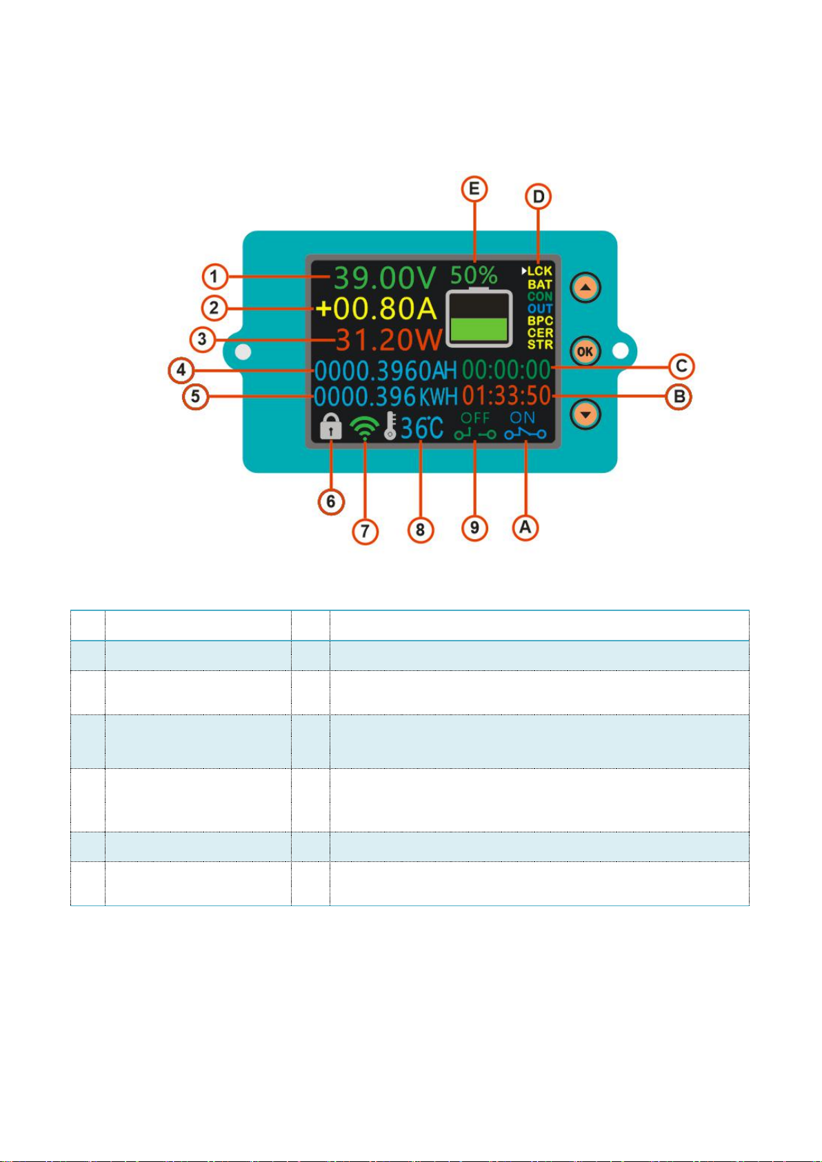
II.Description of interface of measuring board
1
Actual voltage value
8
Real-time measurement of temperature
2
Actual current value
9
Working state of charging relay
3
Actual functional rate
value
A
Working state of discharge relay
4
Cumulative AH
B
(OTP=0) Ordinary timer ,(OTP >0) Timing timer
5
Cumulative WH
C
Time required for battery filling or discharge (based on
charge/discharge current and capacity)
6
Press lock indication
D
Function Settings Options
7
Wireless communication
signal indication
E
Percentage of remaining capacity

5
III.Display Interface Description

6
IV. Wiring
(1) Self-supply wiring instructions (red positive, green negative)
Note: if the voltage range of the battery (power supply) under test is between (8-100
V), the jumper cap of the power supply selection interface can be adjusted to "2 W"
first. Connect the positive and negative electrodes of the battery (power supply) to the
voltage measurement port "+Bat-"; If the current direction of the current flowing
through the Hall sensor is the same as the direction of the arrow on the Hall sensor,
the measured current will show positive value, whereas the measured current will
show negative value, otherwise the measured current will show negative value

7
(2)External power supply wiring instructions (red positive, green
negative)
Note: if the voltage range of the battery (power supply) is not between (8-100 V),
the jumper cap of the power supply selection interface can be adjusted to "3 W" first.
Connect the positive and negative poles of the battery (power supply) to the negative
pole of the external power supply. Do not misconnect or reverse the positive and
negative electrodes of the battery (power supply). Connect the positive electrode of
the battery (power supply) to the negative electrode of the load through the Hall
sensor. When the current direction flowing through the Hall sensor is consistent with
the arrow direction on the Hall sensor, the measured current is positive and negative.

8
(3)Charges relay wiring instructions (red positive, green negative)
Note: the working power of the relay is provided by external power supply, if the
relay is connected, it should provide an external power supply with the same working
voltage as the relay. Connect the control port of the relay to the charging controller
interface, if you want to control the charging positive pole, pass the positive pole
through the relay, and if you want to control the charging negative pole, connect the
negative pole to the relay. When the relay is sucked, the “IN”lights are lit and
extinguished as a hint.

9
(4)Discharge relay wiring instructions (red positive, green negative)
Note: the working power of the relay is provided by external power supply, if the
relay is connected, it should provide an external power supply with the same working
voltage as the relay. Connect the control port of the relay to the interface of the
discharge controller. If you want to control the positive electrode of the discharge,
pass the positive wire through the relay, and if you want to control the negative
electrode of the discharge, connect the negative wire to the relay. When the relay is
sucked, the “OUT”lights are lit.

10
Chapter III Description of use
I. Wiring
Select the appropriate wiring method according to the range of the measured
voltage to ensure that the input voltage is within the range of the instrument. The
external power supply voltage is 8-60V, and the measured voltage exceeds 70V. It is
better to use independent power supply for the display screen to reduce the power
consumption of the motherboard.
Note: Self-supply detection voltage range :8V ~100V;
Test voltage range for external supply :0V ~120V;
II.Parameter Introduction and Setting
Parameter settings have a total of 4 pages, click the next key, you can enter the
next parameter or enter the next parameter settings page
(1)"LCK" key lock control, this function can lock the keys to prevent incorrect
operation to change the parameters, long press the up key to unlock;
(2)"BAT" set the total battery capacity value, which is used to calculate the
percentage of battery residual capacity, the specific parameter setting method
reference parameter setting method 1;
(3)"CON" the charging relay control option, move the cursor to this option, click
the OK button to control the charging relay on and off;
(4)"OUT" the discharge relay control option, move the cursor to this option, and
click the OK button to control the on-off of the discharge relay;
(5)" BPC" set the percentage of battery residual capacity, specific parameter setting
method reference parameter setting method two;
(6)"CER" the no-load current zero option, move the cursor to this option in the
no-load state, and click the OK button to zero the no-load current when the no-load
current value is not zero;
(7)"STR" the timing function control option, move the cursor to this option, and
click the OK button to start or pause the timing count;
(8)" TTL" the default discharge output relay status setting option, move the cursor to

11
this option, click the OK key to enter the settings interface, click the upper key or
lower key adjustment option, and then click the OK key to exit the settings page;
(9)"NCP" setting the protection option of charging overcurrent value, when the
external relay controls charging, when the charging current value is greater than the N
CP set value, the charging relay will disconnect and stop charging, and the buzzer will
alarm. Specific parameter setting method reference parameter setting method 1;
(10)"OCP" set the protection option of discharge overcurrent value, when the external
relay controls the discharge, when the discharge current value is greater than the OCP
set value, the discharge relay will disconnect and stop the discharge, and the buzzer
will alarm. Specific parameter setting method reference parameter setting method 1;
(11)" SFH" the communication channel search function, the display can not accept the
signal of the measurement module, enter this option, by adjusting the channel value,
search for the signal channel value, the channel is a matching successful channel
value;
(12)"FCH" the communication channel setting function to set the search SFH value to
the FCH, the next time the power on the default matching channel value;
(13)"OVP" set the protection option of charging overvoltage value, when the external
relay controls charging, when the charging current value is greater than the OVP set
value, the charging relay will automatically disconnect, stop charging and the buzzer
will alarm; and when the OVP value is not 0, the battery capacity will automatically
return to 100 when the battery voltage is greater than OVP;
(14)"LVP" set the protection option of discharge undervoltage value, when the
external relay controls the discharge, when the battery voltage value is less than the
LVP set value, the discharge relay will disconnect and stop the discharge, and the
buzzer will alarm. Specific parameter setting method reference parameter setting
method 1;
(15)"STV" setting the protection option of the voltage value of the discharge start
voltage, when the battery discharge relay is disconnected and the battery charging
voltage is higher than the voltage value set by the STV, the discharge relay is
automatically closed, and the specific parameter setting method refers to the

12
parameter setting method 1;
(16 )"BWH" set the total energy value of the battery, which corresponds to the
nominal WH number of the battery, the specific parameter setting method reference
parameter setting method 1;
(17)" DEL" setting the relay delay action time value, when the actual parameter value
exceeds the protection value, the relay will not start the protection function if it
returns to normal within the DEL set delay time, and the specific parameter setting
method refers to the parameter setting method 1;
(18)" STI" the option of setting the current value of the screen, after setting this
parameter, when the actual current value is less than the set current value for a period
of time, the LCD screen of the display will automatically extinguish, and when the
actual current value is greater than the set current value, the display screen will
automatically light up. Specific parameter setting method reference parameter setting
method 1;
(19)" TME" set the time value option of the fixed screen, after setting the parameter,
when the S TI value is 0, the time is started when no operation is done on the display,
and when the time value exceeds the set TME time value, the display will
automatically extinguish
When the STI value is less than 0, when the actual current value is less than STI, the
LCD screen automatically extinguishes when the timing time value is greater than the
TME value. When the actual current is greater than the set value, the LCD screen
automatically lights up;
"(20)" HUM" the LCD display color switching option, move the cursor to this option,
click the OK key to enter the settings interface, click the upper key or lower key to
adjust the option, and then click the OK key to exit the settings page, after restart into
the changed settings state;
(21)" LAG" the LCD display language option, move the cursor to this option, click
the OK key to enter the settings interface, click the upper key or lower key to adjust
the option, and then click the OK key to exit the settings page, and the display restarts
and enters the changed settings state;

13
(22)"OTP" setting the time value option for discharge, after starting the timing
function, the output state of the discharge relay will be switched when the timing time
value is greater than the OTP value, and then click STR to return to 0 to restart the
timing;
(23"RUN" curve mode waveform refresh start and stop control option, move the
cursor to this position, click OK key to start or pause waveform refresh;
(24)" CRU "; reservation non-functional
(25)" UYD" the curve shows the voltage magnification option, and when the voltage
value is too small to be displayed in the waveform table, the display effect of the
voltage waveform curve can be enhanced by adjusting the parameter value of the
option;
(26)" IYD" the curve shows the current magnification option. When the current value
is too small to be displayed in the waveform table, the display effect of the current
waveform curve can be enhanced by adjusting the parameter value of the option;
(27)"RSH" the curve refresh time adjustment option, by adjusting the parameter value
of the option can speed up or slow down the curve waveform refresh time;
(28)"SVE"; reserved non-functional
(29)"MOD" relay operating mode switching options, there are five relay working
modes; set five working modes to match different customer requirements;

14
Parameter setting method 1: here according to the setting B AT as an example, how to
set parameters;
1:first click on the upper key or lower key to move the cursor to the BAT position,
click on the OK key to enter the parameter setting page, as shown in the following
figure;
Project
Battery voltage
below LVP
discharge relay
disconnected
Battery
voltage
below LVP
charging
relay closed
Battery voltage
higher than
OVP charging
relay
disconnected
Battery
voltage
higher than
OVP
discharge
relay closed
Battery
voltage
higher than
STV
discharge
relay closed
Mode
0
Automatic
regulation
Manual
adjustment
Automatic
regulation
Manual
adjustment
No
Mode
1
Automatic
regulation
Manual
adjustment
Automatic
regulation
Automatic
regulation
No
Mode
2
Automatic
regulation
Automatic
regulation
Automatic
regulation
Manual
adjustment
No
Mode
3
Automatic
regulation
Automatic
regulation
Automatic
regulation
Automatic
regulation
No
Mode
4
Automatic
regulation
Automatic
regulation
Automatic
regulation
No
Automatic
regulation

15
2:click the lower key to switch the parameter adjustment bit, click the upper key
to change the parameter value, when the return value and the set value are the same as
the data sent successfully, click the OK key to exit the parameter save, At the same
time, the buzzer will send an alarm to indicate that the parameter is saved
successfully.
Parameter setting method 2: here according to the set communication channel value
FCH as an example, how to set parameters;
1:first click on the upper key or lower key to move the cursor to the FCH position,
click on the OK key to enter the parameter setting page, as shown in the following
figure;
2:click the lower key or the upper key to change the parameter value. When the
return value and the set value are the same as the data sent successfully, click the OK
key to exit the parameter save, and the buzzer of the measuring board will send out
the alarm sound to show that the parameter is saved successfully.

16
III. Display mode switching
The instrument has three display modes: full data mode, simple data mode,
voltage, current and temperature curve display mode. The method of display mode
switching: select the first item of cursor movement function, then click on the upper
key to switch the display mode, and the instrument will remember the set selection
mode.
Description: Green curve is voltage curve, red curve is current curve, The orange
curve is the temperature curve, The corresponding voltage range of the Y axis V,0-500
Current range 0-500A, Temperature range 0-100 degrees Celsius, When the measured
data is too small, For example, the current is only 0.8A so it is not obvious in the
curve, By adjusting the current curve magnification IYD to 50, Amplify the Y axis of
the current curve 50 times, So the current curve is more obvious. voltage curves can
be set UYD to achieve the same effect. Y axis coordinates have 270 points, The
longest refresh time is 90 seconds, By setting a curve to record a battery charge
discharge, Realize intuitive performance judgment.
Communication Protocol:
Baud rate: 9600
Send data format 0xFA +(FCH value)
Beginning value 0xFA( hexadecimal)
The address bit (FCH value) is converted to the corresponding hexadecimal number if

17
the FCH value is tested with the serial port assistant
If sent: 0xFA 0x40
Returns 27 data:
Data1= xFA0
Data2=FCH
DC current value: (Data3<<8|Data4)/1000
DC voltage value: Data5<<8|Data6
Cumulative energy value (WH):(Data7<<24| Data8||Data8<<16)/1000
Cumulative capacity value (AH):(Data11<<24| Data12||Data12<<16)/1000
Percentage of residual capacity: Data15/100;
Current direction: Data16(0:negative current ;1: positive current)
Charging relay working status: Data17
Discharge relay working status: Data18
Run cumulative
time :(Data19<<24|Data20Data19<<Data19<<16|Data20Data19<<Data19<<Data21D
ata19<<Data19<<8)(seconds)
Temperature: Data23
Output status value: Data24
Timing start-stop value: Data25
Empty: Data26
Empty: Data27

18
Attention and maintenance
1. can not exceed the instrument voltage and current range, otherwise it will damage
the instrument.
2. positive and negative electrodes can not be reversed, the reverse can not be
measured correctly.
3. operating temperature-10~50 ℃, storage temperature-20 and 70 ℃, and keep the
instrument in a dry environment.
4. do not try to disassemble this instrument, damage to the package will lead to
warranty failure. There are no parts that can be repaired by the user. The maintenance
can only be sent back to the factory through the designated maintenance network.
Do not move the instrument violently 5. the instrument works to avoid irreparable
damage to the internal circuit.
Table of contents