Blue Giant BLUE GENIUS SERIES Operating instructions
WARNING
DO NOT INSTALL, OPERATE OR SERVICE THIS PRODUCT UNLESS YOU HAVE READ AND
FULLY UNDERSTAND THE ENTIRE CONTENTS OF THIS MANUAL. FAILURE TO DO SO MAY
RESULT IN PROPERTY DAMAGE, BODILY INJURY OR DEATH.
INSTALLATION &
OWNER’S MANUAL
XDS3000 DOOR and DOCK GUARD with
TL85 VEHICLE RESTRAINT
and BLUE GENIUSTM CONTROLS BLUE GENIUSTM SERIES
XDS3000 and Blue GeniusTM. Issue Date: January 11, 2013. Rev.4 (Part#038-730E)

TABLE OF CONTENTS
1. ABOUT THE XDS3000 EXTRA DOCK SAFETY SYSTEM......................................................................................... 1
1.1 Owner’s Purchase Record...................................................................................................................................... 1
2. INTRODUCTION ......................................................................................................................................................... 2
2.1 Warranty Information............................................................................................................................................. 2
2.2 Exclusion of Liability.............................................................................................................................................. 2
2.3 Manufacturer's Note.............................................................................................................................................. 2
3. OPERATOR’S MANUAL SAFETY MESSAGE COLOR IDENTIFICATION................................................................ 3
3.1 Operational Safety Warnings................................................................................................................................ 3
4. LOCKOUT / TAGOUT PROCEDURE AND RULES..................................................................................................... 4
5. XDS DOCK AND TL85A INSTALLATION.................................................................................................................... 5
5. XDS DOCK AND TL85 INSTALLATION....................................................................................................................... 6
6. WELD INSTALLATION PICTORIAL............................................................................................................................. 7
7. INSTALLATION INSTRUCTIONS................................................................................................................................ 8
7.1 Installation Inspection............................................................................................................................................. 9
8. VEHICLE RESTRAINT INSTALLATION INSTRUCTIONS.......................................................................................... 10
9. ELECTRICAL AND HYDRAULIC INSTALLATION...................................................................................................... 11
9.1 TL85A and XDS .................................................................................................................................................... 11
9.2 TL85 and XDS ..................................................................................................................................................... 11
9.3 Final Inspection..................................................................................................................................................... 11
10. CONTROL STATION OPERATION.............................................................................................................................. 12
11. OPERATING INSTRUCTIONS..................................................................................................................................... 13
11.1 Functional Description......................................................................................................................................... 13
11.2 Stop Button Function........................................................................................................................................... 13
11.3 Deploying the Vehicle Restraint........................................................................................................................... 13
11.4 Operating Procedure (Method 1): Deploying the XDS Dock (Deck Button Only)................................................. 14
11.5 Operating Procedure (Method 2): Deploying the XDS Dock (Deck and Lip Buttons)......................................... 14
11.6 Operating Procedure: Returning Dock to Stored Position................................................................................... 15
11.7 Undeploying the Restraint Arm........................................................................................................................... 15
11.8 DDG- For End Loading / Unloading..................................................................................................................... 15
11.8.1 Lowered / Deactivated Position (Manually)...................................................................................................... 15
11.8.2 Deploying the Dock Leveler: Returning to Normal Lip-on-Load Bed Operation................................................ 16
11.8.3 DDG Bypass Mode.......................................................................................................................................... 16
11.9 DDG and Overheard Door Sensor...................................................................................................................... 17
11.10 Vehicle Restraint Override Feature.................................................................................................................... 17
12. EMERGENCY VEHICLE RESTRAINT LOWERING PROCEDURE............................................................................. 18
13. MAINTENANCE............................................................................................................................................................ 19
13.1 Planned Maintenance.......................................................................................................................................... 19
13.2 Operator Daily Inspection..................................................................................................................................... 19
13.3 Routine Servicing and Maintenance.................................................................................................................... 19
13.4 Planned Maintenance Intervals............................................................................................................................ 19
13.5 Maintenance Sequence........................................................................................................................................ 19
13.6 Recommended Hydraulic Fluids........................................................................................................................... 19
13.7 PM Checklist- Dock Equipment............................................................................................................................ 20
13.8 PM Checklist- Vehicle Restraint............................................................................................................................ 21
14. HYDRAULIC CYLINDERS............................................................................................................................................ 22
14.1 Hydraulic Deck Lifting Cylinder............................................................................................................................ 22
14.2 Hydraulic Lip Extension Cylinder......................................................................................................................... 22
15. VELOCITY FUSE- FALL SAFE.................................................................................................................................... 22
16. LEVELER HYDRAULIC HOSES.................................................................................................................................. 23
16.1 Deck Lifting Cylinder- Hose All Capacity............................................................................................................. 23
16.2 Lip Extension Cylinder-Hose All Capacity............................................................................................................ 23
17. SIDE SAFETY SKIRTS................................................................................................................................................. 24
18. XDS FLAP ACTUATOR- PARTS.................................................................................................................................. 25
24.2 Face Plates for Molded Rubber Bumpers........................................................................................................... 30
24.3 Laminated Bumpers............................................................................................................................................ 30

TABLE OF CONTENTS
19. XDS COMPLETE POWER PACK ASSEMBLY............................................................................................................. 26
20. PICTORIAL COMPONENT PARTS DRAWING............................................................................................................ 27
21. HYDRAULIC PARTS- DRAWING................................................................................................................................. 27
22. TL85 PARTS ILLUSTRATION...................................................................................................................................... 28
23. TL85A PARTS ILLUSTRATION.................................................................................................................................... 29
24. GENERAL PARTS ....................................................................................................................................................... 30
24.1 Molded Rubber Bumpers.................................................................................................................................... 30
24.2 Face Plates for Molded Rubber Bumpers........................................................................................................... 30
24.3 Laminated Bumpers............................................................................................................................................ 30
24.4 Face Plates for Laminated Bumpers................................................................................................................... 30
24.5 Flood Light.......................................................................................................................................................... 30
25. VEHICLE RESTRAINT TROUBLESHOOTING............................................................................................................ 31
26. DOCK LEVELER TROUBLESHOOTING..................................................................................................................... 32

1. ABOUT THE XDS3000 EXTRA DOCK SAFETY SYSTEM
Dealer:
Date in Service:
Number of Units:
Serial Number(s):
Door # :
OWNER’S PURCHASE RECORD
Please record information for future inquiries
The manufacturer offers a full line of dock levelers, dock safety equipment, accessories, ergonomic and scissor lift
equipment, and industrial trucks. Concurrent with a continuing product improvement program, specifications are subject
to change without notice. Please contact the manufacturer for latest information. Some features illustrated may be
optional in certain market areas.
The Blue Giant XDS3000 Extra Dock Safety System features our heavy-duty I-beam dock leveler with built-in door
and dock guard (DDG). A 4” (102 mm) maintained deck tilt prolongs deck life and prevents forklift damage. The raised
guard is designed to prevent forklift roll-off and protect overhead doors from impact damage.Toe guards, a maintenance
strut, and laminated bumpers provide extra safety to personnel and building during use. It includes the Blue Giant TL85
vehicle restraint, which applies 32,000lbs (14,545kgs) of restraining force behind its powerful mechanical locking
device. It safeguards against unscheduled departures, trailer creep and trailer walk, therefore increasing safety level at
the docks.
The Blue Genius™ Touch Control Panel with advanced smart performance technology controls the operation of both the
dock leveler and vehicle restraint, and alerts both the driver and dock attendants of safe/unsafe conditions. Its onboard
diagnostics and communications feature a user-friendly, LCD intelligent text display and keypad with supervisory
override.
1. 1 OWNER’S PURCHASE RECORD
XDS3000 with Blue Genius™ Controls
1

Loading Dock Equipment Manufacturers
A Product Section of Material Handling Industry of America,
A Division of Material Handling Industry
8720 Red Oak Blvd., Suite 201, Charlotte, NC, 28217-3992
Telephone: (704) 676-1190 Fax: (704) 676-1199
ALSO MEMBERS OF :
American National Standards Institute (ANSI)
1430 Broadway
New York, NY 10018
(212) 642-4900
LOADING DOCK EQUIPMENT MANUFACTURERS
2. INTRODUCTION
The following is a quick reference to important procedures that must be followed while using the XDS3000 System. It is
not intended to cover, or suggest that it does cover, all procedures necessary to ensure safe operation. All operators
should be aware of and abide by all workplace safety regulations applicable to the operation of the XDS3000 System.
These laws and regulations include but are not limited to:
• The Occupational Safety and Health Act (USA)
• Occupational Safety and Health Acts for Individual States (USA)
• Canadian Material Handling Regulations
For additional information on these regulations as well as industry standards that may apply to this product, please
contact:
The manufacturer assumes no liability for damage or injury to persons or property which occur as a result of defects or
faults in or incorrect use of XDS3000 System. The manufacturer also assumes no liability for lost profits, operating
downtimes, or similar indirect losses incurred by the purchaser. Injury to third parties, irrespective of its nature, is not
subject to compensation.
The manufacturer reserves the right to make changes at any time to the modules, components, and accessories,
concurrent with its continuing product development program. Specifications, operating instructions, and illustrations
included in this manual are subject to change without notice. Please contact manufacturer for the latest information.
MANUFACTURER’S NOTE
The XDS3000 has been carefully inspected and tested at the manufacturer’s plant prior to shipment, but should be
checked upon receipt for transport damage. Any observed transport damage is to be listed on the signed copy of the
freight document. Notify the freight forwarder of any damage WITHIN 48 HOURS.
2.2 EXCLUSION OF LIABILITY
2.3 MANUFACTURER’S NOTE
Thank you for purchasing Blue Giant products. We appreciate your business, and are confident that our product will
serve you for many years to come. In the event that you experience a problem with our product, our Warranty Center
is here to support the Blue Giant Product(s) that you have purchased.
To validate warranty on recently purchased equipment, please complete and submit your information with our on-line
Warranty Registration at www.BlueGiant.com.
For more information about Blue Giant's Warranty Support, please contact your local Blue Giant Equipment dealer,
representative or authorized partner near you. You may also visit www.BlueGiant.com or phone 1-905-457-3900.
* Note that failure to validate warranty at the time of receipt can seriously affect the outcome of any claim.
2.1 WARRANTY INFORMATION
XDS3000 with Blue Genius™ Controls
2
3.1 OPERATIONAL SAFETY WARNINGS
3. OPERATOR’S MANUAL SAFETY MESSAGE COLOR IDENTIFICATION
This manual includes color-coded safety messages that clarify instructions and specify areas where potential hazard
exists. To prevent the possibility of equipment damage and serious injury or death, please observe strictly the
instructions and warnings contained in the messages. If warning decals become damaged or missing, replace them
immediately. Avoid accidents by recognizing dangerous procedures or situations before they occur.
Serious injury or death will likely occur if the instructions are
not followed. Procedures marked IMPORTANT must be followed in order to
prevent damage to machinery.
Serious injury or death may occur if the instructions are not
followed. Instructions marked CAUTION concern safe operating
procedure. Failure to comply may result in personal injury.
• DO NOT operate leveler with anyone standing in its path of operation.
• DO NOT service leveler unless Maintenance Stand is properly engaged.
• BEFORE BEGINNING ANY SERVICE PROCEDURES:
– Position the dock leveler in the vertically stored position.
– Disconnect the power and follow all LOCKOUT / TAGOUT procedures.
• DO NOT operate leveler without filling the cylinder if the leveler has not been in service for an extended period of time.
• Procedure for filling cylinder:
– Press and hold the ‘Deck’ button (Run Pump). Operate for (35) seconds.
• Keep away from hinge when operating leveler.
• Post safety warnings and barricade working area at dock level and
at ground level to prevent unauthorized use of the leveler during
maintenance/service.
•During installation, anchors must be properly torqued to obtain the
necessary anchoring strength. DO NOT USE IMPACT DRIVERS.
• DO NOT drive or walk onto the transport vehicle until it is parked
against the dock bumpers and the wheels are chocked, or the
Vehicle Restraint has been fully engaged and the lights have
changed to GREEN inside and RED outside.
• NEVER attempt to lift or hold the lip out by hand. Serious personal
injury could occur.
• DO NOT remove lifting equipment until:
a) The main cylinder has been filled.
b) The Maintenance Stand has been installed and engaged.
• ALWAYS check the rigging to make sure that it is secure before
proceeding to lift the unit. Never stand under any unit being
lifted.
• NEVER remove the wheel chocks until loading/ unloading is finished
and the truck driver has been given permission to depart, or the
Vehicle Restraint has been released and the lights have changed
to RED inside and GREEN outside.
• DO NOT ground welding equipment to any hydraulic cylinder or
electrical components.
• DO NOT attach welder as ground to leveler platform when welding on
base frame assembly. Attach welder ground to base frame
assembly only. Otherwise damage to bearings or hydraulic
equipment will occur.
• DO NOT allow the drill to go too deeply when drilling holes in the
control box. Damage to the control systems may occur.
• NEVER use air to blow debris from control box. Use a vacuum to
remove debris from control box.
• DO NOT connect green ground lead into control box or junction box
until all welding has been completed.
• CHECK HYDRAULIC FLUID LEVEL. Deck mounted power unit
has been filled with fluid but cylinders, hoses and manifold are
shipped dry.
•NOTE - check motor rotation. Jog the motor until rotation has been
determined. DO NOT allow the motor to run in reverse for more
than a couple of seconds, otherwise the power unit may become
damaged.
• DO NOT force valve adjustment screws against internal stops.
Damage will occur to the valve/seat.
•If a procedure is not clearly defined in this manual, contact your
authorized Service Representative.
• ONLY TRAINED PERSONNEL should operate or service this equipment.
• DO NOT operate leveler until freight carrier is parked against the dock bumpers and has been secured.
• ALWAYS return the leveler platform to the proper stored position.
• ALWAYS conduct routine inspections and maintenance. Failure to conduct could cause personal injury or damage to equipment.
XDS3000 with Blue Genius™ Controls
3

4. LOCKOUT / TAGOUT PROCEDURE and RULES
XXXXXXXXXXXX
XXXXXXXXXXX
OPERATE
DO NOT
ABOVE: APPROVED WAY TO LOCKOUT / TAGOUT
In accordance with the rules and regulations of the
Occupational Safety and Health Administration (OSHA),
all affected employees must be notified that the machine
or equipment will be shut down and locked out to perform
repair or maintenance work. The work area must be
checked to ensure that all personnel have been removed
or safely repositioned. The machine or equipment power
supply shall be locked in the OFF position or
disconnected from the energy source. Blue Giant®
strongly recommends that only OSHA-approved lockout
devices be utilized.
The energy isolating device must bear a prominent
warning tag indicating that work is being done on the
equipment and the name of the authorized employee
responsible for the lockout. It is mandatory that tagout
devices not be susceptible to deterioration or illegibility
due to weather conditions or exposure to chemicals and
moisture.
Always lockout and tagout any power source before
performing any work on any electrical devices or
electrical controls according to OSHA regulations
and approved local electrical codes.
!
XDS3000 with Blue Genius™ Controls
4

4”
20”
14”
X
UNDER DOCK
HYDRAULIC VEHICLE RESTRAINT
CONCRETE PAD
RESTRAINTS
REMOTE POWER
PACK
NOTE: DOCK FACE & DRIVEWAY TO BE CONSTRUCTED OF
CONCRETE AND IN GOOD CONDITION, CONSULT
MANUFACTURE IF OTHER CONDITIONS EXIST.
CAST-IN-PLACE MOUNTING
PLATE (OPTIONAL)
NOTE: FUSED DISCONNECT
BY OTHERS
BLUE GENIUS
CONTROL BOX
(MOUNTED & WIRED
BY OTHERS)
TRAFFIC LIGHTS
(MOUNTED & WIRED BY OTHERS)
66”
84”
MAIN POWER
(TO CONTROL STATION)
MOTOR POWER FEED
RUN ONE 1-1/2” I.D. CONDUIT
FOR THE 1 HOSE
COMMUNICATION CABLE FROM
THE REMOTE POWER PACK &
NETWORK JUNCTION BOX TO
THE RESTRAINT AS SHOWN.
8”
TL85 POWER PACK
!
CAUTION
MOV E O N
GREEN ONLY
!
CAUTION
MOV E O N
GREEN ONLY
123
456
789
#0*
EnterOn Green
ProceedWithCaution
DoNot Enter
Release
Engage
SEL
ESC
>
>
1 2 3
6
5
4
789
*
0
#
Restraint
Disconnectpower
CAUTION
!
beforeopeningpan el
.
66”
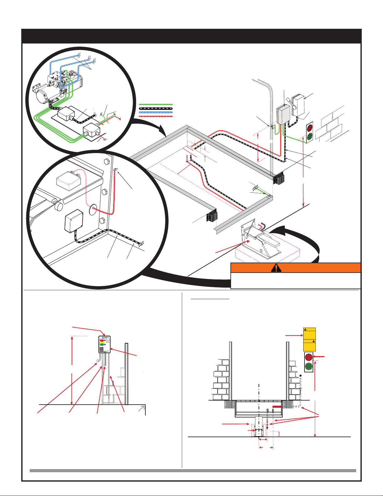
ELECTRICAL REQUIREMENTS:
• MOUNT CONTROL BOX STATION TO WALL, SIGNAL LIGHTS AND DRIVER WARNING SIGNS
• FUSED DISCONNECT PROVIDED BY OTHERS AND WIRING BY OTHERS
• INSTALL CABLE FROM CONTROL BOX STATION TO POWER PACK (BY OTHERS)
• INSTALL CABLE FROM CONTROL BOX STATION TO POWER SUPPLY (BY OTHERS)
GROUND LEVEL
1-1/2” DIA. CONDUIT FOR 1
HOSE COMMUNICATION
CABLE
HYDRAULIC VEHICLE RESTRAINT
CAST-IN-PLACE MOUNTING
PLATE (OPTIONAL)
CONTROL STATION
(MOUNTED ON
DRIVERS SIDE)
INSTALLATION DETAILS:
FOR RESTRAINT, KEEP BASE PLATE 90 DEGREES TO THE DOCK FACE AND PROVIDE POSITIVE SUPPORT
BETWEEN THE DRIVEWAY AND THE UNDERSIDE OF THE RESTRAINT. SUFFICIENT SHIMS MUST BE
POSITION AND WELDED SECURELY IN PLACE. WITH THE RESTRAINT POSITIONED, USE THE BACK PLATE
AS A TEMPLATE AND DRILL SIX (6) HOLES 3/4” DIA. X 6.5” DEEP FOR ANCHORS.
FLOOR ANCHORING IS OPTIONAL TO DOCK FACE MOUNTING.
RESTRAINT EXTENSION PLATE REQUIRED FOR PROJECTED PIT APPLICATION (OPTIONAL ACCESSORIES).
MAIN POWER
FEED CABLE
(from fused
disconnect)
TRAFFIC LIGHT
CABLE
(to the outside)
POWER CABLE
(Dock Leveler)
TL85 HYDRAULIC HOSES &
COMMUNICATION CABLE
(to the outside)
8”
12”
84”
IF INSTALLING A COMBO DOCK /
RESTRAINT. RUN TWO 1/2”
CONDUITS. ONE FOR THE
COMMUNICATION CABLE AND
ONE FOR THE POWER WIRING TO
THE POWER PACK.
NEW CONSTRUCTION (COMBO DOCK C/W POWER PACK & RESTRAINT):
CONDUIT MADE OF RIGID PLASTIC 80 P.S.I. 8” MIN.BEND RADIUS.
MINIMUM CONCRETE STRENGTH 3,000 P.S.I.
HYDRAULIC HOSE LINES
POWER WIRING
CABLES
COMMUNICATION CABLES
DO NOT RUN MAIN POWER
WIRING THROUGH TOP OF
CONTROL STATION
NOTE: ALL CONDUIT
ENTRY INTO CONTROL
PANELFROM BOTTOM.
ARRANGE WIRING TOAVOID
HIGH & LOW VOLTAGE
CROSSING OVER INSIDE
CONTROL BOX.
TRAFFIC LIGHTS
(MOUNTED DRIVERS SIDE)
PART #032-461
DRIVER WARNING SIGN
(MOUNTED DRIVERS SIDE)
PART #038-225
5. XDS DOCK (pit mounted) and TL85A (wall mounted) COMBO INSTALLATION
STOP
Deck
Leveler
LIP PROXIMITY SENSOR
!
!!
DO NOT WIRE HIGH AND LOW VOLTAGES IN THE SAME CONDUIT. High
voltage range is 115V and up. Lower voltages include the communication and
solenoid wiring as well as the I/O.
REMOTE
I/O BOX
DOCK
HYDRAULICS
LIP PROXIMITY SENSOR
COMMUNICATION
CABLE
(to control box)
TO DDG SENSOR
DOCK MOTOR
JUNCTION BOX
TO CONTROL BOX
NOTE: *FRONT VI EW SHOWS THE TL85A VEHICLE RESTRAINT IN ITS ENGAGED/RAISED POSITION. *DRAWINGS NOT TO SCALE
FRONT ELEVATION VIEW*INSIDE BUILDING VIEW*
RESTRAINT MOTOR JUNCTION BOX
RESTRAINT
J-BOX
DOCK CABLE
(To Remote
I/O BOX )
COMMUNICATION
CABLE
(to the pit)
1. DRILL ONE HOLE THROUGH THE WALLTO THE OUTSIDE AND WIRE THE L.E.D
TRAFFIC LIGHTS.
2. INSTALL ONE 1/2” I.D. CONDUIT FROM THE CONTROL BOX TO THE REMOTE I/O
FOR THE DOCK’S COMMUNICATION CABLE.
3. INSTALL ONE 1/2” I.D. CONDUIT FROM THE CONTROLBOX TO THE DOCK’S POWER
PACK FOR MOTOR WIRING.
4. INSTALL 1-1/2“ I.D. CONDUIT FROM THE RESTRAINT POWER PACK TO THE DOCK FACE
FOR THE RESTRAINT’S HYDRAULIC HOSE.
5. INSTALL 1/2” CONDUIT FROM THE PIT TO DOCK FACE FOR THE CONTROL CABLE.
XDS3000 with Blue Genius™ Controls
5
6. XDS3000 with TL85 (self-contained)
HYDRAULIC
VEHICLE
RESTRAINT
LIP
PROXIMITY
SENSOR
AD
NOTE: FUSED DISCONNECT
BY OTHERS
BLUE GENIUS
CONTROL BOX
(MOUNTED & WIRED
BY OTHERS)
TRAFFIC LIGHTS
(MOUNTED & WIRED
BY OTHERS)
66"
MAIN POWER
(to control station)
MOTOR WIRING FOR
DOCK
!
CAUTION
MOVE ON
GREEN ONLY
!
CAUTION
MOVE ON
GREEN ONLY
ELECTRICAL REQUIREMENTS-
• MOUNT CONTROL BOX STATION TO WALL, SIGNAL LIGHTS AND DRIVER WARNING SIGNS
• FUSED DISCONNECT PROVIDED BY OTHERS AND WIRING BY OTHERS
• INSTALL CABLE FROM CONTROL BOX STATION TO POWER PACK (BY OTHERS)
• INSTALL CABLE FROM CONTROL BOX STATION TO POWER SUPPLY (BY OTHERS)
GROUND LEVEL
1/2" DIA. CONDUIT FOR
COMMUNICATION CABLE
HYDRAULIC VEHICLE RESTRAINT
CAST-IN-PLACE
MOUNTING
PLATE (OPTIONAL)
TRAFFIC LIGHTS
(MOUNTED DRIVERS SIDE)
PART #032-461
DRIVER WARNING SIGN
(MOUNTED DRIVERS
SIDE ABOVE LIGHT)
INSTALLATION DETAILS:
FOR RESTRAINT, KEEP BASE PLATE 90 DEGREES TO THE DOCK FACE AND PROVIDE POSITIVE SUPPORT
BETWEEN THE DRIVEWAY AND THE UNDERSIDE OF THE RESTRAINT. SUFFICIENT SHIMS MUST BE
POSITION AND WELDED SECURELY IN PLACE. WITH THE RESTRAINT POSITIONED, USE THE BACK PLATE
AS A TEMPLATE AND DRILL SIX (6) HOLES 3/4” DIA. X 6.5” DEEP FOR ANCHORS.
FLOOR ANCHORING IS OPTIONAL TO DOCK FACE MOUNTING.
RESTRAINT EXTENSION PLATE REQUIRED FOR PROJECTED PIT APPLICATION (OPTIONAL ACCESSORIES).
8"
12"
15"
84"
MINIMUM CONCRETE STRENGTH 3,000 P.S.I.
POWER WIRING
COMMUNICATION CABLES
HYDRAULIC HOSE LINES
CABLE
20"
12"
14"
4"
NOTE: WHEN INSTALLING
THE CONDUIT FOR THE HOSE
LINES AND WIRES TO CONSIDER THE
BENDING RADIUS OF THE CONDUITS. TOO
MUCH OF A BEND WILL MAKE IT DIFFICULT OR
IMPOSSIBLE TO RUN THE HOSES THROUGH AND
POSSIBLY DAMAGE THE CONDUIT ITSELF.
UNDER DOCK
1. Run motor wiring from the control panel to the pit motor box for the
dock and restraint.
2. Run the communication cable from the control panel through the pit
to the restraint. DO NOT run it through the same conduit as the motor
wiring.
3. Run motor wiring from the pit motor box to the restraint.
4. Run control cable from the restraint to the pit junction box.
5. After hole has been drilled in appropriate location on the wall, wire the
LED traffic lights.
NEW CONSTRUCTION (COMBO DOCK & RESTRAINT):
CONTROL STATION
(MOUNTED ON
DRIVERS SIDE)
DO NOT RUN MAIN POWER WIRING THROUGH TOP OR OR SIDE
OF CONTROL STATION
NOTE: ALL CONDUIT
ENTRY INTO CONTROL
PANELFROM BOTTOM.
ARRANGE WIRING TO
AVOID HIGH & LOW
VOLTAGE CROSSING
OVER INSIDE CONTROL
BOX.
MAIN POWER
FEED CABLE
(from fused
disconnect)
TRAFFIC LIGHT
CABLE
(to the outside)
RESTRAINTS
MOTOR WIRING
(to the outside)
COMMUNICATION
CABLE
(to the outside)
DO NOT WIRE HIGH AND LOW VOLTAGES IN THE SAME CONDUIT. High
voltage range is 115V and up. Lower voltages include the communication and
solenoid wiring as well as the I/O.
SEL
ESC
estraint
>
>
R
123
456
789
#0*
EnterOn Green
ProceedWithCaution
DoNot Enter
Release
Engage
1 2 3
6
5
4
789
*
0
#
Disconnectpower
CAUTION
!
beforeopeningpan el
.
STOP
FRONT ELEVATION VIEW*INSIDE BUILDING VIEW*
NOTE: *FRONT VIEW SHOWS THE VEHICLE RESTRAINT IN ITS ENGAGED/RAISED POSITION. *DRAWINGS NOT TO SCALE
MOTOR WIRING FOR
RESTRAINT
OVERHEAD DOOR
INTERLOCK
(OPTIONAL)
MOTOR WIRING
TO I/O BOX
MOTOR WIRING MUST HAVE ITS
OWN CONDUIT SEPARATE FROM
THE COMMUNICATION CABLE
MOTOR
WIRING
REMOTE
I/O BOX
REMOTE
I/O BOX
DOCK
HYDRAULICS
LIP PROXIMITY
SENSOR
TO DDG
SENSOR
DOCK
MOTOR
J-BOX
TO CONTROL
BOX
COMMUNICATION
CABLE
(to control box)
TO VEHICLE RESTRAINT
JUNCTION BOX
(atypical)
(atypical)
(atypical)
66"
(atypical)
84"
XDS3000 with Blue Genius™ Controls
6
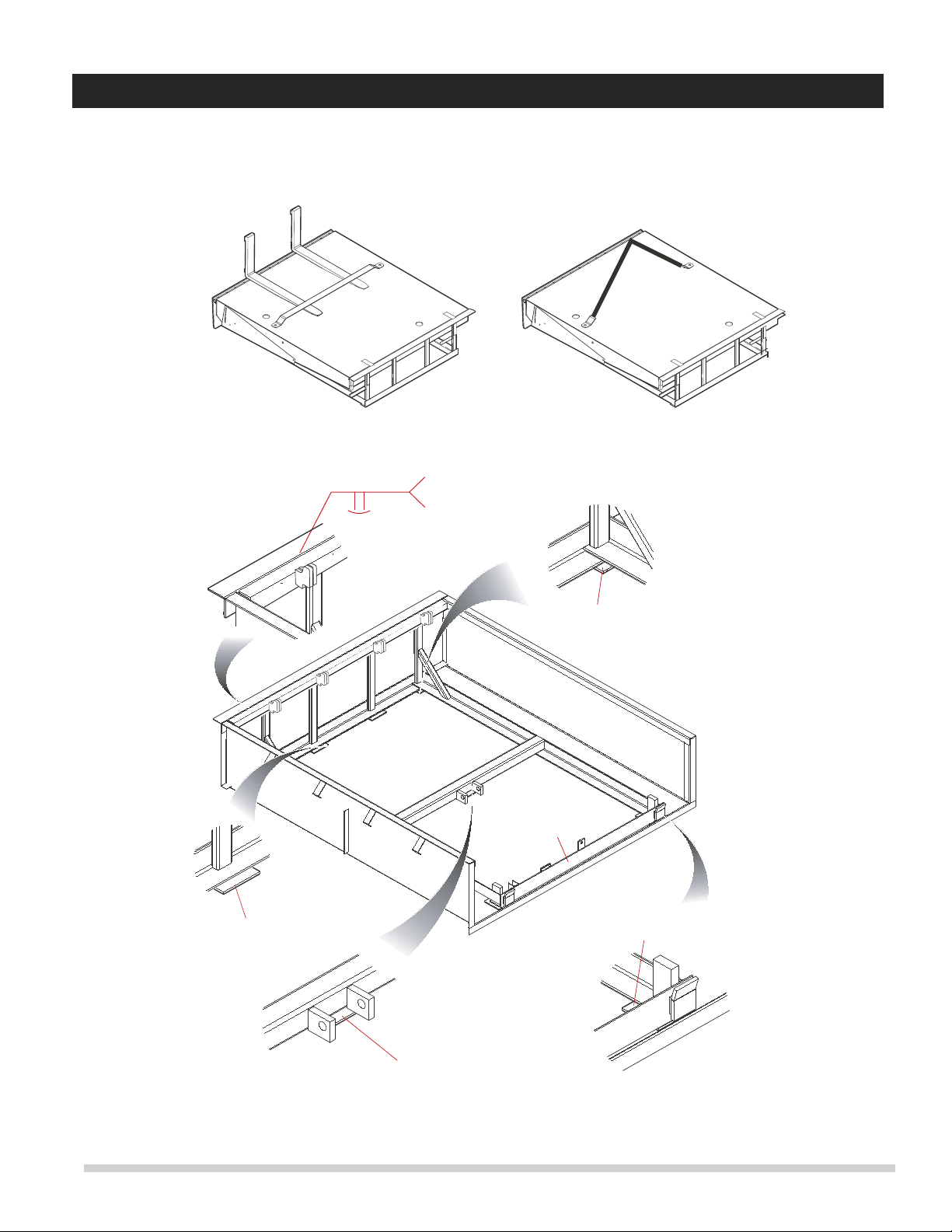
DOCK LEVELER
BASE FRAME
SHIM LIFT ARM
BASE BRACKET
5" X 5" - 127mm x 127 mm
STITCH WELD
1/4"6”
SHIM BOTH SIDES
5" X5" - 127mm x 127 mm
SHIM BOTH SIDES
5" X5" - 127mm x 127 mm
SHIM 4" x 4"
(102mm x 102mm)
FORK LIFT TRUCK HANDLING SLING HANDLING
HYDRAULIC
6. WELD INSTALLATION PICTORIAL
WELD INSTALLATION PICTORIAL
(Shim placement guidance only- dock depicted may not be same model covered in this manual)
XDS3000 with Blue Genius™ Controls
7

7. DOCK LEVELER INSTALLATION INSTRUCTIONS
D
PIT MUST BE
KEPT SQUARE
C
DOCK BUMPERS
Typically 19-1/2” or
23-1/2” (495 or 595mm).
Typically 19” or
23”(485 or 585mm)
Figure 1 : Pit Layout - Typical
!
IMPORTANT
!
IMPORTANT
!
Do not install, operate and/or service this leveler until you
have read and understood all of the safety information
and instructions contained herein and on the leveler.
Do not work under or around leveler being installed
without first placing adequate barriers to positively
prevent vehicle traffic from entering the work area.
Keep hands and feet clear of dock leveler pinch points.
!
!
The information below is crucial to proper installation:
Pit Curb Angles
A. Must be level side-to-side and front-to-back.
B. Must be square at both rear corners.
C. Side curb angles must be parallel to each other.
D. Finished floor to be flush with top surface of curb angle.
The leveler must be welded to a firmly embedded steel or other
dock steel as described in the installation instructions.
Do not attempt to use only bolts or anchors, to attach the dock
leveler to the concrete.
1. Prior to installation, clean pit thoroughly and verify that all
dimensions are in accordance with manufacturer
specifications.
2. Measure height of rear corners of dock leveler, bottom of
frame to top of deck plate, typically 19” or 23”(485 or
585mm). Measure depth of pit at both rear corners where
rear bottom corners of frame will be positioned. Locate and
place suitable shims (not supplied) in pit corners to produce a
depth to match frame height.
3. Measure height of dock leveler front corners, bottom of frame
to top of deck plate, typically 19-1/2” or 23-1/2” (495 or
595mm). Measure depth of pit at both front corners where
front bottom corners of frame will be positioned. Locate and
place suitable shims (not supplied) at both front corners to
produce a depth to match frame height. See Figure 1.
!
!
All electrical work must be performed by trained and authorized
personnel.
4. Prepare to hook up electrical wires and hydraulic hoses if
required. Identify hose ends as “Lip” and “Deck”. For units
with self-contained (mounted under deck) power pack,
establish a temporary electrical hook-up to enable deck to be
raised and lowered during installation. For units with a wall
mounted (remote) power pack, prepare hydraulic hoses for
“pulling” through conduit and electrical wires for temporary
hook up.
Use caution when lifting or moving the leveler. Do not attempt
to lift without suitable hoisting equipment capable of lifting as
much as 3500 lbs. Do not work beneath a raised object. Follow
all hoisting safety requirements.
5. Using extreme caution, sling dock leveler into place squarely
above pit and lower gently onto pre-located shims. Locate
and square dock leveler to best suit pit and dock face. Space
between sides of deck and sides of pit should be equal. Line
up the bottom clevis holes to the pivot edges of the rear
It is important that the shims fill the space between the
bottom edge of the back beam and face of the curb angle, as
well as behind each hinge lug on the top edge. Confirm that
the top of the back beam is flush with the top surface of the
rear curb angle, and then finish weld back beam to curb
angle.
6. If the rear beam does not line up squarely with the rear curb
angle, use 3” x 6” (75mm x 150mm) shims of suitable
thickness to fully support top rear and bottom rear of rear
beam at weld areas. Weld rear beam to curb steel with 1/4”
x 6” (6mm x 150mm) welds, on 9-5/8” (250mm) centers.
7. Remove sling brackets, chains, etc. from the deck. Remove
and discard the shipping bolts from the front of the dock
leveler lip plate and the rear tilt bar.
8. Check the deck height to confirm that it is flush with the top
of the side curb angles and tack-weld all front shims to the
front curb angle and front frame.
9. Install the lip sensor and interlock sensor. Adjust the proximity
switches by loosening the holding nuts and setting the gap.
Once the desired adjustment has been achieved, re-tighten
the holding nuts.
XDS3000 with Blue Genius™ Controls
8
10. Mount Blue Genius Control Station assembly in a suitable
location. Mount power unit in a suitable location if
applicable (remote power pack).
11. If power unit is mounted remote from pit (wall mounted)
permanently attach hydraulic hoses. “Lip” hose is
attached to the top fitting on the power unit manifold block
and the “Lift” hose is attached to the side fitting.
12. Perform a temporary electrical hook-up to allow use of
power unit to raise dock leveler. Confirm correct motor
rotation on start-up of 3 phase units – if motor runs but
deck will not raise, qualified personnel to interchange any
two motor leads.
13. Touch and hold “Deck” button to raise deck and extend lip.
Raise and position maintenance strut. Release “Up” button
and allow dock leveler to lower onto maintenance strut.
Install additional blocking to assure deck can not lower
unexpectedly and place traffic barriers as required.
!
Do not work beneath the dock leveler without engaging the
maintenance strut.
Do not work beneath the dock leveler without following
proper lockout procedures. Disconnect and lockout the
electrical power supply, and confirm that there is no power
to the dock leveler control panel. Also confirm that it cannot
be turned on again accidentally.
.
1. Clean up the entire work area and apply touch-up paint to all
welds, scratches and burns.
2. Ensure that all concrete wedge anchors have been
securely tightened.
3. Test operate the unit through several full cycles of operation.
Refer to the Operating Procedures section. If problems are
noted, consult the TROUBLESHOOTING section of this
manual.
4. Leave these Instructions with the Dock Leveler for use by
owner.
7.1 Installation Inspection
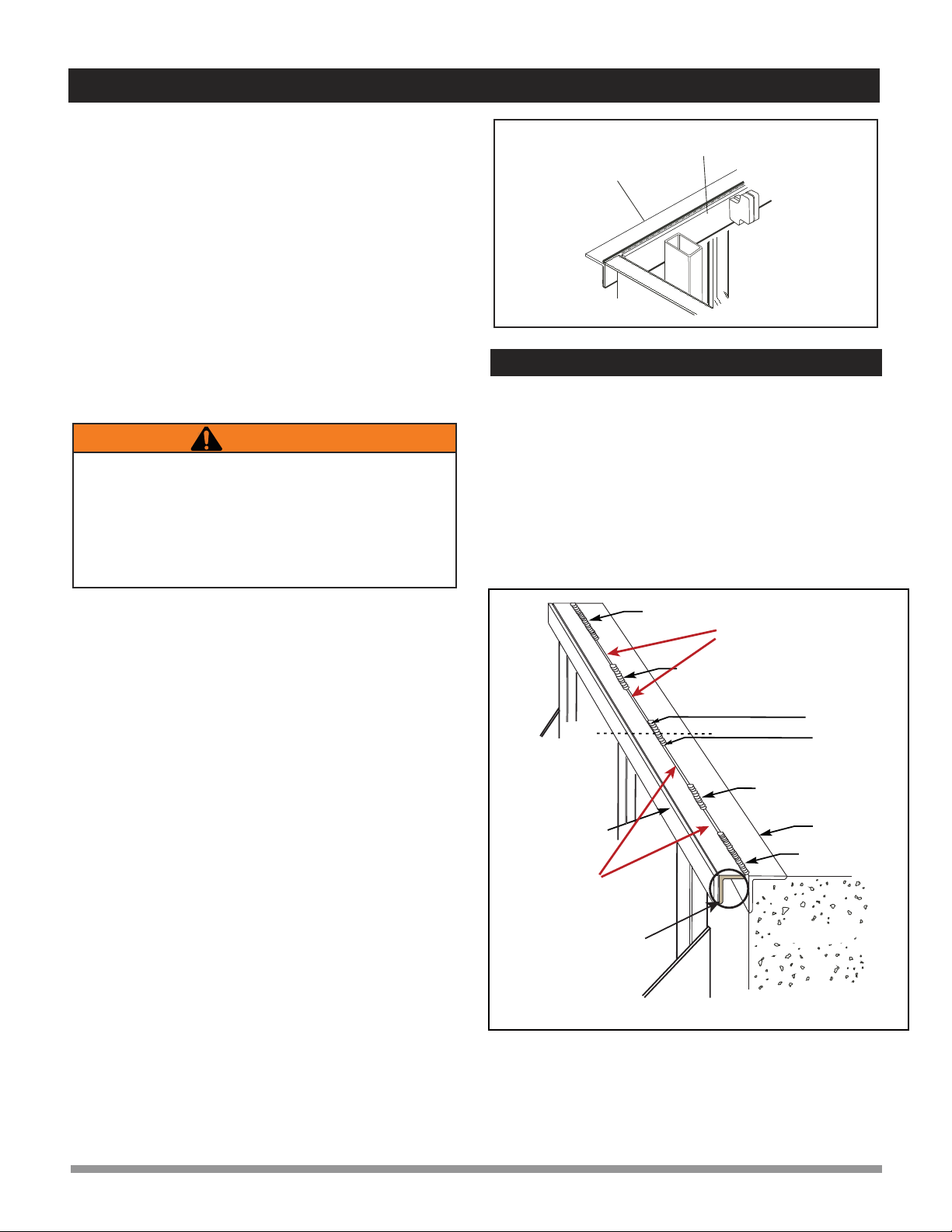
7. DOCK LEVELER INSTALLATION INSTRUCTIONS
UPPER REAR
PIT ANGLE
REAR FRAME
BAR
14. Remove the pin from telescopic maintenance strut, and
extend the maintenance strut to the desired height. Then
reinsert pin and walk the deck down to engage the strut.
15. Rear frame on most models has one or more vertical frame
members in addition to rear corner vertical members.
Place adequate shims directly under each vertical member
to fill space between bottom frame and floor of pit. Finish
weld all rear shims.
16. Measure thickness of shims that were installed under
middle of front frame and place same thickness of 6” x 6”
(150mm x 150mm) shims under base of deck cylinder.
Finish weld to cylinder mounting plate.
17. Finish weld all shims securely to the front curb angle and
front frame.
18. Install specified dock bumpers as required. Do not use the
dock leveler to be used without bumpers, as damage to
both building and leveler may result.
19. Release bottom safety skirts by removing and discarding
shipping bolts, one bolt from each side.
20. Make permanent electrical and hydraulic connections as
required.
21. Mount “Operating Hazards DANGER” placard, provided
with these Instructions to the wall in plain view of dock
leveler operations.
22. Perform a final inspection and determine that all work is
completed properly. Clean pit and work area
thoroughly and apply touch-up paint to weld burn areas,
scratches, etc.
23. Test operate the unit through several full cycles of all
functions. If adjustments are necessary, refer to the
TROUBLESHOOTING section of this manual.
1/2” X 8” (13mm x 203mm) WELD
BACK OF DECK
FRAME
CONCRETE PIT
1/2” X 6” (13mm x 152mm) WELD
CENTER
LINE
REAR PIT ANGLE
CAST-IN
REAR FILLER
(OPTIONAL- AS
REQUIRED BY
PIT LENGTH)
1/2” X 6” (13mm x 152mm) WELD
1/2” X 6” (13mm x 152mm) WELD
1/2” X 8”
(13mm x 203mm) WELD
ENSURE THAT EQUAL SPACING EXISTS
BETWEEN WELDS
ENSURE THAT EQUAL SPACING EXISTS
BETWEEN WELDS
FIGURE 2
XDS3000 with Blue Genius™ Controls
9
8. VEHICLE RESTRAINT INSTALLATION INSTRUCTIONS
1. Clean all dirt and debris from the driveway and dock face where
the vehicle restraint is to be installed.
2. To ensure maximum strength, the vehicle restraint should be
installed on a poured concrete dock face or concrete pad. For
cement block construction or a dock face with poor quality
concrete, obtain custom lag plates and/or lag anchors from the
manufacturer. If an asphalt driveway is broken, cracked, or
otherwise damaged (i.e. missing pieces), a 6” deep concrete
pad should be poured as a replacement.
3. Using suitable hoisting equipment, position the vehicle restraint
square against the dock face, and centered with the door
frame.
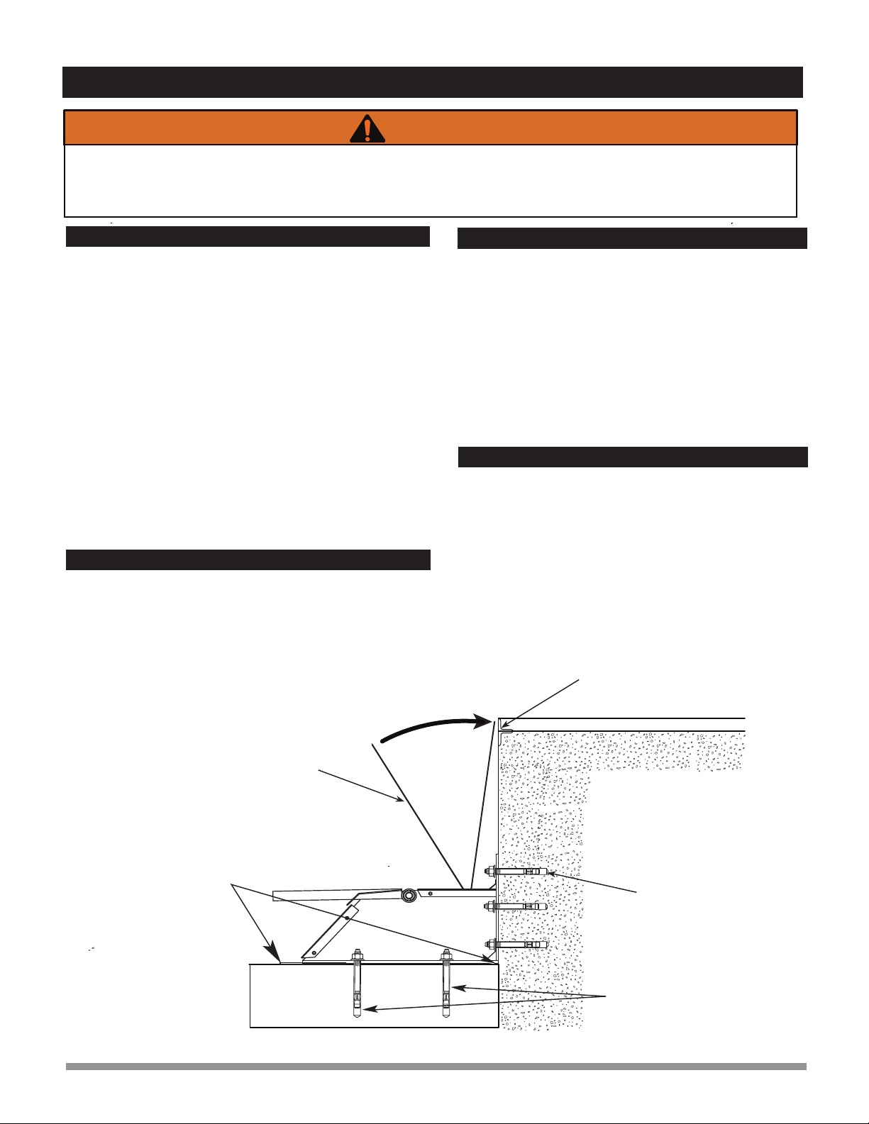
4. Keep the vehicle restraint base plate at a 90 degree angle to the
dock face and place a sufficient thickness of shims (not
supplied) between the driveway surface and the base plate’s
outer edge. Shims must be a minimum 13” x 6” in size and be
permanently welded together and to the base-plate.
1. With the vehicle restraint properly positioned and using back
plates as a template, drill six holes 5/8” in diameter and 6” deep
in the dock face concrete. Clean out holes and install anchors
and lag bolts (supplied with the restraint) with a torque of
110ft/lbs (149Nm). Optional anchoring to concrete pad rather
than wall plate.
Also refer to Section 9: Electrical and Hydraulic
Installation.
1. For the remote power pack (for the TL85A model only),
securely mount the hydraulic power pack horizontally on an
interior wall adjacent to the doorway opening, at
approximately 8 feet (2438 mm) above floor level, or
securely under the dock.
2. Securely mount the exterior traffic lights and signs on the
exterior wall adjacent to the doorway at approximately 84”
above the driveway.
1. Permanently mount the sensor wand onto the sensor switch
with the set screws provided. When at rest, the wand must
be in the forward position. Tighten fasteners securely.
2. Rotate the wand (move backward) to make contact with the
dock face. Contact point must not be above the top edge of
the pit opening and floor If the contact point is higher, modify
the wand.
Do not install, operate, or service the TL85AVehicle Restraint unless trained and authorized to do so. Read all safety information and
instructions in this manual.
When restraint is being installed, place adequate barriers to prevent vehicle traffic from entering the work area.
Follow proper lockout / tagout procedures.
SHIMS (13” X 6”)
THICKNESS AS REQUIRED 5/8” x 6” Concrete
Anchor Bolts
Recommended Torque:
110 ft-lb (149 Nm)
CONCRETE
DOCK FACE
TOP EDGE OF
PIT OPENING / FLOOR
WAND
ABOVE: WHEN INSTALLING THE RESTRAINT MOUNT TO A CONCRETE DOCK FACE AS SHOWN.
8.1 Install Preparations
8.2 Install Mounting
8.3 Electrical and Hydraulic Installation
8.4 Final Inspection and Setup
Optional
Floor Mount Anchor Bolts
in Concrete Pad (See Step
8.2)
XDS3000 with Blue Genius™ Controls
10
9. ELECTRICAL AND HYDRAULIC INSTALLATION
1. Securely mount the exterior traffic lights and signs on the
exterior wall adjacent to the doorway (on the driver’s side), at
approximately 8 feet (2438mm) above floor level.
2. Drill one hole through the wall to the outside and run a conduit
for the L.E.D. traffic lights.
3. Install one 1/2” I.D. conduit from the control box to the remote
I/O box for the dock’s signal cable.
4. Install one 1/2” I.D. conduit from the control box to the dock’s
power pack for the motor wiring.
5. Install one 1 1/2” conduit from the restraint power pack to the
dock face for the restraint’s hydraulic hose.
6. Install 1/2” I.D. conduit from the pit to the dock face for the
control cable.
7. Complete the electrical hookup between the exterior traffic
lights and control panel.
1. Check all hydraulic connections for leaks and tighten as
required.
2. Check that all electrical and hydraulic conduits, hoses, and
wires are mechanically protected against damage and are
adequately secured.
3. Return all wiring diagrams to the Blue Genius™ Control
Panel.
4. Mount warning placard next to the Blue Genius™ Control
Panel.
5. Leave these instructions near the dock leveler for easy
future access.
DO NOT WIRE HIGH AND LOW VOLTAGES IN THE SAME CONDUIT. High voltage range is 115V and up. Lower
voltages include the communication and solenoid wiring as well as the I/O.
During installation, place adequate barriers to prevent vehicle traffic from entering the work area, and follow proper
lockout / tagout procedures.
9.1 TL85A (wall-mounted) and XDS (pit-mounted)
9.3 Final Inspection
1. Securely mount the exterior traffic lights and signs on the
exterior wall adjacent to the doorway (on the driver’s side), at
approximately 8 feet (2438mm) above floor level.
2. Drill one hole through the wall to the outside and run a conduit
for the L.E.D. traffic lights.
3. Run motor wiring from the control panel to the pit motor box for
the dock and restraint.
4. Run the communication cable from the control panel through the
pit to the restraint.
5. Run motor wiring from the pit motor box to the restraint.
6. Run control cable from the restraint to the pit junction box.
7. Complete the electrical hookup between the exterior traffic
lights and control panel.
9.2 TL85 (self-contained) and XDS (pit mounted)
6 5/32"
11 29/32" 12 17/32"
1/4"
8 3/32"
Do not loop the communication cable excessively, or
interference may result and create intermittent communi-
cation problems. Trim cable to appropriate length during
install.
WARNING
XDS3000 with Blue Genius™ Controls
11

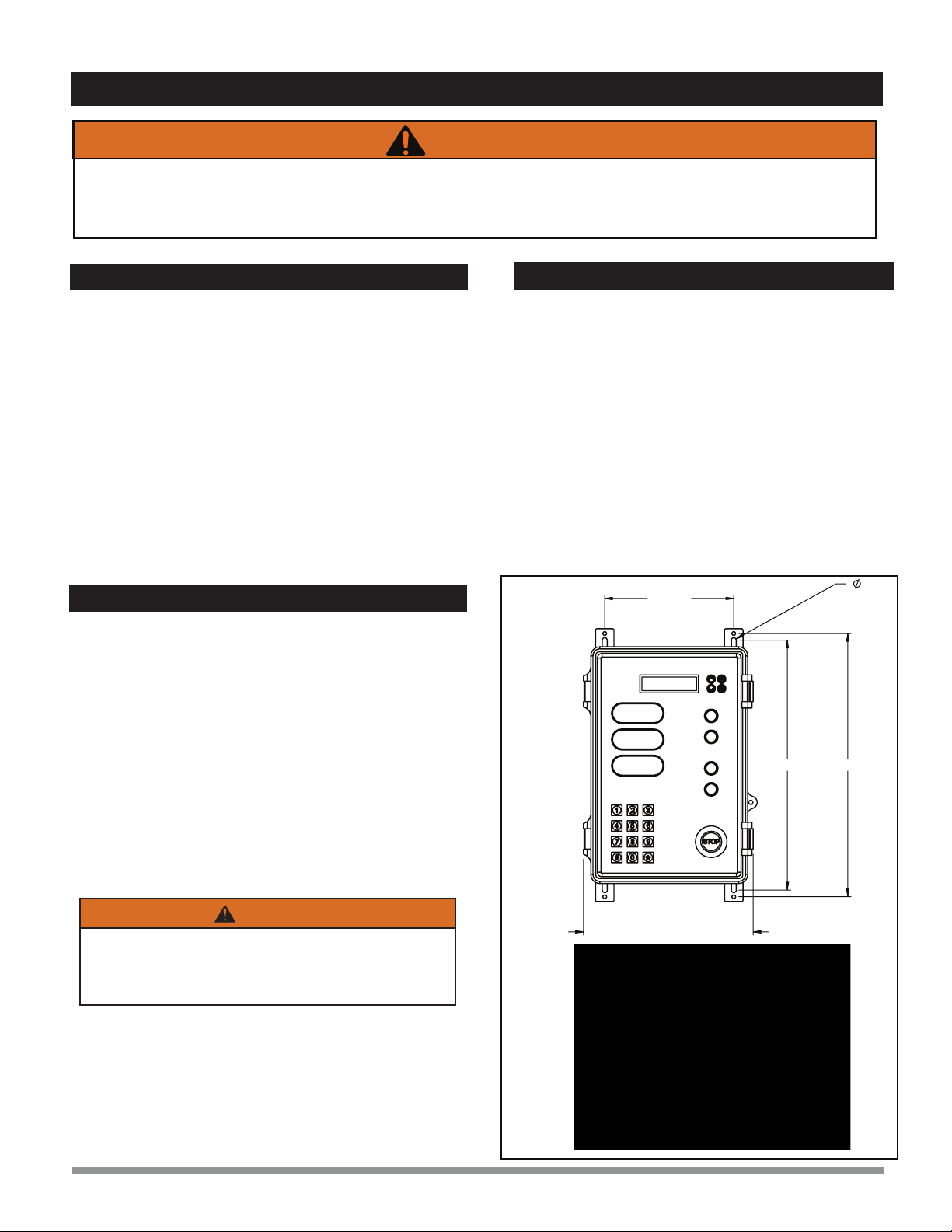
10. CONTROL STATION OPERATION
COMBINATION TYPE CONTROL STATION - Controls XDS3000
R
E
S
T
R
A
I
N
T
RESTRAINT ‘ENGAGE’
(Raise Restraint Arm)
RESTRAINT ‘RELEASE’
(Lower Restraint Arm) CARRIER VEHICLE
RELEASE
Caution
YELLOW LIGHT
(Proceed With Caution)
DDG Manual Control
(Manually raise or lower)
XDS3000 with Blue Genius™ Controls
12

123
456
789
#0*
EnterOnGreen
ProceedWithCaution
DoNotEnter
STOP
Lip
Deck
Release
Engage
SEL
ESC
>
>
1 2 3
6
5
4
789
*
0
#
Restraint
www.BlueGiant.com
Leveler
www.BlueGiant.com
Gold Series
T o u c h C o n t r o l
DISCONNECTPOWER
BEFORE OPENING.
READAND FULLYUNDERSTAND
THEOWNER’S MANUAL BEFORE
OPERATINGTHISPRODUCT.
R
#038-244E
Do Not Enter
Enter On Green
The XDS Dock Leveler with Door and Dock Guard (DDG) and
TL85 vehicle restraint serves as a bridge between a loading
dock and the load bed of a transport vehicle. The raised guard
is designed to prevent forklift roll-off and protect overhead doors
from impact damage.
The rear of a transport vehicle is parked and restrained in place
against the outer wall of the loading dock, in working alignment
with the dock leveler. The hinged lip plate raises with the deck,
its leading edge swinging out horizontally over the rear of the
transporter vehicle once the deck reaches its fully raised
position. The dock attendant releases the touch button, causing
the deck and extended lip to lower together onto the load bed. A
solid bridge is now formed between the dock and the truck.
During loading/unloading operations, both deck and lip
automatically follow the raising and lowering movement of the
transport vehicle. The DDG in combination with the overhead
door sensor provides a safe means of moving between the load
bed and dock during loading and unloading by automatically
activating the DDG if the door happens to close.
Once all work is completed, the dock attendant returns the
leveler to its original stored position.
11.1 Functional Description
11.2 Stop Button Function
Do not operate this leveler unless you have been trained
and authorized to do so, and have read and understood
all of the safety information and instructions contained
herein and on the leveler.
Do not operate the dock leveler beyond its rated
capacity.
Do not operate this leveler until you have checked its
condition. Report the need for repairs to your supervisor
immediately and do not operate the unit until repairs
are made. Neglect may cause a minor repair to become
a major service problem and cause the leveler to become
unsafe.
Never try to lift or move any part of the dock leveler
manually.
Do not drive on the leveler unless the lip is securely on
the truck bed and has a minimum of 4” (100mm) overlap
on its surface.
Do not exceed 4 mph when driving over the dock leveler.
Do not drive over edges of the leveler and / or dock
bumper blocks (bumpers blocks are not structural).
The Blue GeniusTM Control Panel has a temporary ‘STOP’
button for situations where the dock leveler and vehicle restraint
might need to be stopped immediately or left in a certain
position because of an unexpected interference or a potentially
dangerous situation. Touching the ‘STOP’ button during
operation will cause the unit to stop in mid motion.
To exit the ‘STOP’ mode touch ‘ESC’.
11. OPERATING INSTRUCTIONS
STOP
0
ESC
SEL
7 98
4 65
1 32
STOP
D
O
C
K
L
E
V
E
L
E
R
Blue Genius
Proceed With Caution
D
O
C
K
L
E
V
E
L
E
R
DDG
(Door Dock Guard)
XDS
(Extra Dock Safety
dock leveler)
11.3 Deploying the Vehicle Restraint
1. When the unit is first powered on, the DDG will automatically
deploy from the stored to the raised position to prevent forklift
traffic from falling through the door.
Truck / Vehicle Dock Leveler
Vehicle Restraint
ICC Bar
Dock Bumper
Door and Dock Guard
XDS3000 with Blue Genius™ Controls
13

D
O
C
K
L
E
V
E
L
E
R
D
O
C
K
L
E
V
E
L
E
R
11. OPERATING INSTRUCTIONS
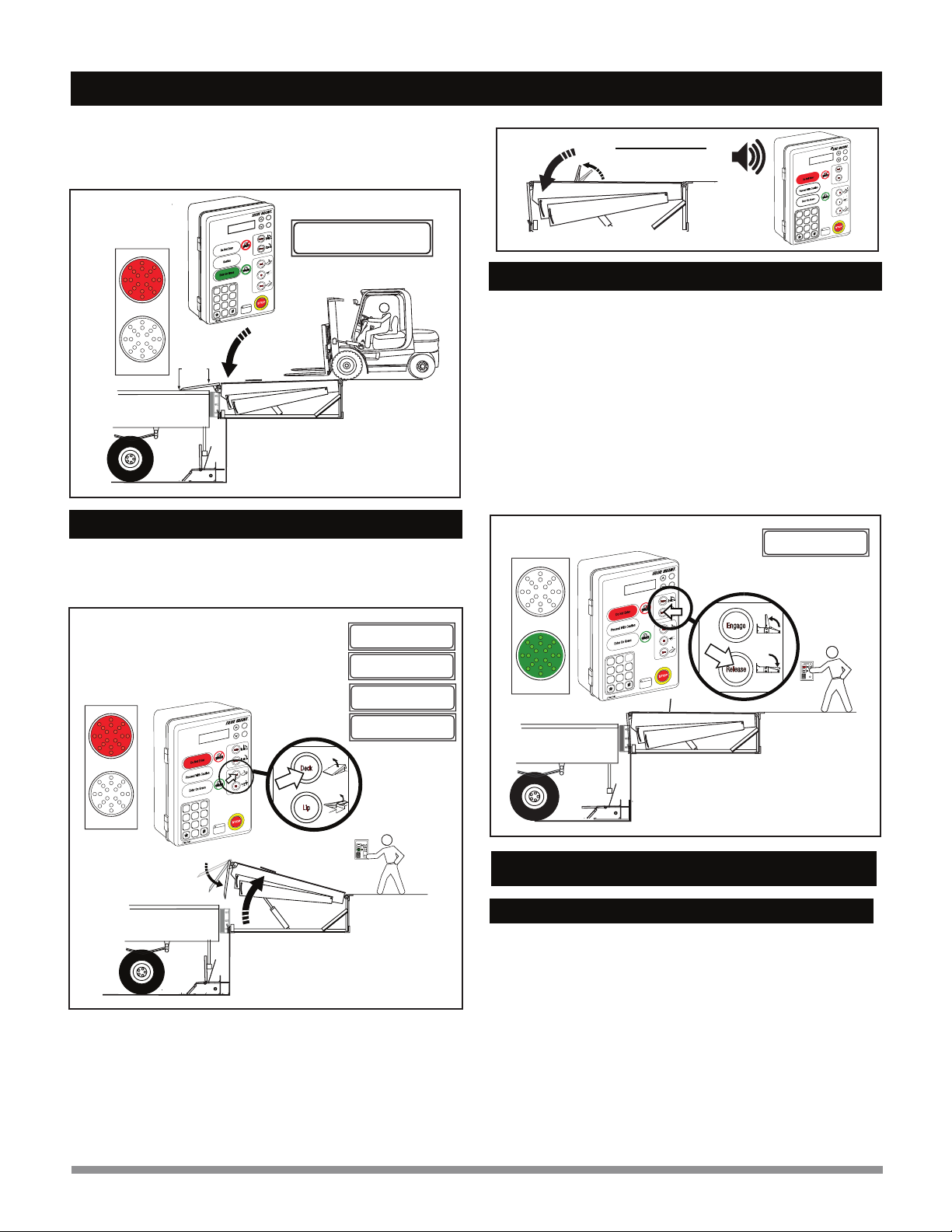
11.4 Operating Procedure (Method 1)
Deploying the XDS Dock (Deck Button Only)
www.BlueGiant.com
GoldSeries
TM
Touch Control
DISCONNECTPOWER
BEFOREOPENING.
READANDFULLYUNDERSTAND
THEOWNER’SMANUALBEFORE
OPERATINGTHISPRODUCT.
WARNING
R
#038-244E
Do Not Enter
Enter On Green
STOP
0
ESC
SEL
97
564
2 31
8
Do Not Enter
.
Caution
Blue Genius
www.BlueGiant.com
Gold Series
TM
Touch Control
DISCONNECTPOWER
BEFORE OPENING.
READANDFULLY UNDERSTAND
THEOWNER’S MANUALBEFORE
OPERATINGTHISPRODUCT.
WARNING
R
#038-244E
Do Not Enter
Enter On Green
STOP
0
ESC
SEL
8 97
5 64
2 31
Dock Leveler
Ready
MENU DISPLAY SCREEN:
Min. 4”
Caution
2. The dock leveler, its lip deployed, will descend onto the
vehicle load bed. The outside traffic light remains RED and
the control station light stays GREEN. Wait for the dock to
fully deploy on the load bed before performing loading /
unloading.
NOTE: Ensure that the full width of the lip overlaps the
vehicle load bed a minimum of 4” (102mm) to provide full
dock leveler support.
Blue Genius
D
O
C
K
L
E
V
E
L
E
R
2. After the truck is parked in place against the dock leveler
bumpers, activate the vehicle restraint by touching the
‘Engage’ button. The outside traffic light turns RED and the
control panel light remains RED. The LCD screen will read
‘Restraint Engaging’. Once the restraint secures the ICC
bar, the message will change to ‘Restraint is Engaged’
followed by ‘Dock Leveler Restored’ and ‘Ready to Raise
Deck’.
NOTE: For vehicles without an ICC bar, please refer to the
‘Manual Override Procedure’.
123
456
789
#0*
EnterOnGreen
ProceedWithCaution
DoNotEnter
STOP
Lip
Deck
Release
Engage
SEL
ESC
>
>
1 2 3
6
5
4
789
*
0
#
Restraint
www.BlueGiant.com
Leveler
www.BlueGiant.com
TM
enius
G
lue
B
T o u c h Con t r o l
DISCONNECTPOWER
BEFORE OPENING.
READANDFULLYUNDERSTAND
THEOWNER’SMANUALBEFORE
OPERATINGTHISPRODUCT.
R
#038-244E
Do Not Enter
Proceed With Caution
STOP
R
E
S
T
R
A
I
N
T
0
ESC
SEL
8 97
56
4
2 31
D
O
C
K
L
E
V
E
L
E
R
123
456
789
#0*
EnterOnGreen
ProceedWithCaution
DoNotEnter
STOP
Lip
Deck
Release
Engage
SEL
ESC
>
>
1 2 3
6
5
4
789
*
0
#
Restraint
www.BlueGiant.com
Leveler
11.5 Deploying the XDS Dock (Deck Button
and Lip Buttons- Method 2)
2. Release the button. The LCD screen reads ‘Deck Moving’.
Both dock leveler and deployed lip will descend onto the
truck bed. The DDG will lower and the onscreen message
will change to ‘Guard Lowering’ followed by ‘Deck
Deployed’. The control panel light will turn GREEN while the
outside traffic light remains RED.
www.BlueGiant.com
TM
enius
G
lue
B
T o u c h Con t r o l
DISCONNECTPOWER
BEFORE OPENING.
READANDFULLYUNDERSTAND
THEOWNER’SMANUALBEFORE
OPERATINGTHISPRODUCT.
R
#038-244E
Do Not Enter
Proceed With Caution
STOP
R
E
S
T
R
A
I
N
T
0
ESC
SEL
8 97
5 64
2 31
1. Touch and hold the ‘Deck’ button. The LCD screen will read
‘Deck Raising’. When the lip has cleared the lip keepers,
release the ‘Deck’ button and touch and hold the ‘Lip’ button.
The LCD screen reads ‘Lip Moving’.
Enter On Green
Enter On Green
D
O
C
K
L
E
V
E
L
E
R
D
O
C
K
L
E
V
E
L
E
R
Restraint Engaging
MENU DISPLAY SCREEN:
Restraint is Engaged
Dock Leveler Restored
Ready to Raise Deck
1. Touch and hold the ‘Deck’ button. The LCD screen will read
‘Deck Raising’ followed by ‘Guard Lowering’. Both the control
panel and outside traffic light are RED. Keep holding the deck
button until the lip deploys.
2. Release the button. The LCD screen reads ‘Deck Moving’. Both
dock leveler and deployed lip will descend onto the truck bed
and the onscreen message will change to ‘Deck Deployed’.
The control panel light will turn GREEN while the outside traffic
light remains RED.
Deck Raising...
MENU DISPLAY SCREEN:
Deck Moving...
Guard Lowering
Deck Deployed
Deck Raising...
MENU DISPLAY SCREEN:
Deck Moving...
Lip Moving...
Guard Lowering
Deck Deployed
XDS3000 with Blue Genius™ Controls
14
D
O
C
K
L
E
V
E
L
E
R
11. OPERATING INSTRUCTIONS
NOTE: Ensure that the full width of the lip overlaps the truck
load bed by a minimum of 4” (102mm) to provide full dock
leveler support.
DockLeveler
Ready
MENU DISPLAY SCREEN:
Min. 4”
www.BlueGiant.com
GoldSeries
TM
enius
G
lue
B
Touch Control
DISCONNECTPOWER
BEFORE OPENING.
READANDFULLY UNDERSTAND
THEOWNER’SMANUAL BEFORE
OPERATINGTHISPRODUCT.
WARNING
R
#038-244E
Do Not Enter
Caution
Enter On Green
STOP
R
E
S
T
R
A
I
N
T
0
ESC
SEL
8 97
5 64
2 31
11.6 Storing the Dock Leveler
1. Touch and hold the ‘Deck’button. The control panel light turns
RED. The deck will raise and the lip will retract. The LCD
screen reads ‘Deck Raising’.
www.BlueGiant.com
GoldSeries
TM
enius
G
lue
B
Touc h Con t rol
DISCONNECTPOWER
BEFORE OPENING.
READANDFULLY UNDERSTAND
THEOWNER’SMANUALBEFORE
OPERATINGTHISPRODUCT.
R
#038-244E
Do Not Enter
Proceed With Caution
Enter On Green
STOP
R
E
S
T
R
A
I
N
T
0
ESC
SEL
8 97
5 64
2 31
D
O
C
K
L
E
V
E
L
E
R
123
456
789
#0*
EnterOnGreen
ProceedWithCaution
DoNotEnter
STOP
Lip
Deck
Release
Engage
1 2 3
6
5
4
789
*
0
#
Restraint
www.BlueGiant.com
Leveler
2. When the lip has fully retracted, release the ‘Deck’button. The
LCD screen will read ‘Deck Moving’ and the deckwill fall to
the stored position with the lip in the lip keepers. The
message will change to ‘Dock Leveler Restored’ followed by
‘Ready to Release’ (refers to the vehicle restraint).
11.7 Undeploying the Restraint Arm
After unchocking the vehicle wheels, release the vehicle
restraint by touching the ‘Release’button. The LCD screen will
read ‘Restraint Releasing’. When the restraint is in the home
position, the message will change to ‘Blue Genius Ready’ and
the control panel light will turn GREEN.
NOTE: If the restraint arm encounters any obstructions that
prevent it from lowering, it will ‘pound’ down two (2) times to
dissolve the blockage. The control panel light will be RED and
accompanied by an intermittent alarm. The LCD screen will
read ‘Arm Blocked- Retrying’ followed by ‘Restraint
Releasing’.After the final unsuccessful attempt, the screen will
read ‘Restraint Arm Blocked’.
www.BlueGiant.com
GoldSeries
TM
enius
G
lue
B
T o uchCon t r o l
DISCONNECTPOWER
BEFORE OPENING.
READANDFULLY UNDERSTAND
THEOWNER’SMANUAL BEFORE
OPERATINGTHISPRODUCT.
R
#038-244E
Do Not Enter
Proceed With Caution
Enter On Green
STOP
R
E
S
T
R
A
I
N
T
ESC
SEL
123
456
789
#0*
EnterOnGreen
ProceedWithCaution
DoNotEnter
STOP
Release
Engage
SEL
ESC
>
>
1 2 3
6
5
4
789
*
0
#
Restraint
www.BlueGiant.com
0
8
9
5 6
2 3
1
4
7
www.BlueGiant.com
TM
Touch Control
DISCONNECTPOWER
BEFORE OPENING.
READANDFULLYUNDERSTAND
THEOWNER’SMANUAL BEFORE
OPERATINGTHISPRODUCT.
WARNING
R
#038-244E
Do Not Enter
Enter On Green
STOP
ESC
SEL
Proceed With Caution
ALARM WILL BEEP WHEN THE
DDG IS DEPLOYED
Optional Alarm
Blue Genius
0
8 97
5 64
2 31
For End Loading Only: Touch the ‘Down’ button. The LCD
message ‘Hold to Lower Guard’ will appear. Hold it for three (3)
seconds. The menu screen will display the message ‘Guard
Lowering’. When the DDG lowers, the control station’sYELLOW
light will come on and remain active for the duration of the
Bypass mode.
NOTE: The DDG can only be lowered when the dock is in the
parked position.Touching the ‘Down button again will bring the
DDG out of Bypass mode.
11.8 DDG - FOR END LOADING / UNLOADING
11.8.1 Lowered / Deactivated Position (Manually)
D
O
C
K
L
E
V
E
L
E
R
Deck Raising...
MENU DISPLAY SCREEN:
Deck Moving...
Dock Leveler Restored
Ready to Release
Restraint Releasing
MENU DISPLAY SCREEN:
XDS3000 with Blue Genius™ Controls
15

D
O
C
K
L
E
V
E
L
E
R
D
O
C
K
L
E
V
E
L
E
R
R
E
S
T
R
A
I
N
T
11. OPERATING INSTRUCTIONS
1. Engage the vehicle restraint (see appropriate section of this
manual). Below level / end loading can take place ONLY after
the freight carrier has been properly restrained.
2. Hold the ‘Deck’ button to raise the deck. Both the control
station light and the outside traffic light are RED.
This section outlines dock leveler operation in situations where
the lip plate cannot make contact with the transport vehicle load
bed. (e.g. Loading / unloading the first skid or pallet from the
load bed when there is insufficient surface area to extend the
dock leveler lip plate.
123
456
789
#0*
EnterOnGreen
ProceedWithCaution
DoNotEnter
STOP
Lip
Deck
Release
Engage
SEL
ESC
>
>
1 2 3
6
5
4
789
*
0
#
Restraint
www.BlueGiant.com
Leveler
3. When the dock is fully raised, the lip extends. With the lip
partially extended (approximately 2” [50mm]) release the
button to return the dock to the stored position. Since the lip
is out and clear of the lip keepers, the dock will descend past
the floor level so that below level / end loading can be
accomplished. The outside traffic light is RED and the control
station light is GREEN. NOTE: Dock personnel must exercise
caution when walking on or around the leveler while it is in the
below level position, as a gap exists between the leveler
edge and the vehicle load bed, and the dock slopes
downward, toward the outside.
123
456
789
#0*
EnterOnGreen
ProceedWithCaution
DoNotEnter
STOP
Lip
Deck
Release
Engage
SEL
ESC
>
>
1 2 3
6
5
4
789
*
0
#
Restraint
www.BlueGiant.com
Leveler
www.BlueGiant.com
TM
enius
G
lue
B
Touch Control
DISCONNECTPOWER
BEFOREOPENING.
READANDFULLYUNDERSTAND
THEOWNER’SMANUALBEFORE
OPERATINGTHISPRODUCT.
WARNING
R
#038-244E
Do Not Enter
Caution
Enter On Green
STOP
R
E
S
T
R
A
I
N
T
0
ESC
SEL
8 97
5 64
2 31
TM
enius
G
lue
B
T o u c h Con t rol
R
Do Not Enter
Proceed With Caution
Enter On Green
STOP
R
E
S
T
R
A
I
N
T
ESC
SEL
8 9
7
5 6
4
2 31
0
eveler
www.BlueGiant.com
GoldSeries
TM
T o u c h C ontrol
DISCONNECTPOWER
BEFOREOPENING.
READANDFULLYUNDERSTAND
THEOWNER’SMANUALBEFORE
OPERATINGTHISPRODUCT.
R
#038-244E
DoNot Enter
EnterOn Green
STOP
0
ESC
SEL
8 97
5 64
23
1
4. Perform below level / end loading or unloading operation.
123
456
789
#0*
EnterOnGreen
ProceedWithCaution
DoNotEnter
STOP
Lip
Deck
Release
Engage
SEL
ESC
>
>
1 2 3
6
5
4
789
*
0
#
Restraint
www.BlueGiant.com
Leveler
Outside Traffic Light
Blue Genius
Caution
123
456
789
#0*
EnterOnGreen
ProceedWithCaution
DoNotEnter
STOP
Lip
Deck
Release
Engage
SEL
ESC
>
>
1 2 3
6
5
4
789
*
0
#
Restraint
www.BlueGiant.com
Leveler
www.BlueGiant.com
GoldSeries
TM
TouchControl
DISCONNECTPOWER
BEFORE OPENING.
READANDFULLY UNDERSTAND
THEOWNER’SMANUAL BEFORE
OPERATINGTHISPRODUCT.
R
#038-244E
Do Not Enter
STOP
0
ESC
SEL
8 97
5 64
2 31
D
Outside Traffic Light
Blue Genius
Caution
11.8.2 Deploying the Dock Leveler- Returning
to Normal Lip-on-Load Bed Operation
1. When below level / end loading has been completed, return
to the normal ‘lip on vehicle load bed’ operation by touching
the ‘Deck’ button until the dock is high enough for the lip to
deploy safely onto the load bed.
R
E
S
T
R
A
I
N
T
Touch the ‘Down’ button. The LCD message ‘Hold to Lower
Guard’ will appear. Hold it for three (3) seconds. The menu
screen will display the message ‘Guard Lowering’. When the
DDG lowers, the control station’s YELLOW light will come on
and remain active for the duration of the Bypass mode.
NOTE: The DDG can only be lowered when the dock is in the
parked position.Touching the ‘Down button again will bring the
DDG out of Bypass mode.
11.8.3 DDG Bypass Mode
Enter On Green
Deck Raising...
MENU DISPLAY SCREEN:
Deck Deployed
MENU DISPLAY SCREEN:
D
O
C
K
L
E
V
E
L
E
R
D
O
C
K
L
E
V
E
L
E
R
www.BlueGiant.com
GoldSeries
TM
enius
G
lu
e
B
T o u c h C o n t r o l
DISCONNECTPOWER
BEFORE OPENING.
READANDFULLYUNDERSTAND
THEOWNER’SMANUAL BEFORE
OPERATINGTHISPRODUCT.
R
#038-244E
Do Not Enter
STOP
0
ESC
SEL
8 97
56
4
2 3
1
Proceed With Caution
Enter On Green
D
O
C
K
L
E
V
E
L
E
R
Guard Lowering
Deck Moving...
MENU DISPLAY SCREEN:
R
E
S
T
R
A
I
N
T
XDS3000 with Blue Genius™ Controls
16

11. OPERATING INSTRUCTIONS
The DDG in conjunction with the overhead door sensor offers
an extra degree of safety during loading and unloading
operations. If the sensor detects that the door has closed, the
DDG is automatically activated, preventing traffic from striking
and damaging the dock door.
As the DDG raises, the optional alarm will sound and the control
station light will change from GREEN to RED. The menu screen
will read ‘ATTENTION! Dock Door Down’ before switching the
message to ‘Dock & Door Guard Up’.
When the door is reopened, the DDG automatically deploys
back to the lowered position for cross traffic. The menu screen
will read ‘Dock & Door Guard Down’ and the control station light
will change from RED to GREEN.
11.9 DDG & Overhead Door Sensor (optional)
DDG is
DEACTIVATED
when overhead
door has passed
sensor range
DDG is
ACTIVATED when
overhead door is in
the sensor range
www.BlueGiant.com
GoldSeries
TM
enius
G
lue
B
T o u c h Con t r o l
DISCONNECTPOWER
BEFOREOPENING.
READANDFULLYUNDERSTAND
THEOWNER’SMANUALBEFORE
OPERATINGTHISPRODUCT.
R
#038-244E
DoNot Enter
EnterOn Green
STOP
R
E
S
T
R
A
I
N
T
0
ESC
SEL
89
7
56
4
2 31
ProceedWith Caution
AT TENTION!
Dock D o or D own
Do ck & D oor
Guar d Up
Dock & D o o r
Guard Down
D
O
C
K
L
E
V
E
L
E
R
www.BlueGiant.com
GoldSeries
TM
enius
G
lue
B
T o u c hC o ntr o l
DISCONNECTPOWER
BEFOREOPENING.
READANDFULLYUNDERSTAND
THEOWNER’SMANUALBEFORE
OPERATINGTHISPRODUCT.
R
#038-244E
DoNot Enter
EnterOn Green
STOP
0
ESC
SEL
897
56
4
2 3
1
ProceedWith Caution
ALARM WILL BEEP WHEN
THE DDG IS RAISED WHEN
DOCK DOOR IS CLOSED
DURING OPERATION
Optional Alarm
DOCK DOOR CLOSES DURING
OPERATION
DOCK DOOR IS OPENED DURING
OPERATION
11.10 Vehicle Restraint Override Feature
1. If the truck has no ICC bar, enter the override code *247 on
the control station keypad. Both the outside traffic light and the
control station light are RED. The control station light will turn
from RED to GREEN and the dock leveler will be ready for use.
2. After loading / unloading is completed and the dock leveler has
been returned to the stored position, remove the wheel chocks,
and reset the control station by touching the restraint’s
‘Release’ button.
XDS3000 with Blue Genius™ Controls
17
Other manuals for BLUE GENIUS SERIES
1
This manual suits for next models
4
Table of contents


