manuals.online logo
Brands
  1. Home
  2. •
  3. Brands
  4. •
  5. Tanda
  6. •
  7. Control Unit
  8. •
  9. Tanda TX7230 User manual

Tanda TX7230 User manual

Other Tanda Control Unit manuals

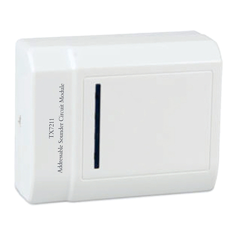
Tanda TX7211 User manual

Tanda

Tanda TX7211 User manual

Tanda TX7210 User manual

Tanda

Tanda TX7210 User manual

Popular Control Unit manuals by other brands

Seitz 14A80 user manual

Seitz

Seitz 14A80 user manual

Wilo RS485 Installation and operating instructions

Wilo

Wilo RS485 Installation and operating instructions

Becker CentralControl CC41 Commissioning Instruction

Becker

Becker CentralControl CC41 Commissioning Instruction

SICK CDB650 operating instructions

SICK

SICK CDB650 operating instructions

Panduit NetKey NKP5E88M Series installation instructions

Panduit

Panduit NetKey NKP5E88M Series installation instructions

MX Options Concentric Petite Fitting instructions

MX

MX Options Concentric Petite Fitting instructions

Clean Water Systems Fleck 2510 Installation & start?up guide

Clean Water Systems

Clean Water Systems Fleck 2510 Installation & start?up guide

Fairchild FSB44104A user guide

Fairchild

Fairchild FSB44104A user guide

LEGRAND Wattstopper LMIN-104 installation instructions

LEGRAND

LEGRAND Wattstopper LMIN-104 installation instructions

PMK ATT10BNCS instruction manual

PMK

PMK ATT10BNCS instruction manual

Tektronix TDS3FFT user manual

Tektronix

Tektronix TDS3FFT user manual

Woodward easYgen Technical manual

Woodward

Woodward easYgen Technical manual

Balluff BNI EIP-502-105-R015 user guide

Balluff

Balluff BNI EIP-502-105-R015 user guide

NXP Semiconductors TWR-LS1021A Getting started

NXP Semiconductors

NXP Semiconductors TWR-LS1021A Getting started

Advantech PCM-3117 Startup manual

Advantech

Advantech PCM-3117 Startup manual

Danfoss MCO 101 manual

Danfoss

Danfoss MCO 101 manual

Moons' Lin Engineering R701P user manual

Moons'

Moons' Lin Engineering R701P user manual

Aventics RV1 operating instructions

Aventics

Aventics RV1 operating instructions

manuals.online logo
manuals.online logoBrands
  • About & Mission
  • Contact us
  • Privacy Policy
  • Terms and Conditions

Copyright 2025 Manuals.Online. All Rights Reserved.

TX7230
Isolator Module
Installation and Operation Manual
TANDA UK Technology Copyright ©2015, All right reserved.
TX7230 Isolator Module
Installation & Operation Manual
4050100319-Rev1.6-0916
TANDA UK
Specifications are subject to change without prior notice
2
Product Safety
To prevent severe injury and loss of life or property, read the instruction carefully before installing the
module to ensure proper and safe operation of the system.
European Union directive
2012/19/EU (WEEE directive): Products marked with this symbol cannot be disposed
of as unsorted municipal waste in the European Union. For proper recycling, return
this product to your local supplier upon the purchase of equivalent new
equipment, or dispose of it at designated collection points.
For more information please visit the website at www.recyclethis.info
EN54 Part 17 Compliance
TX7230 Isolator Module complies with the requirements of EN 54-17:2005.
EN54 Standard Conformity Information
0832
17
TANDA(UK) LIMTIED
FOURTH FLOOR 30-31 FURNIVAL STREET LONDON EC4A
1JQ(Type 1, Option 2 Crosslisting)
TX7230 0832-CPR-F1831
EN 54-17:2005
TX7230 Isolator Module
Installation & Operation Manual
4050100319-Rev1.6-0916
TANDA UK
Specifications are subject to change without prior notice
3
Table of Content
1 Introduction .................................................................................................................................................. 4
1.1 Overview ................................................................................................................................................ 4
1.2 Feature and Benefits ........................................................................................................................... 4
1.3 Technical Specification ..................................................................................................................... 4
2 Installation ..................................................................................................................................................... 5
2.1 Installation Preparation ...................................................................................................................... 5
2.2 Installation and Wiring ........................................................................................................................ 5
3 General Maintenance .............................................................................................................................. 6
4 Troubleshooting Guide .............................................................................................................................. 6
Appendix 1 ....................................................................................................................................................... 6
Limitation of Isolator Module ................................................................................................................... 6
TX7230 Isolator Module
Installation & Operation Manual
4050100319-Rev1.6-0916
TANDA UK
Specifications are subject to change without prior notice
4
1 Introduction
1.1 Overview
The TX7230 manufactured base on the requirement of EN 54 part 17, European Standard. In the
event of short circuit on the detection loop the TX7230 Isolators either side of the loop will detect the
problem and open circuit and isolates the faulty part of the loop, enabling other devises on the
unaffected part of the loop to operate normally. The module will continue to monitor for the fault to
be repaired, once the fault is cleared the isolator will automatically reinstate the effected part of the
loop.
The unit is aesthetically pleasing with unobtrusive design that will complement modern building
designs and its plug-in type assembles make installation and maintenance more convenient to the
installer. The TX7230 Isolators Module is compatible to the TX7004 Analogue Intelligent Fire Alarm
Control Panel, produced by single manufacture T&A, to avoid addressable communication
compatibility problem.
1.2 Feature and Benefits
 EN54-17 Compliance
 In the event of a short circuit isolates faulty parts of the loop.
 Automatically resetting once the fault has cleared
 Can monitor up to 70 devices
 LED status indicator
 Loop powered device
 Aesthetically pleasing design
 Surface mounting with fix base for simple installation
1.3 Technical Specification
 Listed LPCB Certification
 Compliance EN 54-17:2005
 Maximum Operating Voltage(VMAX) 28VDC
 Operating Voltage(VNOM) 24V
 Minimum Operating Voltage(VMIN) 16V
 Maximum Open Voltage(VSO MAX) 11V
 Minimum Open Voltage(VSO MIN) 8V
 Maximum Close Voltage(VSC MAX) 3V
 Minimum Close Voltage(VSC MIN) 1.4V
 Maximum Continuous Current(IC MAX) 500mA
 Maximum Transient Output Current(IS MAX) 5A
 Maximum Leakage Current(IL MAX) 2mA
 Max closed impedance (ZC MAX) 0.65 ohms
 Current Consumption Standby 0.15mA, Alarm: 1.8mA
 Protocol T&A
 Number of monitored Max 70 Devices
 Output Impedance 480 ohms
 Indicator Status Normal: Single blink/Active: Steady-on
 Material / Colour ABS / White Glossy finishing
 Dimension / LWH 108 mm x 86 mm x38 mm
 Weight 152g (with Base), 81g (without Base)
 Operating Temperature -10°C to +50°C
 Ingress Protection Rating IP30
 Humidity 0 to 95% Relative Humidity, Non condensing
TX7230 Isolator Module
Installation & Operation Manual
4050100319-Rev1.6-0916
TANDA UK
Specifications are subject to change without prior notice
5
2 Installation
2.1 Installation Preparation
This interface module must be installed, commissioned and maintained by a qualified or factory
trained service personnel. The installation must be installed in compliance with all local codes having
a jurisdiction in your area or BS 5839 Part 1 and EN54.
T&A products has available range of interfaces, each interface module is designed for specific
application, it is essential to consider the requirement of both sides of the interface to avoid
malfunction and typical fault scenario. The main caution is to ensure that the voltage rating of the
equipment and interface module are compatible.
2.2 Installation and Wiring
1. Mount the interface module base on standard one gang electrical back box. Follow the
arrow mark for the correct position. Do not over-tighten the screws otherwise the base will
twist. Use two M4 standard screws.
2. Connect the wire in terminal as shown in Figure two [2].
3. Align the interface module and tabs and gently pushing the device until it locks into place.
Terminal Description
Z1 Signal In (+)
Z3 Signal Out (+)
Z2 Signal In (-)
Z4 Signal Out (-)
Figure 2: wiring
Figure 1
TX7230 Isolator Module
Installation & Operation Manual
4050100319-Rev1.6-0916
TANDA UK
Specifications are subject to change without prior notice
6
3 General Maintenance
1. Inform the suitable personnel before conducting the maintenance.
Note: Since Isolator cannot disable from the control panel to prevent false alarm, it is
recommended to temporarily close the loop once the isolator is removed.
2. Do not attempt to repair the circuitry of the interface module, it may affect the operation to
respond to a fire condition and will void the manufacturer’s warranty.
3. Use a damp cloth to clean the surface.
4. Notify again proper personnel after conducting the maintenance and make sure to enable
the interface module and confirm if up and running.
5. Perform the maintenance on semi-annually or depending on the site conditions.
4 Troubleshooting Guide
What you notice What it means What to do
Panel display loop fault Wrong wiring or the damage the
electronic circuit Replace the device
Appendix 1
Limitation of Isolator Module
The Module cannot last forever. In order to keep the module working in good condition, please
maintain the equipment continuously according to recommendations from manufacturers and
relative nation codes and laws. Take specific maintenance measures on the basis of different
environments.
This module contains electronic parts. Even though it is made to last for a long period of time, any of
these parts could fail at any time. Therefore, test your module at least every half-year according to
national codes or laws. Any interface module, fire alarm devices or any other components of the
system must be repaired and/or replaced immediately as they fail.