Blue Giant EPS-22 User manual
OWNER’S MANUAL
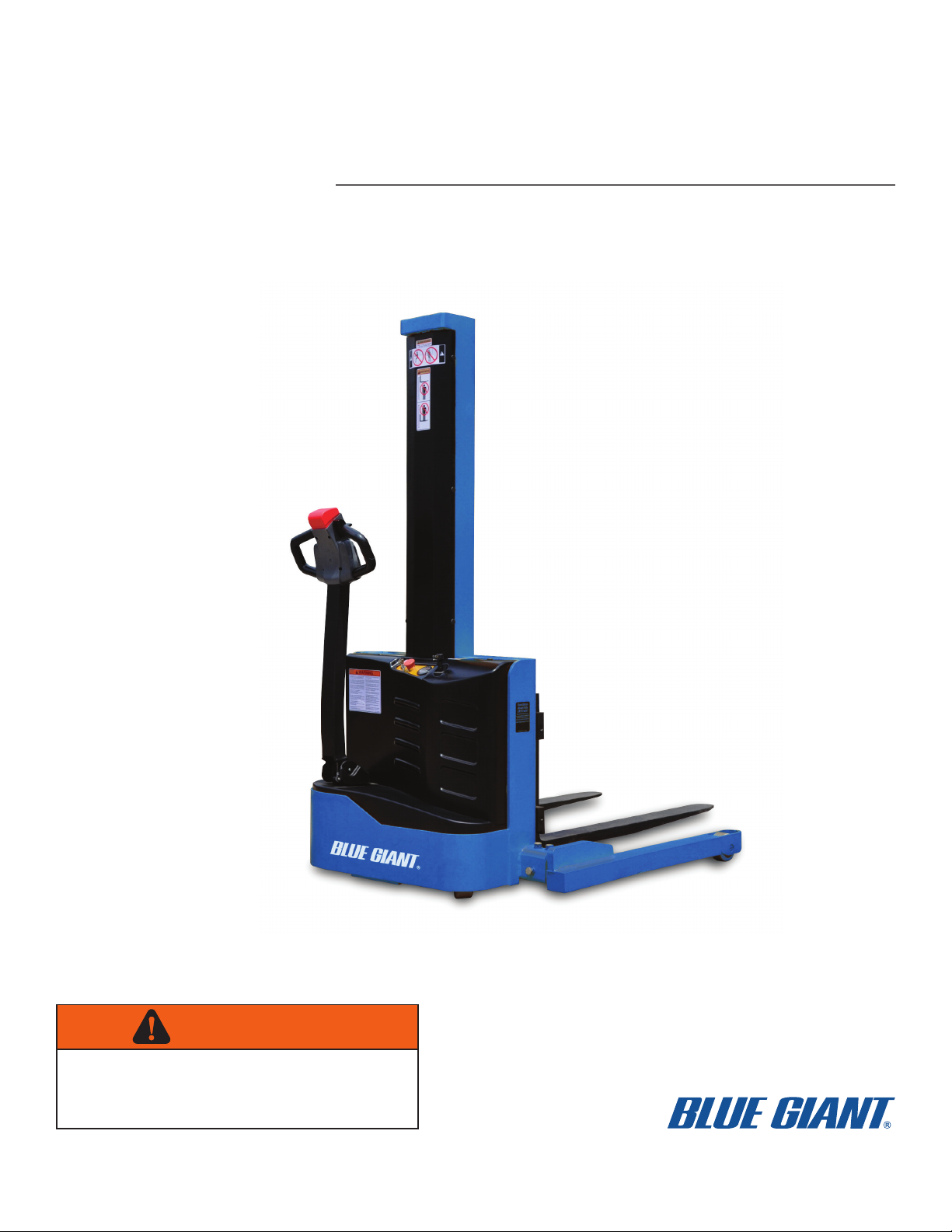
EPS-22 POWERED STRADDLE TRUCK
ISSUE DATE:APRIL 3, 2014 REV.0 (PART # 038-925E)
WARNING
Do not operate or service this product unless you have
read and fully understand the entire contents of this
manual. Failure to do so may result in property damage,
bodily injury or death.

WARNING
Do not operate this truck unless you have been autho-
rized and trained to do so, and have read all warnings
and instructions in Operator’s Manual and on this
truck.
Do not operate this truck until you have checked its
condition. Give special attention to tires, horn, battery,
controller, lift system (including forks or attachments,
chains, cables and limit switches), brakes, steering
mechanism, guards and safety devices.
Operate truck only from designated operating position.
Never place any part of your body into the mast struc-
ture or between the mast and the truck. Do not carry
passengers. Keep feet clear of truck and wear foot
protection.
Observe applicable traffic regulations. Yield right of
way to pedestrians. Slow down and sound horn at
cross aisles and wherever vision is obstructed.
Start, stop, travel, steer and brake smoothly. Slow
down for turns and on uneven or slippery surfaces that
could cause truck to slide or overturn. Use special
care when traveling without load as the risk of overturn
may be greater.
Travel with lifting mechanism as low as possible.
Always look in direction of travel. Keep a clear view,
and when load interferes with visibility, travel with load
trailing.
Use special care when operating on ramps travel
slowly, and do not angle or turn. Travel with load
downhill.
Do not overload truck. Check nameplate for capacity
and load center information.
When using forks, space forks as far apart as load will
permit. Before lifting, be sure load is centered, forks
are completely under load, and load is as far back as
possible against load backrest.
Do not handle unstable or loosely stacked loads. Use
special care when handling long, high or wide loads, to
avoid losing the load, striking bystanders, or tipping
the truck.
Do not handle loads which are higher than the load
backrest or load backrest extension unless load is
secured so that no part of it could fall backward.
Elevate forks or other lifting mechanism only to pick up
or stack a load. Watch out for obstructions, especially
overhead.
Do not lift personnel except on a securely attached
specially designed work platform. USE EXTREME
CARE WHEN LIFTING PERSONNEL. Make sure
mast is vertical, place truck controls in neutral and
apply brakes. Lift and lower smoothly. Remain in oper-
ating position or immediate vicinity as long as person-
nel are on the work platform. Never transport
personnel on forks or work platform.
Do not allow anyone to stand or pass under load or lift-
ing mechanism.
When leaving truck, neutralize travel control, fully
lower lifting mechanism and set brake. When leaving
truck unattended, also shut off power.

TABLE OF CONTENTS
BG-S22-0812 i
Section Page Section Page
1 DESCRIPTION ............................................................1-1
1-1. INTRODUCTION. .........................................1-1
1-2. GENERAL DESCRIPTION. ..........................1-1
1-3. SAFETY FEATURES....................................1-1
2 OPERATION ...............................................................2-1
2-1. GENERAL.....................................................2-1
2-2. OPERATING PRECAUTIONS......................2-1
2-3. BEFORE OPERATION.................................2-2
2-4. GENERAL CONTROL OPERATION............2-4
2-5. DRIVING AND STOPPING PROCEDURES.2-4
2-5.1. STOPPING ...................................................2-4
2-6. BELLY-BUTTON SWITCH............................2-5
2-7. STEERING ARM GAS SPRING. ..................2-5
2-8. LIFT AND LOWER CONTROLS...................2-5
2-9. LOADING AND UNLOADING.......................2-5
2-10. PARKING......................................................2-5
3 PLANNED MAINTENANCE ........................................3-1
3-1. GENERAL.....................................................3-1
3-2. MONTHLY AND QUARTERLY CHECKS.....3-1
3-3. BATTERY CARE. .........................................3-1
3-3.1. GENERAL ....................................................3-1
3-3.2. SAFETY RULES...........................................3-2
3-3.3. BATTERY CARE AND CHARGING .............3-2
3-3.4. BATTERY CLEANING..................................3-2
3-3.5. MAINTENANCE FREE BATTERIES............3-2
3-4. CHARGING BATTERIES..............................3-3
3-5. CHARGING BATTERIES..............................3-3
3-6. LUBRICATION..............................................3-4
3-7. LIFT CHAIN MAINTENANCE. ......................3-4
4 TROUBLESHOOTING ................................................4-1
4-1. GENERAL.....................................................4-1
4-2. CONTROLLER TROUBLESHOOTING ........4-4
4-2.1. FAULT DETECTION. ...................................4-4
4-2.2. HAND HELD PROGRAMMER (OPTIONAL)4-4
4-2.3. FAULT RECORDING. ..................................4-4
4-2.4. GENERAL CHECKOUT. ..............................4-4
4-2.5. DIAGNOSTIC HISTORY ..............................4-6
4-2.6. TEST THE FAULT DETECTION
CIRCUITRY ..................................................4-6
4-2.7. PROGRAMMABLE PARAMETERS .............4-6
4-2.8. DIAGNOSTICS AND
TROUBLESHOOTING. .............................4-15
4-2.9. PROGRAMMER DIAGNOSTICS ...............4-15
5 STEERING ARM, CONTROL HEAD AND
COMPARTMENT ........................................................5-1
5-1. CONTROL HEAD .........................................5-1
5-1.1. CAP ASSEMBLY REMOVAL. ......................5-1
5-1.2. CAP ASSEMBLY INSTALLATION. ..............5-2
5-1.3. CONTROL HEAD REMOVAL ......................5-3
5-1.4. CONTROL HEAD INSTALLATION ..............5-3
5-1.5. SPEED POTENTIOMETER
REPLACEMENT...........................................5-3
5-1.6. BELLY-BUTTON SWITCH
REPLACEMENT...........................................5-3
5-1.7. HORN SWITCH REPLACEMENT. .............. 5-4
5-1.8. LIFT AND LOWER SWITCH
REPLACEMENT. ......................................... 5-6
5-2. STEERING ARM .......................................... 5-6
5-2.1. RETURN SPRING REPLACEMENT. .......... 5-6
5-2.2. STEERING ARM REMOVAL. ...................... 5-6
5-2.3. STEERING ARM INSTALLATION. .............. 5-6
5-3. COMPARTMENT COVERS ......................... 5-6
5-3.1. REMOVAL. .................................................. 5-6
5-3.2. INSTALLATION. .......................................... 5-6
5-4. MONO MAST COVER ................................. 5-7
5-4.1. REMOVAL. .................................................. 5-7
5-4.2. INSTALLATION. .......................................... 5-7
6 BRAKE SERVICING ................................................... 6-1
6-1. BRAKES....................................................... 6-1
6-1.1. BRAKE ASSEMBLY REPLACEMENT ........ 6-1
7 TRANSMISSION, DRIVE WHEEL, LOAD WHEEL .... 7-1
7-1. DRIVE WHEEL. ........................................... 7-1
7-2. TRANSMISSION.......................................... 7-1
7-3. LOAD WHEEL.............................................. 7-3
7-3.1. REMOVAL ................................................... 7-3
7-3.2. REPAIR....................................................... 7-3
7-3.3. LOAD WHEEL INSTALLATION................... 7-3
8 ELEVATION SYSTEM SERVICING ........................... 8-1
8-1. GENERAL. ................................................... 8-1
8-2. LIFT CHAIN LENGTH ADJUSTMENT......... 8-1
8-2.1. MONO.......................................................... 8-1
8-2.2. TELESCOPIC .............................................. 8-2
8-3. LIFT CHAIN WEAR INSPECTION............... 8-2
8-4. LIFT CHAIN REPLACEMENT...................... 8-3
8-4.1. MONO.......................................................... 8-3
8-4.2. TELESCOPIC .............................................. 8-3
8-5. LIFT CYLINDERS. ....................................... 8-3
9 HYDRAULIC SYSTEM SERVICING........................... 9-1
9-1. LINES AND FITTINGS................................. 9-1
9-2. HYDRAULIC PUMP, MOTOR, AND
RESERVOIR ASSY ..................................... 9-2
9-2.1. REMOVAL ................................................... 9-3
9-2.2. DISASSEMBLY AND REASSEMBLY.......... 9-3
9-2.3. INSTALLATION ........................................... 9-3
9-3. LIFT CYLINDER (MONO) ............................ 9-3
9-3.1. REMOVAL ................................................... 9-3
9-3.2. REPAIR........................................................ 9-5
9-3.3. INSTALLATION ........................................... 9-5
9-4. LIFT CYLINDER (TELESCOPIC)................. 9-6
9-4.1. REMOVAL ................................................... 9-6
9-4.2. REPAIR........................................................ 9-6
9-4.3. INSTALLATION ........................................... 9-8
10 ELECTRICAL COMPONENTS ................................. 10-1
10-1. ELECTRICAL CONTROL PANEL.............. 10-1
10-1.1. MAINTENANCE......................................... 10-1
10-1.2. CLEANING................................................. 10-1
10-1.3. CONTROLLER REMOVAL........................ 10-1
10-1.4. CONTROLLER INSTALLATION................ 10-1

TABLE OF CONTENTS
ii BG-S22-0812
Section Page Section Page
10-1.5. CHARGER REMOVAL. ............................. 10-1
10-1.6. CHARGER INSTALLATION....................... 10-1
10-1.7. COOLING FAN REMOVAL (MONO). ........ 10-4
10-1.8. COOLING FAN INSTALLATION (MONO). 10-4
10-1.9. BUZZER REMOVAL. ................................. 10-4
10-1.10. BUZZER INSTALLATION. ......................... 10-4
10-1.11. KEY SWITCH REMOVAL. ......................... 10-4
10-1.12. KEY SWITCH INSTALLATION. ................. 10-4
10-1.13. BATTERY INDICATOR REMOVAL. .......... 10-4
10-1.14. BATTERY INDICATOR INSTALLATION. .. 10-4
10-1.15. LED INDICATOR REMOVAL..................... 10-5
10-1.16. LED INDICATOR INSTALLATION............. 10-5
10-1.17. EMERGENCY DISCONNECT REMOVAL. 10-5
10-1.18. EMERGENCY DISCONNECT
INSTALLATION..........................................10-5
10-1.19. LIFT LIMIT SWITCH REMOVAL. ...............10-5
10-1.20. LIFT LIMIT SWITCH INSTALLATION. .......10-5
10-2. PUMP MOTOR. ..........................................10-5
10-3. DRIVE MOTOR. .........................................10-5
10-4. DEADMAN SWITCH...................................10-6
11 OPTIONAL EQUIPMENT..........................................11-1
11-1. LOAD BACKREST...................................... 11-1
12 ILLUSTRATED PARTS BREAKDOWN ....................12-1
LIST OF ILLUSTRATIONS
Figure Page Figure Page
1-1 NAME PLATE....................................................... 1-1
1-2 S22 LIFT TRUCK ................................................. 1-2
2-1 LOAD CENTER .................................................... 2-1
2-2 SAMPLE OF OPERATOR CHECK LIST.............. 2-3
2-3 FORWARD/REVERSE CONTROL ...................... 2-4
2-4 PUSHBUTTON SWITCHES................................. 2-4
2-5 BRAKE ACTUATION............................................ 2-5
2-6 BELLY-BUTTON SWITCH ................................... 2-5
3-1 BATTERY CHARGING......................................... 3-3
3-2 BATTERY CHARGING......................................... 3-4
3-3 BATTERY CHARGING......................................... 3-4
3-4 LUBRICATION DIAGRAM.................................... 3-5
4-1 CONTROLLER TERMINALS ............................... 4-4
4-2 HAND HELD PROGRAMMER ............................. 4-4
5-1 CONTROL HEAD ................................................. 5-1
5-2 STEERING ARM .................................................. 5-2
5-3 EMERGENCY REVERSE SWITCH ASSEMBLY. 5-4
5-4 CAP ASSEMBLY.................................................. 5-5
6-1 TRANSMISSION, MOTOR, BRAKE ASSEMBLY 6-2
7-1 TRANSMISSION, MOTOR, BRAKE MOUNTING 7-2
8-1 CHAIN ASSEMBLY (MONO) ............................... 8-1
8-2 CHAIN ASSEMBLY (TELESCOPIC).................... 8-2
9-1 HYDRAULIC SYSTEM (MONO) .......................... 9-1
9-2 HYDRAULIC SYSTEM (TELESCOPIC)............... 9-2
9-3 ELEVATION SYSTEM (MONO) ........................... 9-4
9-4 LIFT CYLINDER (MONO) .................................... 9-5
9-5 LIFT CYLINDER (TELESCOPIC)......................... 9-6
9-6 ELEVATION SYSTEM (TELESCOPIC) ............... 9-7
10-1 ELECTRICAL SYSTEM (MONO) ....................... 10-2
10-2 ELECTRICAL SYSTEM (TELESCOPIC)............ 10-3
12-1 STEERING SYSTEM.......................................... 12-2
12-2 CONTROL HEAD ............................................... 12-4
12-3 CAP ASSEMBLY ................................................ 12-6
12-4 EMERGENCY REVERSE SWITCH ASSEMBLY 12-8
12-5 TRANSMISSION, MOTOR, BRAKE ASSEMBLY. 12-
10
12-6 COMPARTMENT, MONO................................. 12-12
12-7 COMPARTMENT, TELESCOPIC ..................... 12-14
12-8 ADJUSTABLE STRADDLE, MONO ................. 12-16
2-9 ADJUSTABLE STRADDLE, TELESCOPIC...... 12-18
12-10 CASTER ........................................................... 12-20
12-11 ELEVATION SYSTEM (MONO) ....................... 12-22
12-12 ELEVATION SYSTEM (TELESCOPIC)............ 12-24
12-13 LIFT CARRIAGE (MONO) ................................ 12-26
12-14 LIFT CARRIAGE (TELESCOPIC)..................... 12-28
12-15 CHAIN ASSEMBLY (MONO)............................ 12-30
12-16 CHAIN ASSEMBLY (TELESCOPIC) ................ 12-31
12-17 HYDRAULIC SYSTEM (MONO)....................... 12-32
12-18 HYDRAULIC SYSTEM (TELESCOPIC) ........... 12-33
12-19 PUMP & MOTOR ASSY ................................... 12-34
12-20 LIFT CYLINDER (MONO)................................. 12-36
12-21 LIFT CYLINDER (TELESCOPIC) ..................... 12-37
12-22 ELECTRICAL SYSTEM (MONO) ..................... 12-38
12-23 ELECTRICAL SYSTEM (TELESCOPIC).......... 12-40
12-24 WIRING HARNESS (MONO)............................ 12-42
12-25 WIRING HARNESS (TELESCOPIC) ................ 12-43
12-26 WIRING CABLES (MONO)............................... 12-44
12-27 WIRING CABLES (TELESCOPIC) ................... 12-45
LIST OF TABLES
Table Page Table Page
2-1 OPERATOR CHECKS........................................... 2-2
3-1 MONTHLY AND QUARTERLY INSPECTION
AND SERVICE CHART ......................................... 3-1
3-2 RECOMMENDED LUBRICANTS .......................... 3-4
3-3 LUBRICATION CHART ......................................... 3-5
4-1 TROUBLESHOOTING CHART..............................4-1
4-2 PROGRAMMABLE PARAMETERS.......................4-7
4-3 LED CODES ........................................................4-15
4-4 TROUBLESHOOTING CHART............................ 4-16
BG-S22-0812 1-1
SECTION 1
DESCRIPTION
1-1. INTRODUCTION.
This publication describes the 24 volt transistor
S22 lift truck distributed by Big Lift LLC. Included are
operating instructions, planned maintenance instruc-
tions, lubrication procedures, corrective maintenance
procedures and a complete parts list with part location
illustrations.
Users shall comply with all requirements indicated in
applicable OSHA standards and current edition of
A.N.S.I. B56.1 Part II. By following these requirements
and the recommendations contained in this manual,
you will receive many years of dependable service
from your S22 lift truck.
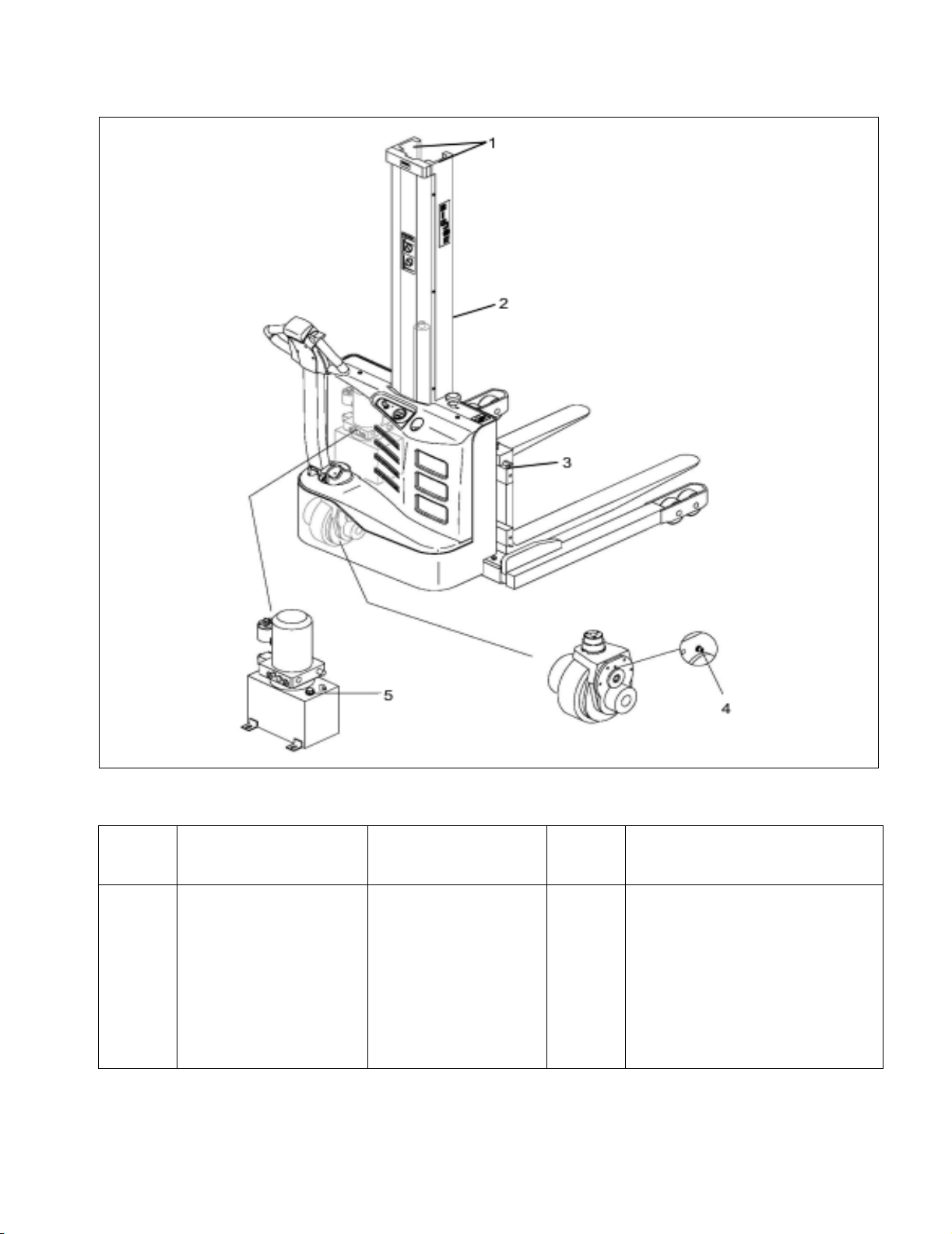
1-2. GENERAL DESCRIPTION.
The self-propelled S22 truck, Figure 1-2, lifts and
transports payloads up to 2200 pounds on adjustable
forks.
The S22 Mono truck has a 62 inch lift. The S22 Tele-
scopic truck has either a 96 or 116 inch lift.
The forward and reverse motion is controlled by either
of two controller levers mounted on the control head.
Stopping and turning is controlled by the steering arm.
Lift and Lower is controlled by pushbuttons on the con-
trol head. The battery powered lift truck is quiet and
without exhaust fumes.
The reversible AC motor propels the lift truck in for-
ward or reverse direction throughout the available
speed range. The S22 lift truck can be driven with
forks raised or lowered; however, the speed is
restricted when the platform is raised above a preset
limit.
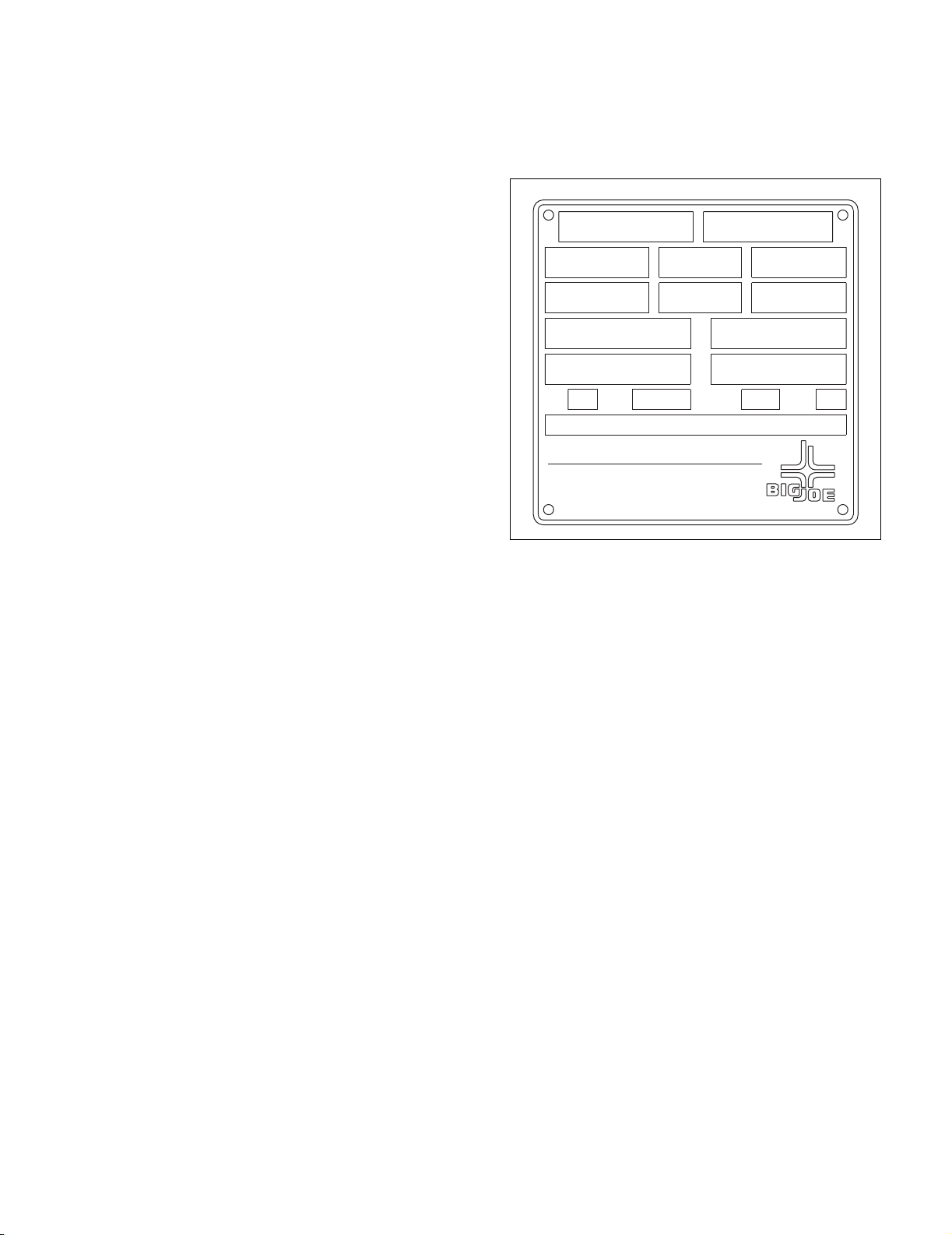
The model number will be found on the name plate
(Figure 1-1) along with the serial number, lifting capac-
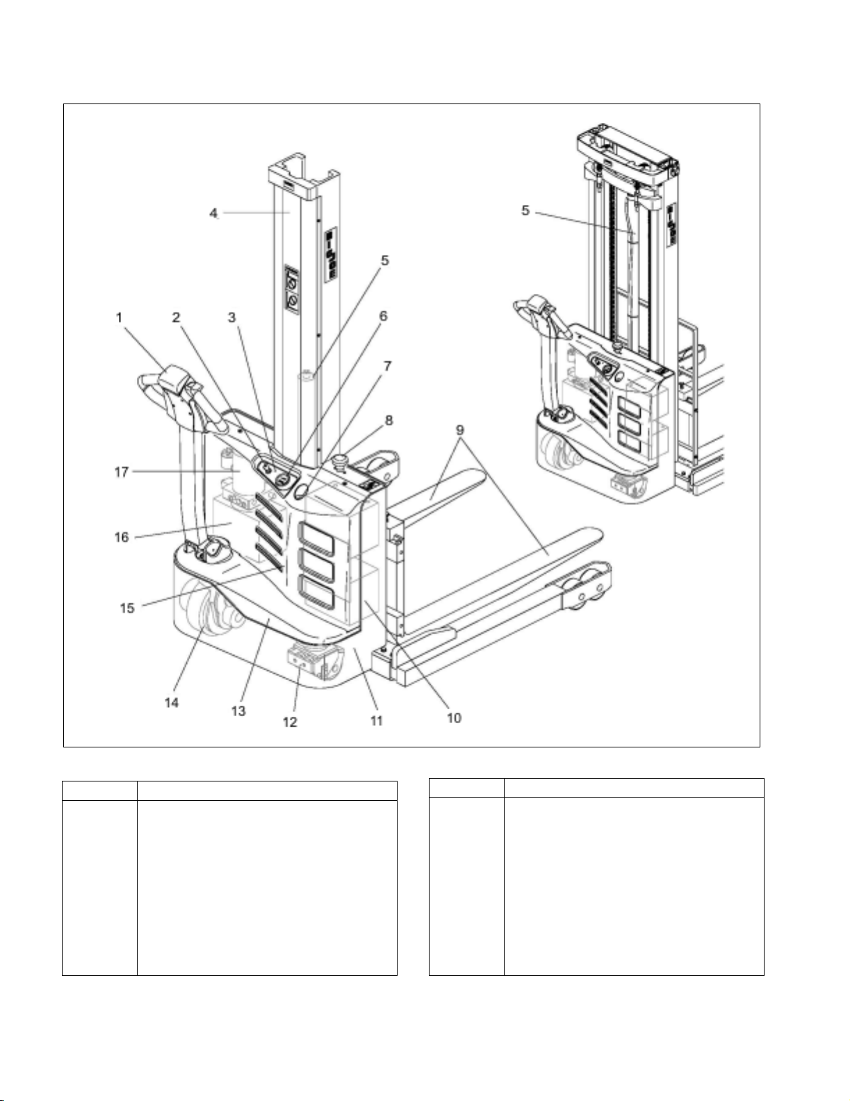
ity, and load center. Figure 1-2 shows the locations of
the truck’s main components and controls.
1-3. SAFETY FEATURES.
The S22 is designed engineered to provide maximum
safety for operator and payload. Some of the safety
features incorporated into the design are:
Figure 1-1 Name Plate
• Dead-man brake to apply the brake and cut off drive
power when the steering arm is released.
• Emergency brake switch to apply the brake and cut
off drive power when depressed.
• Belly-button switch to reverse truck should the oper-
ator accidentally pin himself against a wall or
obstruction when backing up in slow speed.
• High speed limit switch to restrict speed when lift
carriage is raised above the preset limit.
• All control functions automatically return to “OFF”
when released.
• Externally accessible emergency stop switch within
operator's reach.
• Separately fused control circuits and power circuits.
• Readily accessible horn button.
• Lift carriage backrest to help stabilize the load.
• Handle to provide a firm hand hold for operator.
• Flow control valve regulates maximum lowering
speed within prescribed limits.
• Relief valve maintains hydraulic pressure within pre-
scribed limits.
• High visibility color scheme of truck provides visual
alert of truck’s presence.
• Battery Indicator
•Caster.
COMPLIES WITH THE APPLICABLE REQUIRE-COMPLIES WITH THE APPLICABLE REQUIRE-
MENTS OF ANSI B56.1 AND OSHA STANDARDSMENTS OF ANSI B56.1 AND OSHA STANDARDS
BIG LIFT LLCBIG LIFT LLC
WISCONSIN DELLS, WISCONSIN 53965WISCONSIN DELLS, WISCONSIN 53965
AUSTRALIAN PATENT NO. 537,987AUSTRALIAN PATENT NO. 537,987
U.S. PATENT NO. 4,444,284U.S. PATENT NO. 4,444,284
TRUCK
TYPE
MODEL NO. SERIAL NO.
VOLTAGE
BATTERY
TYPE CERTIFIED
MAX CAP LB/MAX CAP LB/ LOAD CTR IN/LOAD CTR IN/ LIFT HGT IN/
LOAD CTR IN/LOAD CTR IN/ LIFT HGT IN/ALT CAP LB/
BATTERY MIN WT LB/BATTERY MIN WT LB/TRUCK WT LESS BATTERY LB/TRUCK WT LESS BATTERY LB/
BATTERY MAX WT LB/BATTERY MAX WT LB/TRUCK WT WITH BATTERY LB/TRUCK WT WITH BATTERY LB/
KG MM MM
MM MMKG
KGKG
KGKG
R6209
1-2 BG-S22-0812
Figure 1-2 S22 Lift Truck
R6841
ITEM COMPONENT
1 Control handle.
2 Key switch
3LEDindicator
4 Mast cover
5 Lift cylinder
6 Battery indicator
7 Battery charger connector
8 Emergency brake switch
9Forks
10 Battery
11 Chassis
12 Caster
13 Cover
14 Drive wheel
15 Cover
16 Hydraulic reservoir
17 Hydraulic pump
ITEM COMPONENT
BG-S22-0812 2-1
SECTION 2
OPERATION
2-1. GENERAL.
This section gives detailed operating instructions for
the S22 lift truck. The instructions are divided into the
various phases of operations, such as operating lift,
driving, and stopping. Routine precautions are
included for safe operation.
2-2. OPERATING PRECAUTIONS.
WARNING: Improper operation of the lift truck may
result in operator injury, or load and/or lift
truck damage. Observe the following
precautions when operating the S22 lift
truck.
The following safety precautions must be adhered to
at all times.
• Do not operate this truck unless you have been
trained and authorized to do so.
• All warnings and instructions must be read and
understood before using the equipment.
• Equipment must not be altered in any way.
• Equipment must be inspected by a qualified person
on a regular basis.
• Do not exceed the rated capacity. Overloading may
result in damage to the hydraulic system and struc-
tural components.
• Be certain that the lifting mechanism is operating
smoothly throughout its entire height, both empty
and loaded.
• Be sure that mast is vertical - do not operate on a
side slope.
• Be sure the truck has a firm and level footing.
• Avoid overhead wires and obstructions.
• Check for obstructions when raising or lowering the
lift carriage.
• Do not handle unstable or loosely stacked loads.
Use special care when handling long, high, or wide
loads to avoid tipping, loss of load, or striking
bystanders.
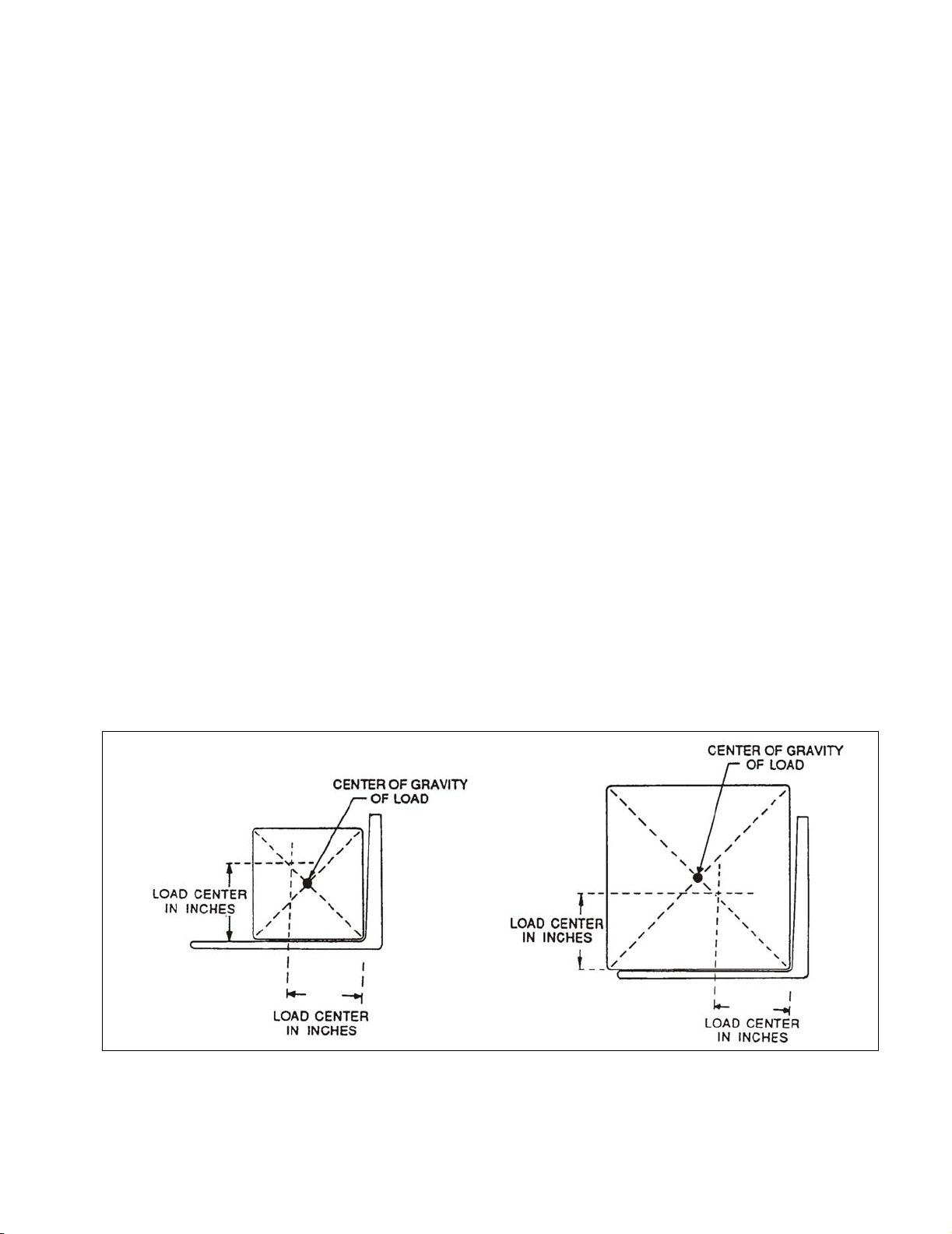
• Center and carry the load as far back as possible
toward the lift carriage back rest. The center-of-grav-
ity of the load must not exceed the load center listed
on the nameplate. See Figure 2-1 for load center
limitations.
• Pick up loads on both forks. Do not pick up on only
one fork.
• When traveling, always lower the load as far as pos-
sible.
Figure 2-1 Load Center
R3814

2-2 BG-S22-0812
• When stacking pallets in racks and it is necessary to
move the load in a raised position, use caution.
Operate truck smoothly.
• Observe applicable traffic regulations. Yield right of
way to pedestrians. Slow down and sound horn at
cross aisles and wherever vision is obstructed.
• Operate truck only from designated operation posi-
tion. Never place any part of your body between the
mast uprights. Do not carry passengers.
• Do not allow anyone to stand or pass under load or
lifting mechanism.
• When leaving truck, neutralize travel control. Fully
lower lifting mechanism and set brake. When leaving
truck unattended, turn off key switch, remove key
and disengage the emergency stop switch.
2-3. BEFORE OPERATION
Table 2-1 covers important inspection points on the
S22 lift truck which should be checked prior to opera-
tion. Depending on use, some trucks may require
additional checks.
Figure 2-2 shows a sample format for an Operator
Checklist, which can be modified as necessary to fit
your operation.
WARNING: Periodic maintenance of this truck by a
QUALIFIED TECHNICIAN is required.
CAUTION: A QUALIFIED SERVICE TECHNICIAN
should check the truck monthly for
proper lubrication, proper fluid levels,
brake maintenance, motor maintenance
and other areas specified in the SEC-
TION 3.
WARNING: If the truck is found to be unsafe and in
need of repair, or contributes to an
unsafe condition, report it immediately to
the designated authority. Do not operate
it until it has been restored to a safe
operating condition. Do not make any
unauthorized repairs or adjustments. All
service must be performed by a qualified
maintenance technician.
Table 2-1 Operator Checks
ITEM PROCEDURE
Transmission
and hydraulic
systems.
Check for signs of fluid leakage.
Forks Check for cracks and damage;
and, that they are properly
secured.
Chains, cables
and hoses
Check that they are in place,
secured correctly, functioning
properly and free of binding or
damage.
Guards and load
backrest
Check that safety guards are in
place, properly secured and not
damaged.
Safety signs Check that warning labels,
nameplate, etc., are in good
condition and legible.
Horn Check that horn sounds when
operated.
Steering Check for binding or looseness in
steering arm when steering.
Travel controls Check that speed controls on
control head operate in all
speed ranges in forward and
reverse and that belly button
switch functions.
Wheels Check drive wheel for cracks or
damage. Move truck to check
load for freedom of rotation.
Hydraulic
controls
Check operation of lift and lower
to their maximum positions.
Brakes Check that brakes actuate when
steering arm is raised to upright
position, and when lowered to
horizontal position.
Deadman/
Parking brake
Check that steering arm raises to
upright position when released
and brake applies.
Emergency Stop
Switch
Check that emergency stop
switch can be disengaged and
reengaged.
Battery charge Check the battery indicator.
High speed limit
switch
Allow for enough space to oper-
ate truck in high speed. Elevate
forks approximately two feet,
then test drive truck to check if
high speed is cut out.
ITEM PROCEDURE
BG-S22-0812 2-3
Figure 2-2 Sample of Operator Check List
R6479
Electric Truck
Daily Operator Check-Off List
Date
Big Joe Manufacturing Company
Operator
Truck No. Model No.
Dept.
Check
Tires
Load Wheels
Horn
Lift Lower Control
Need MaintenanceO.K. ( )
Shift
Hour Meter
Reading Drive Hoist
Attachment Operation
Forward & Reverse Controls
Steering
Brakes
Hydraulic Leaks, Cylinders,
Valves, Hoses, Etc.
2-4 BG-S22-0812
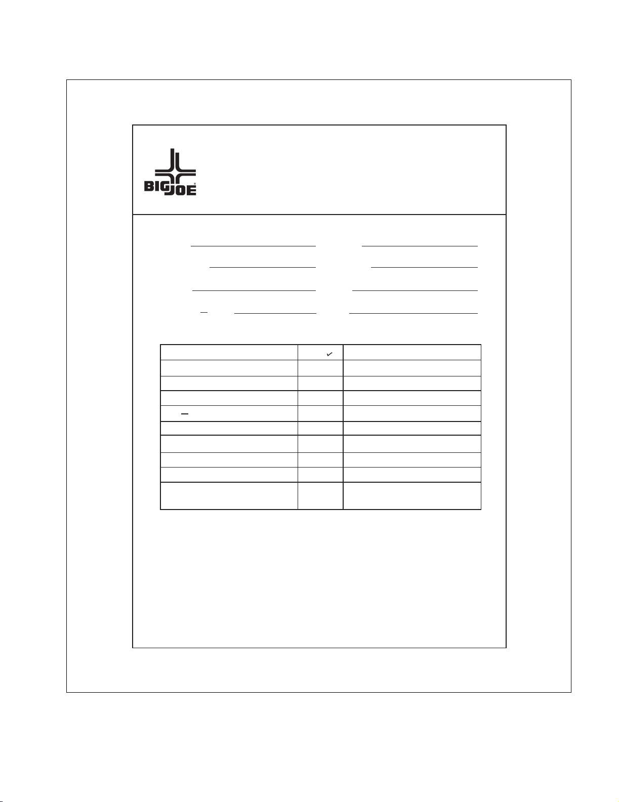
2-4. GENERAL CONTROL OPERATION.
The speed control (See Figure 2-3) located on each
side of the control head provides fingertip control for
driving the truck. Rotate the control in the direction you
want to travel. The farther you rotate the control from
the neutral position, the faster the truck will travel.
Figure 2-3 Forward/Reverse Control
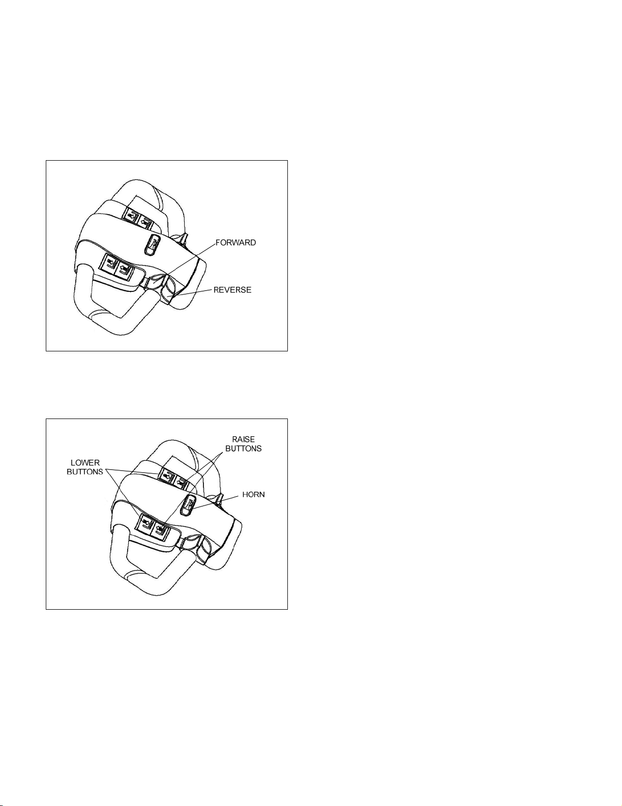
The pushbutton switches (See Figure 2-4), located on
the front of the control head activate the lift-lower con-
trols and the horn.
Figure 2-4 Pushbutton Switches
2-5. DRIVING AND STOPPING PROCEDURES.
1. Disengage the emergency stop switch and turn
on the key switch. Grasp the grips of the steering
head so that the speed control can be comfortably
operated by either thumb.
2. Lower the steering arm to a comfortable position
above horizontal to disengage the brake and to
energize the electrical circuits. If the truck is not
moved, the electrical circuits will time out and will
deenergize. See Figure 2-5.
3. To move forward (with load in back), slowly press
the speed control forward. See Figure 2-3. Press
the forward speed control farther to increase
speed.
4. To slow down or stop, release the speed control
and lower or raise the steering arm to the horizon-
tal or vertical position. See Figure 2-5. In those
positions, the brake engages, slowing or stopping
the truck.
5. Procedures for movement in reverse are the
same as in the forward direction except slowly
press the speed control backward. See Figure 2-
3.
2-5.1. Stopping
The brake pattern of the truck depends on the ground
conditions. The driver must take this into account
when operating the truck.
The driver must be looking ahead when traveling. If
there is no hazard, brake moderately to avoid moving
the load.
There are four different ways to stop the truck:
1. Plugging: This electrical braking function con-
sists of rotating the speed control lever in the
opposite direction of travel and then releasing it
when the truck stops. Plugging is a convenient
way to stop the truck during normal operation. If
the control is not released, the truck will acceler-
ate in the opposite direction.
2. Steering arm (See Figure 2-5): The brake is fully
applied by lowering or raising the steering arm.
(See Figure 2-5) All traction control power is shut
off when the brake is engaged. When the steering
arm is in the upright position, the brake acts as a
parking brake. Deadman braking occurs when the
handle is released and spring action raises steer-
ing arm to the upright position.
3. Emergency braking: Press the emergency brake
switch, all electrical functions are cut out and the
truck automatically brakes.
4. Regenerative braking: If the speed control lever
is released, the truck automatically brakes regen-
eratively. When the speed is below.5 MPH, the
brake applies.
R6617
R6618
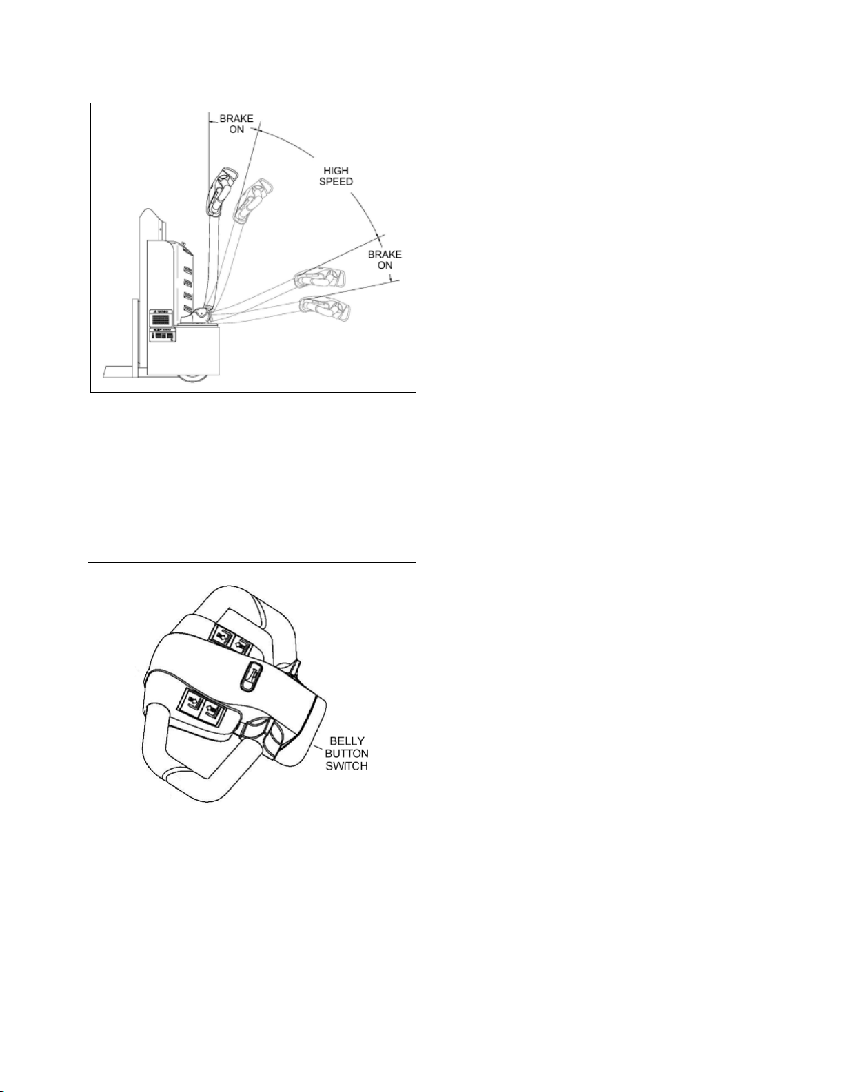
BG-S22-0812 2-5
Figure 2-5 Brake Actuation
2-6. BELLY-BUTTON SWITCH.
The belly-button switch (Figure 2-6) minimizes the
possibility of the driver being pinned by the steering
arm while driving the lift truck in slow speed. If the
switch presses against the operator while the lift truck
is being driven toward the operator, the switch
changes the direction of the lift truck.
Figure 2-6 Belly-Button Switch
2-7. STEERING ARM GAS SPRING.
The steering arm gas spring automatically raises the
steering arm to the upright position when the steering
arm is released. If the steering arm does not return
fully, the steering arm gas spring requires replace-
ment. Return truck to maintenance for repair.
2-8. LIFT AND LOWER CONTROLS.
Lift/Lower Control buttons are located on the steering
control head. (Figure 2-4)
To lift forks, push in either LIFT button and hold until
forks reach desired height. To lower forks, push in
either LOWER button and hold until forks descend to
desired height.
2-9. LOADING AND UNLOADING.
1. Move truck to location where load is to be picked
up.
2. Move the truck into position so forks are within
pallet or skid, and the load is centered over the
forks and as far back as possible.
3. Raise forks to lift load.
4. Drive to area where load is to be placed.
5. Move truck to align load with its new position.
6. Lower the load until it rests squarely in place and
the forks are free.
7. Slowly move the truck out from under the load.
2-10.PARKING.
When finished with moving loads, return the truck to its
maintenance or storage area. Turn off the key switch
and engage the emergency stop switch. Charge bat-
teries as necessary. Refer to battery care instructions,
SECTION 3.
R6772
R6619

2-6 BG-S22-0812
NOTES

BG-S22-0812 3-1
SECTION 3
PLANNED MAINTENANCE
3-1. GENERAL.
Planned maintenance consists of periodic visual and
operational checks, parts inspection, lubrication, and
scheduled maintenance designed to prevent or dis-
cover malfunctions and defective parts. The operator
performs the checks in SECTION 2, and refers any
required servicing to a qualified maintenance techni-
cian who performs the scheduled maintenance and
any required servicing.
3-2. MONTHLY AND QUARTERLY CHECKS.
Table 3-1 is a monthly and quarterly inspection and
service chart based on normal usage of equipment
eight hours per day, five days per week. If the lift truck
is used in excess of forty hours per week, the fre-
quency of inspection and service should be increased
accordingly. These procedures must be performed by
a qualified service technician or your Big Lift LLC Ser-
vice Representative.
3-3. BATTERY CARE.
3-3.1. General
The S22 may be equipped with maintenance free bat-
teries.
The care and maintenance of the battery is very
important to obtain efficient truck operation and maxi-
mum battery life.
CAUTION: Gases produced by a battery can be
explosive. Do not smoke, use an open
flame, create an arc or sparks in the
vicinity of the battery. Ventilate an
enclosed area well when charging.
CAUTION: Batteries contain sulfuric acid which may
cause severe burns. Avoid contact with
eyes, skin or clothing. In case of contact,
flush immediately and thoroughly with
clean water. Obtain medical attention
when eyes are affected. A baking soda
solution (one pound to one gallon of
water) applied to spilled acid until bub-
bling stops, neutralizes the acid for safe
handing and disposal.
Leakage voltage from battery terminals to battery case
can cause misleading trouble symptoms with the truck
electrical system. Since components of the truck elec-
trical system are insulated from truck frame, leakage
voltage will not normally affect truck operation unless a
short circuit or breakdown of circuit wire insulation to
truck frame occurs.
A voltage check from battery connector terminal to
battery case should indicate near zero volts. Typically,
however, the sum of the voltages at both terminals will
equal battery volts. This leakage voltage will discharge
the battery. As battery cleanliness deteriorates, the
usable charge of the battery decreases due to this self
discharge.
Table 3-1 Monthly and Quarterly Inspection and Service Chart
VISUAL CHECKS
INTERVAL INSPECTION OR SERVICE
Monthly Check electrical brake for proper operation.
Monthly Check load wheels for wear. A poly load wheel must be replaced if worn to within 1/16 inch
of hub. Check for separation from hub.
Monthly Check drive wheel for wear. A poly drive wheel must be replaced if worn to within 3/4 inch
of hub. Check for separation from hub.
Monthly Inspect wiring for loose connections and damaged insulation.
Monthly Check deadman brake switch for proper operation.
Monthly Check lift chain tension, lubrication & operation (see paragraph 3-7.)
Quarterly Check lift cylinder for leakage.
Quarterly Check for excessive jerking of steering arm when stopping or starting.
Semi-annually Inspect for chain wear (See SECTION 8)

3-2 BG-S22-0812
Although a leakage voltage reading of zero volts may
not be possible, a cleaner battery will have more
usable charge for truck operation and not affect opera-
tion of electronic devices on the unit.
3-3.2. Safety Rules
• Wear protective clothing, such as rubber apron,
gloves, boots and goggles when performing any
maintenance on batteries. Do not allow electrolyte to
come in contact with eyes, skin, clothing or floor. If
electrolyte comes in contact with eyes, flush immedi-
ately and thoroughly with clean water. Obtain medi-
cal attention immediately. Should electrolyte be
spilled on skin, rinse promptly with clean water and
wash with soap. A baking soda solution (one pound
to one gallon of water) will neutralize acid spilled on
clothing, floor or any other surface. Apply solution
until bubbing stops and rinse with clean water.
• Do not bring any type of flame, spark, etc., near the
battery. Gas formed while the battery is charging, is
highly explosive. This gas remains in cell long after
charging has stopped.
• Do not lay metallic or conductive objects on battery.
Arcing will result.
• Do not touch non-insulated parts of DC output con-
nector or battery terminals to avoid possible electri-
cal shock.
• De-energize all AC and DC power connections
before servicing battery.
• Do not charge a frozen battery.
• Do not use charger if it has been dropped or other-
wise damaged.
3-3.3. Battery Care and Charging
CAUTION: Never smoke or bring open flame near
the battery. Gas formed during charging
is highly explosive and can cause seri-
ous injury.
1. Charge the battery only in areas designated for
that use.
2. Battery terminals should be checked and cleaned
of corrosion regularly. Good battery terminal con-
tact is essential not only for operation, but also for
proper charging of the battery.
3. The charging requirements will vary depending on
the use of the truck. The battery should be given
as equalizing charge on a weekly basis. This
charge should normally be an additional three
hours at the finish rate.
4. Make certain battery used meets weight and size
requirements of truck. NEVER operate truck with
an undersized battery.
3-3.4. Battery Cleaning
Always keep vent plugs tightly in place when cleaning
battery. When properly watered and charged, the bat-
tery will remain clean and dry. All that is necessary is
to brush or blow off any dust or dirt that may accumu-
late on them. However, if electrolyte is spilled or over-
flows from a cell, it should be neutralized with a
solution of baking soda and water, brushing the soda
solution beneath the connectors and removing grime
from the covers. Then rinse the battery with cool water
from a low pressure supply to remove the soda and
loosen dirt. If batteries stay wet consistently, they may
be either overcharged or over filled. This condition
should be investigated and corrected.
3-3.5. MAINTENANCE FREE BATTERIES
Some trucks may be equipped with maintenance free
batteries. These batteries are completely sealed, will
not require any watering and have a full 80% dis-
charge available.
Sealed Maintenance Free batteries contain a pressure
release valve and under normal operating conditions
do not require any special ventilation.
CAUTION: Do not try to open this battery or remove
the pressure release valve.
Only under severe overcharging, such as connected
to an improperly sized charger, will any significant
amount of gasses be released from the battery. Also,
being a valve regulated battery, it never requires
watering.
BG-S22-0812 3-3
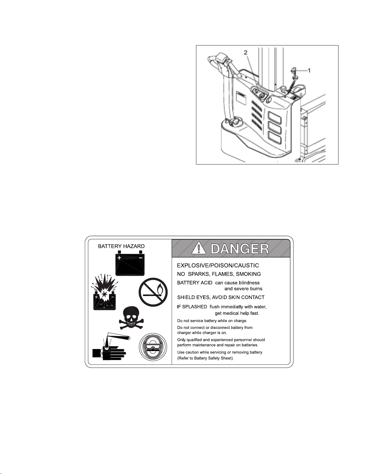
3-4. CHARGING BATTERIES
Charging requirements will vary depending on depth
of discharge and temperature. Follow safety rules
when placing a battery on charge.
Proceed as follows:
1. Park truck at charging station with carriage low-
ered and turn the key switch off.
2. Check the condition of the AC cord and battery
cables. If there are any cuts in the cable, any
exposed wires, loose plugs or connectors, DO
NOT attempt to charge the batteries. Contact
appropriate personnel for repairs to be made.
3. Pull the charger cord out of the cover (1, Figure 3-
1) and connect to the appropriate power supply,
4. The LED (2) flashes red to indicate that the
charger is connected.
5. Charge the batteries until the LED (2) produces a
permanent green light.
6. Disconnect the charger cord and insert it in its
receptacle on the truck.
Figure 3-1 Battery Charging
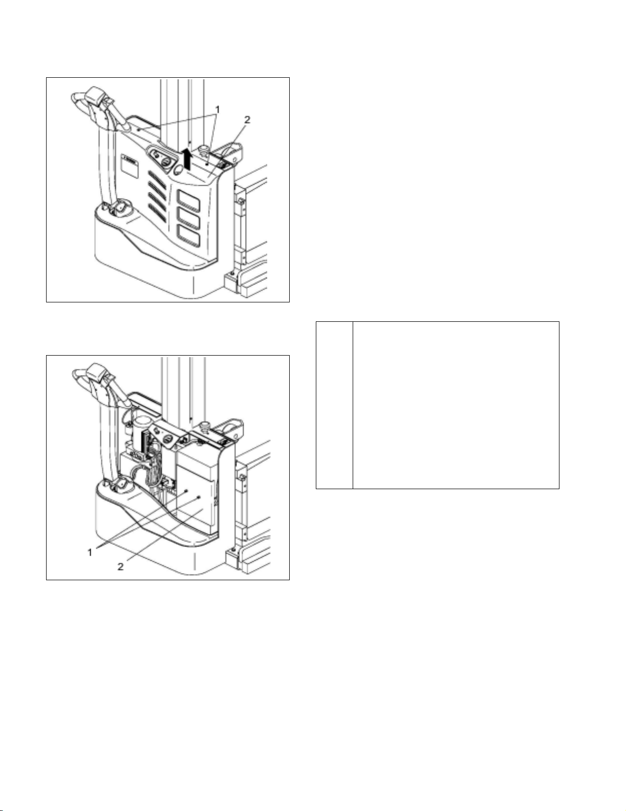
3-5. CHARGING BATTERIES
1. Park truck at charging station with carriage low-
ered and turn the key switch off and engage the
emergency stop switch.
2. Remove two screws (1, Figure 3-2) and remove
cover (2).
R6873
3-4 BG-S22-0812
Figure 3-2 Battery Charging
3. Remove two screw (1, Figure 3-3) and remove
bracket (2).
Figure 3-3 Battery Charging
4. Tag and disconnect the three cables from the bat-
teries and replace the batteries.
5. Install in the reverse order of removal.
3-6. LUBRICATION.
Refer to Table 3-2 for the recommended types of
grease and oil. Table 3-3 in conjunction with
Figure 3-4 identifies the items requiring lubrication.
3-7. LIFT CHAIN MAINTENANCE.
Fully raise and lower lift carriage while observing
chains as they move over chain sheaves. Ensure
chain is aligned and tracking properly and all links are
pivoting freely. With lift carriage fully lowered, spray or
brush on a film of SAE 30 or 40 engine oil.
Table 3-2 Recommended Lubricants
(See Table 3-3 for Application)
R6874
R6875
No. 1 Transmission oil—EP SAE 80W-90
Transmission oil—EP SAE 10W-30 (Note)
No. 2 Grease—Lithium base, general purpose.
No. 3 Hydraulic oil-Heavy duty with a viscosity of
150 SUS foam suppressing agent and
rust and oxidation inhibitors
Hydraulic oil-Heavy duty with a viscosity of
100 SUS foam suppressing agent and
rust and oxidation inhibitors (Note)
No. 4 SAE 30 or 40 Engine lubricating oil
NOTE: USED ON COLD CONDITIONED TRUCKS
BG-S22-0812 3-5
Figure 3-4 Lubrication Diagram
Table 3-3 Lubrication Chart
FIG 3-2
INDEX
NO.
LOCATION METHOD OF
APPLICATION
TYPE
(Table
3-3)
APPLICATION
OF
LUBRICANT
1 Inner & Outer Mast Brush No. 2 Full length of channel where rollers
operate.
2 Lift Chain Brush or Spray No. 4 See Paragraph 3-7.
3 Lift Carriage Brush No. 2 Light coating where forks slide.
4Transmission
Capacity 2 pints
Can No. 1 Fill to level plug.
5 Hydraulic Reservoir
Capacity-1 quarts
Can No. 3 With lift carriage fully lowered, fill
reservoir with hydraulic oil to
level on breather dip stick.
R6871

3-6 BG-S22-0812
NOTES

BG-S22-0812 4-1
SECTION 4
TROUBLESHOOTING
4-1. GENERAL
Use Table 4-1 as a guide to determine possible
causes of trouble. The table is divided into five main
categories: Truck and Hydraulic System Will Not
Operate: Truck Does Not Operate Forward or
Reverse: Trouble With Braking: Trouble With Lifting Or
Lowering, and Miscellaneous malfunctions.
Table 4-1 Troubleshooting Chart
MALFUNCTION PROBABLE CAUSE CORRECTIVE ACTION
TRUCK AND HYDRAULIC
SYSTEM WILL NOT OPERATE
Truck will not travel not will lift sys-
tem operate.
a. Fuse (2, Figure 12-24 or
Figure 12-24) blown.
Check fuse and replace if
necessary.
b. Fuse (28, Figure 12-22 or
17, Figure 12-23) blown.
Check fuse and replace if
necessary.
c. Battery dead or disconnected. Check battery connections and
check battery voltage.
d. Keyswitch (4, Figure 12-22 or
3, Figure 12-23) defective.
Bypass keyswitch to determine if it
is malfunctioning.
e. Emergency stop switch (31,
Figure 12-22 or
28, Figure 12-23) defective.
Bypass keyswitch to determine if it
is malfunctioning.
f. Defective wiring. Check for open circuit. Repair as
required.
TRUCK DOES NOT OPERATE
FORWARD OR REVERSE
Truck does not travel forward or
reverse. All other functions oper-
ate normally.
a. Check all wiring. A loose con-
nection may be the cause of
malfunction.
Tighten all loose connections
before further troubleshooting.
b. Defective deadman switch (16,
Figure 12-1).
Check and replace switch if
defective.
c. Defective controller (13, Figure
12-22 or 9, Figure 12-23).
Check for proper operation and
replace if necessary.
d. Defective potentiometer (15,
Figure 12-2).
Check and replace potentiometer
if defective.
Truck travels forward but not in
reverse.
Defective potentiometer (15, Fig-
ure 12-2) in control head.
Check and replace potentiometer
if defective.
Truck travels reverse but not in
forward.
Defective potentiometer (15, Fig-
ure 12-2) in control head.
Check and replace potentiometer
if defective.
Truck travels forward and in
reverse at lower speeds; will not
travel at high speed.
Defective potentiometer (15, Fig-
ure 12-2) in control head.
Check and replace potentiometer
if defective.

4-2 BG-S22-0812
Table 4-1 Troubleshooting Chart - Continued
MALFUNCTION PROBABLE CAUSE CORRECTIVE ACTION
TROUBLE WITH BRAKING
Truck does not slow with brake, or
brake does not engage.
a. Defective deadman switch (16,
Figure 12-1).
Check deadman switch for
continuity. If none found when
the control arm is in the brake
position, replace switch.
b. Defective electric brake (1, Fig-
ure 12-5).
Adjust or replace brake.
Brake will not release. a. Air gap more than 0.01 in
(0.25mm).
Adjust.
b. Brake temperature above
281° F (140°C).
Allow to cool and check air gap.
c. Open brake circuitry or wiring. Make voltage checks.
Brake drags. Defective electric brake (1, Figure
12-5).
Replace.
Brake grabs. a. Incorrect stopping distance
adjustment.
Adjust.
b. Defective electric brake (1, Fig-
ure 12-5).
Replace.
Abnormal noise and chatter when
brake is applied.
Defective electric brake (1, Figure
12-5).
Replace.
TROUBLE WITH LIFTING OR
LOWERING
Oil sprays or flows from the top of
the lift cylinder.
Defective packing in lift cylinder Repair lift cylinder.
Squealing sounds when lifting
forks.
a. Oil level too low. Identify oil leak and fill reservoir.
b. Dry channels in mast. Apply grease.
c. Defective mast or carriage roll-
ers
Replace rollers.
Forks do not lift to top. a. Oil level too low. Add oil to reservoir.
b. Load larger than capacity. Refer to I.D.plate for capacity.
Weak, slow or uneven action of
hydraulic system.
a. Defective pump or relief valve. Check pressure. Adjust as
necessary.
b. Worn lift cylinder. Replace cylinder.
c. Load larger than capacity. Refer to I.D.platefor capacity.
d. Defective lift motor solenoid. Replace solenoid (2, Figure 12-
19) on pump motor.
e. Battery charge low. Charge battery.
Forks do not lift, pump motor does
not run.
a. Battery is dead or discon-
nected.
Check and recharge if required.
b. Defective wiring. Check and repair as required.
c. Defect in electrical system for
operating pump motor.
Check lift switch in control head,
as well as the solenoid (2, Figure
12-19).
Table of contents
Other Blue Giant Truck manuals


