Blue Giant BG2-72 User manual
OPERATOR’S MANUAL
BG2-72 LOW LEVEL ORDER PICKER
ISSUE DATE: March, 2020 REV.0 (PART # 038-xxxE)
WARNING
Do not operate or service this product unless you have read and fully
understand the entire contents of this manual. Failure to do so may result in
property damage, bodily injury or death.
ACTUAL PRODUCT MAY NOT APPEAR EXACTLY AS SHOWN

A
WARNING
Do not operate this truck unless you have been authorized and trained to do so, and have
read all warnings and instructions in Operator's Manual and on this truck.
Do not operate this truck until you have checked its condition. Give special attention to
tires, horn, lights, battery, controller, lift system (including forks or attachments, chains,
cables and limit switches), brakes, steering mechanism, guards and safety devices.
Operate truck only from designated operating position. Never place any part of your body
into the mast stru cture, between the mast and the truck, or outside the Operator's platform.
Be sure any operator personal safety systems (guardrails, safety belts, harnesses, lifelines ,
etc.) are in place, properly worn and connected . Utilize additional protective fall restraint
equipment as applicable.
Observe appllcable traffic regulations. Do not carry passengers. Yleld right of
way
to pedestrians.
Slow down and sound horn at cross aisles and wherever vision is obstructed.
Start, stop, travel, steer and brake smoothly. Slow down for turns and on uneven or slippery
surfaces that could cause truck to slide or overtu rn.
Use special care when traveling without load as the risk of overturn may be greater.
Travel with lifting mechanism as low as possible. Always look in direction of travel and
keep a clear view.
Use special care when operating on ramps - travel slowly, and do not angle or turn.
Travel with lifting mechanism uphill.
Do not overload truck. Check nameplate for capacity and load center information .
Before lifting, be sure load is centered, forks are completely under load, and load is as far
back toward operator's platform as possible.
Do not handle unstable or loosely stacked loads. Use special care when handling long,
high or wide loads, to avoid losing the load, striking bystanders, or tipping the truck.
Do not handle loads when top of tiered load is more than 120 inches above the ground.
Ensure there is proper protection against falling objects from adjacent high stack areas.
Elevate forks or other lifting mechanism only to pick up or stack a load.
Watch out for obstructions, especially overhead.
Do not lift other personnel. Never transport personnel on forks.
Do not allow anyone to stand or pass under load or lifting mechanism.
When leaving truck, neutralize travel control, fully lower lifting mechanism and set brake.
When leaving truck unattended , also shut off power.
PROPOSITION 65
WARNING
1n accordance to
California Health & Safety Code Sections 25249.5 et. seq.
this warning is to let you know that this product can expose
yo u to chemicals known to the state of California to
cause cancer, birth defects and other reproduct ive harm .
For more information visit : www.p65warn ings.ca.g ov

FOREWORD
As a lift truck operator, you are
responsible for a machine that is
useful, powerful, and can be
hazardous if not operated as
described. Your Blue Giant truck
may weigh more than some cars,
depending on the model. Observing
and practicing the safety warnings
in this manual cannot be
overemphasized. Just knowing the
warnings, however, is no substitute
for common sense. Focusing on the
task at hand will, in almost all cases,
prevent accidents. Think of the truck
as your own. In this way you will learn
its capabilities and limitations.
This manual is intended to
remain with the truck at all times as a
handy
reference guide to operation. Detailed
maintenance procedures are found in
the parts and service manual for the
specific truck model, and aretobe
performed only bya qualified
technician. For further
information on obtaining a
complete parts and service manual,
see page 20 of this manual.
The operator who knows his truck will
learn to spot problems as they
develop. This is accomplished by
performing the Daily Checks and
reporting any problems to the
designated authority.
TABLE OF CONTENTS
SAFETY SYMBOLS .....................................................................
GENERAL DESCRIPTION............................................................ 2
LOAD CAPACITY ............................................................................. 4
BEFORE OPERATION ..................................................................... 5
Operator Checks ............................................................. 6
CONTROLS................................................................................... 7
INSTRUMENT PANEL...................................................................... 9
OPERATION.................................................................................. 11
Driving Procedures. ........................................................ 11
Stopping Procedures...................................................... 12
Picking Up A Load. ......................................................... 12
Transporting Loads......................................................... 12
Placing Loads.................................................................. 13
Overhead Maintenance................................................... 13
Parking. ............................................................................ 13
Moving A Disabled truck ................................................ 13
NOTICE - OBTAINING A PARTS AND SERVICE MANUAL ....... 20

2
SAFETY SYMBOLS
WARNING and CAUTION are both signal words intended to alert the viewer to
the existence and relative degree of a hazard. They are both preceded by a safety
alert symbol consisting of an exclamation mark enclosed by a triangle.
A Warning indicates a hazard which could result in injury or death if proper
precautions are not taken.
A Caution indicates a reminder of routine safety practices.
A prohibition slash (circle with diagonal slash through it) indicates a procedure or
action that should not be performed under any circumstances, as both personal
injury and/or damage to equipment will result.
GENERAL DESCRIPTION
The self-propelled lifts and
transports the operator (on the
platform portion of the lift carriage)
and the payload (on forks or optional
payload platform). This permits
efficient selection and moving of
materials in any area or at any level
of the warehouse or storeroom.The
design permits one man to perform
all operations of selecting the
stock, driving the truck, and replacing
the stock at the designated place.
The battery-powered truck is quiet
and without exhaust fumes,
allowing operation in closed areas
without special provisions for
ventilation.
The truck can be driven with the
platform raised or lowered; however
the speed is restricted above 15”.
On demand power steering makes the
truck highly maneuverable.
The control arms are used to operate
the work truck and provide operator
safety.
The operator platform contains the
deadman foot switch which must be
depressed for the truck to operate.
The model number will be found on
the name plate along with the serial
number, lifting capacity, and load
center.
Name Plate

3
WARNING:
This truck is equipped with a battery. Read and heed the warning decal located
near the battery. An example is shown here:
4
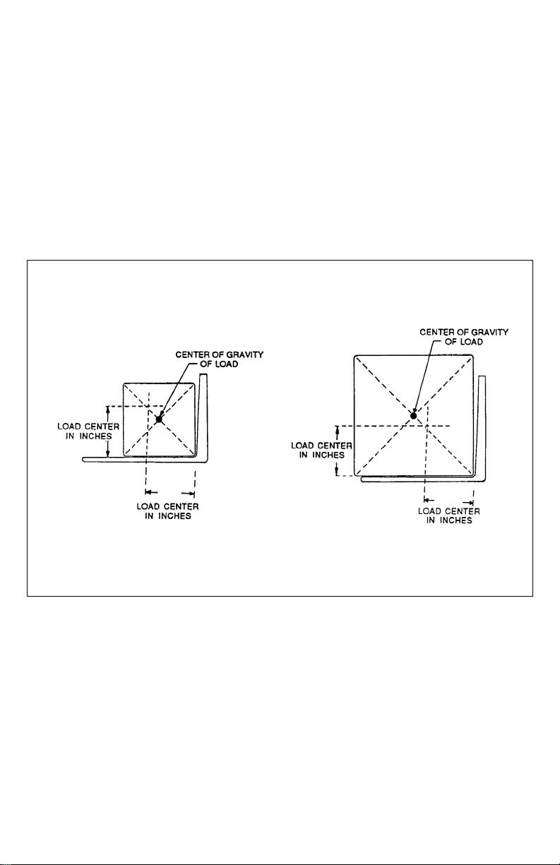
LOAD CAPACITY
Do not overload truck. Check name
plate for load weight capacity and load
center information.
The load capacity depends on the
load center. The load maximum
capacity listed on the capacity plate
assumes a uniform load whose center
is at 1/2 the length of the fork and
centered between the forks. The
maximum load capacity isreduced
when
the load center exceeds 1/2 the length
of the forks or is not centered between
the forks. The fork length and wheel
base must be adequate for the skid or
bin to be handled.
Note that a truck in motion is less
stable than a standing truck. Ifyou
are not sure that the truck can lift a
certain load, consult your supervisor
or the designated authority.
Load Center
R3814

5
R6235
BEFORE OPERATION
The table on page 6 covers important
inspection points on trucks which
should be checked prior to operation.
Depending on use, some trucks may
require additional checks.
The illustration below shows a sample
format for an Operator Checklist, which
can be modified as necessary to fit your
operation.
WARNING:
Periodic maintenance of this
truck by a QUALIFIED SERVICE
TECHNICIAN is required.
WARNING:
A QUALIFIED SERVICE TECHNICIAN
should check the truck
monthly for proper lubrication,
proper fluid levels, brake
maintenance, motor
maintenance and other areas
specified in the parts and
service manual maintenance
section.
WARNING:
If the truck isfound tobeunsafe
and inneed ofrepair, or
contributes to an unsafe
condition, report it immediately
to the designated authority. Do
not operate it until it has been
restored to a safe operating
condition. Do not make any
unauthorized repairs or
adjustments. All service must be
performed bya qualified service
technician.
Electric Truck
Daily Operator Check-Off List
Date Operator
Tru ck No. Model No.
Dept. Shift
Reading Dr i ve Hoist
Sample of Operator Check List
Check
O.K. ( )
Need Maintenanc e
Tir es
Load Wheels
Horn
Lift Lower Control
Attachment Operation
Forward & Rev erse Control s
Steering
Electrical Brakes
Hydraulic Leaks, Cylinders,
Valves, Hos es, Etc.

6
Operator Checks
ITEM
PROCEDURE
Transmission and hydraulic
systems
Check for signs of fluid leakage.
Forks and rear tray
Check for cracks and damage; that they are
properly secured.
Chains, cables and hoses
Check that they are in place, secured
correctly, functioning properly and free of
binding or damage.
Control arms and guard rails
Check that truck operation is disabled when
arms and guard rails are raised.
Safety warning label and
nameplate
Check that warning labels, nameplate, etc.,
are in good condition and legible.
Horn and flashing lights
Check that horn sounds when operated and
flashing lights are operable.
Steering
Check for binding or looseness when steering.
Travel controls
Check that travel control on right control arm
operates in all speed ranges in forward and
reverse.
Wheels
Check drive wheel for cracks or damage.
Move truck to check load wheel for freedom of
rotation.
Hydraulic controls
Check operation of lift and lower to their
maximum positions.
Emergency power discon-
nect switch
Check that brake actuates when emergency
power disconnect switch is depressed.
Battery disconnect
Check that battery can be disconnected and
reconnected. Check for connector damage.
Speed limit switches
Allow for enough space to operate truck in all
speeds. Test drive the truck to check for speed
reductions when elevated.
Platform Operation
Check that allcontrols in the platform
operating compartment are operational.
7
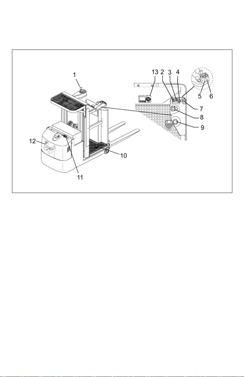
CONTROLS
Refer to the following illustration for
the location of the controls.
Controls
STEERING CONTROL (1)
This control is operated in the
conventional manner. Drive wheel
direction is also indicated on the
instrument panel.
OPERATOR PLATFORM LIFT (2)
To raise the operator platform, push
and hold this button until the desired
height is reached. Guard rails need to
be in the lowered position and
deadman footswitch needs to be
engaged for travel and lift.
OPERATOR PLATFORM LOWER
(3)
To lower the operator platform, push
and hold this button until the desired
height is reached. Guard rails need to
be in the lowered position and
deadman footswitch needs to be
engaged for travel and lift.
HORN BUTTON (4)
Sounds the horn.

8
FORK LOWER BUTTON (5)
To lower the forks, push and hold this
button until the desired height is
reached. Guard rails need to be in the
lowered position and deadman
footswitch needs to be engaged for
travel and lift.
FORK LIFT BUTTON (6)
To lift the forks, push and hold this
button until the desired height is
reached. Guard rails need to be in the
lowered position and deadman
footswitch needs to be engaged for
travel and lift.
KEY SWITCH (7)
The key switch has two positions,
ON and OFF. Remove the key to
prevent unauthorized use.
TRAVEL SWITCH (8)
This switch controls forward, neutral
and reverse travel. Travel direction is
also indicated on the instrument
panel.
EMERGENCY POWER
DISCONNECT SWITCH (9)
Pushing down the emergency power
disconnect switch disconnects the
main power, deactivates all electrical
functions, causing the truck to brake
automatically.
DEADMAN SWITCH PEDAL (10)
Operator must stand on this pedal to
activate the controls.
BATTERY DISCONNECT (11)
The battery disconnect can beused to
cut off all power to the truck. It is also
used to connect the batteries to the
battery charger.
EMERGENCY LOWERING BUTTON
(12)
Press this button to lower the platform
in case of an emergency.
INSTRUMENT PANEL (13)
The instrument panelcontains the
following displays and controls:

9
INSTRUMENT PANEL
LOW BATTERY ALARM LED (1)
This LED lights when the measured
battery voltage is equal or less than
40% normal battery voltage.
FAULT ALARM LED (2)
When a fault is detected, this LED will
light. The display (7) will display the
warning and fault indication. Report
alarm to the designated authority and
do not use the truck until corrected by
a qualified mechanic.
TEMPERATURE ALARM LED (3)
When the temperature of the motor/
controller exceeds allowable range
(too high or low), the LED will
illuminater. Temporarily stop operation
until the temperature drops and
notify an authorized technician.
DEADMAN SWITCH ALARM LED
(4)
When the deadman switch pedal is
released, this LED will illuminate.
BRAKE ALARM (5)
This LED will illuminate when the
brake is applied.
FUNCTIONAL KEYS (6)
Use the left arrow button to adjust the
speed mode. Use the down arrow
button to switch the driving mode.
DISPLAY (7)
The display has the following
functions:

10
Driving Mode Display (4): The
truck can be operated in two driving
modes, high sped or crawl speed.
High Speed
Creep Speed
Display
Battery Indicator (1): The state of
charge is displayed by ten notches.
Each notch represents 10% of the
battery charge. For example, the
illustration shows the battery has
80% charge.
Information Display (2): Displays the
warnings and faults. Report warnings
and faults to the designated authority
and do not use the truck until
corrected by a qualified mechanic.
Speed Display (3): Indicates the
truck’s speed.
Speed Mode Display (5): There are
four speed ranges available in both
high speed driving mode and the
creep speed driving mode. Use the
“left function key to select the desired
mode. “1” indicates the slowest speed
while “4” indicates the highest speed.
CAUTION:
When the platform rises the
truck automatically enters crawl
speed.
Steering Display (6): One of nine
notches will indicate the steering
angle of the drive wheel.

11
OPERATION
Operation
DRIVING PROCEDURES.
The truck can be driven with the platform
raised or lowered; however, the speed is
restricted when the platform
is raised above a preset limit of 15”.
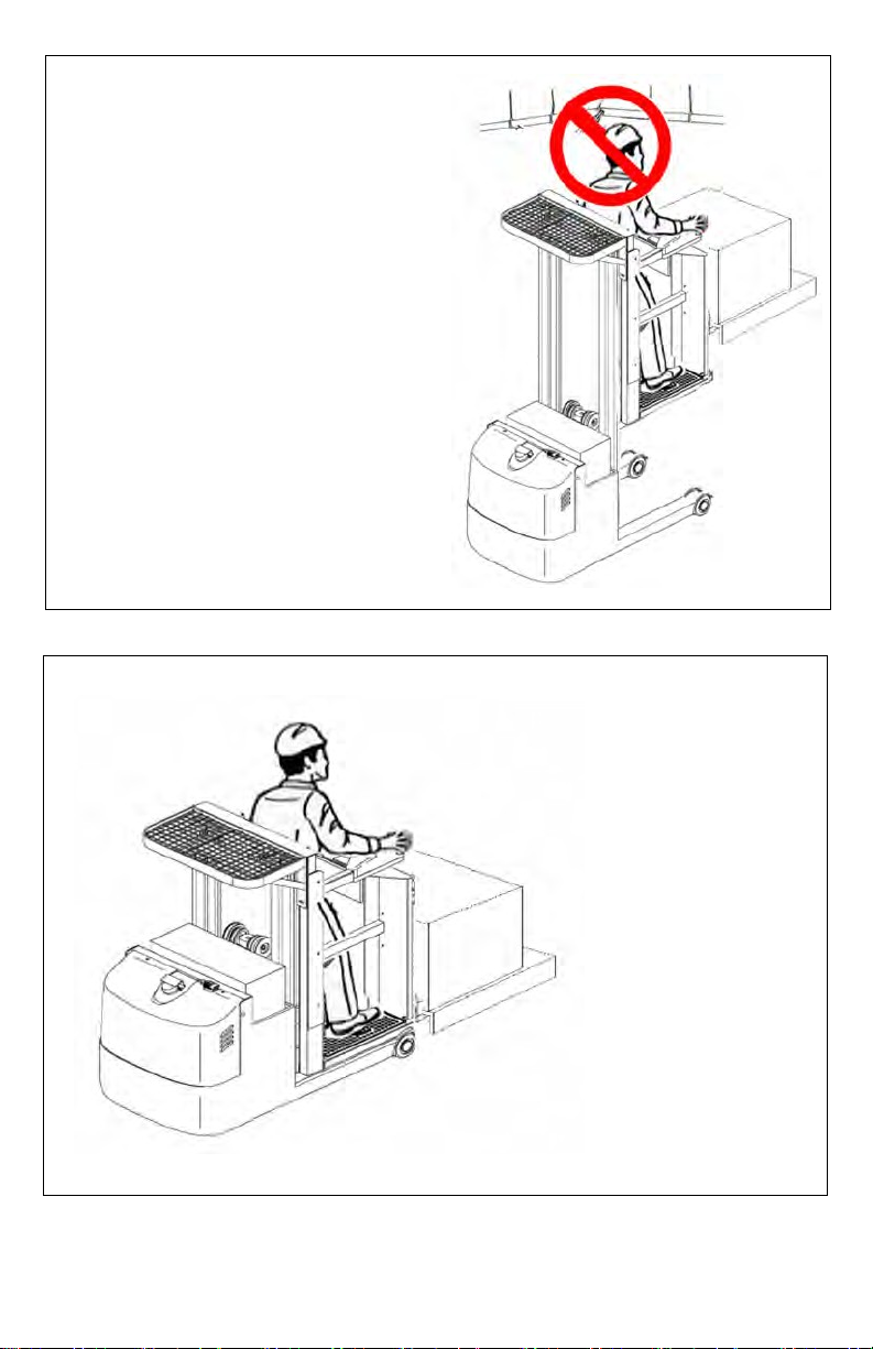
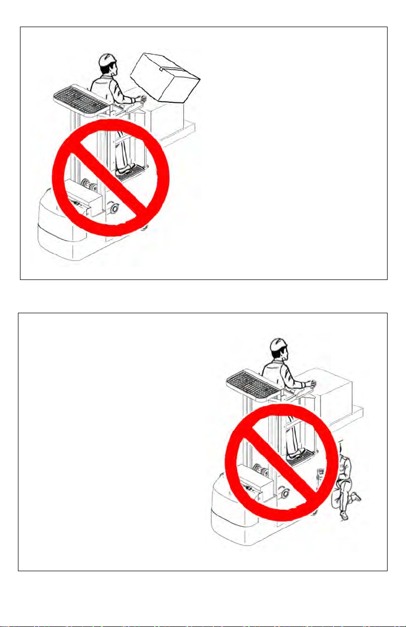
WARNING:
Do not leave the platform while
the operator platform is
elevated. Do not lean out from
the outside of a cage rail.
Climbing on the guard rails
and/or forks is strictly
prohibited and can lead to
severe injury or death.
WARNING:
Only one person is permitted in
the operator’s compartment at
all times.
Proceed as follows to start and stop
the truck.
1.
Step on the operator platform with
your backagainst the back rest.
2.
Lower the control arms and guard
rails.
3.
Turn on the keyswitch (7) and pull
up on the emergency power
disconnect switch (9).

12
4.
Step on the deadman footswitch
(10) to activate the electrical
controls.
5.
Select the speed mode using the
“left” function key on the
instrument panel (13).
6.
Using the steering control (1) to
steer the truck in the required
direction. Drive wheel directions is
indicated on the instrument panel.
7.
Using your right hand, move the
travel switch (8) to the desired
direction.
NOTE: The truck direction may be
reversed while moving. The
control will cycle the motor to
stop and then reverse in a
timed sequence without
danger to the equipment.
Exercise caution when doing
so, especially when
traveling at maximum speed.
Emergency Braking: To stop rapidly
when an emergency exists, press the
emergency power disconnect switch
(9).
WARNING: WARNING:
The truck is equipped with a
level sensor. When the truck is
elevated and on a slope greater
than 0.5 degrees, the level
sensor sounds an alarm
beeper. The truck is only to
be used indoors on a level
surface. This truck is not for
use on mezzannes or balcony
areas.
STOPPING PROCEDURES.
The brake pattern of the truck depends
largely on the ground conditions. The
driver must take this into account when
operating the truck. The driver must be
looking ahead when traveling. If there is
no hazard, brake moderately to avoid
moving the load.
The truck can brake in three different
ways:
Coasting Brake: release the
deadman switch pedal (10) and allow
the truck to coast to a stop.
Plugging: To stop faster, slowly move
the travel switch (8) to the opposite
direction.
Except in an emergency, do not
stop suddenly.
PICKING UP A LOAD.
The operator platform lift is used to
raise the platform to desired height for
picking the load. The fork lift is used to
adjust the load height to a comfortable
operator height.
1.
Drive the truck carefully up to the
storage location.
2.
Press and hold lift button (2) until
the platform reaches the desired
height.
3.
Adjust the forks to a comfortable
operator height using fork buttons
(5 and 6).
4.
Move the load from storage
location to the forks or rear tray.
5.
Press and hold lower button (3)
until the platform is completely
lowered.
TRANSPORTING LOADS.
1.
Always transport load with the
platform completely lowered.

13
2.
Always transport loads on the
forks or the rear tray.
3.
Always be prepared to brake.
Only stop suddenly in emergency
situations.
4.
Reduce speed intight areas.
PLACING LOADS.
1.
Drive the truck carefully to the
storage location.
2.
Press and hold lift button (2) until
the platform reaches the desired
height.
3.
Press and hold lift button (6) to
raise the load to a comfortable
operator height.
WARNING:
Ensure storage location is suit-
able for storing the load (size
and capacity).
4.
Move the load from the forks or
rear tray to the storage location.
5.
Press and hold lower button (3)
until the platform is completely
lowered.
OVERHEAD MAINTENANCE.
When performing overhead
maintenance, please ensure there
are no obstacles, beams or other
obstructions
before elevating lift. Always fully
lower the platform before moving to
the next maintenance position.
Ensure a safe workenvironment
before proceeding with maintenance
and never operate the truck outside.
PARKING.
When leaving the truck, it must be
securely parked even for a short time.
1.
Park the truck in its designated
parking area.
WARNING:
Do not park the truck on a
slope. The forks and platform
must be completely lowered.
2.
Lower the forks and platform
completely.
3.
Set the emergency power
disconnect switch (9) to apply the
brake.
4.
Turn keyswitch (7) to off position.
Remove the key for added
security.
5.
Pull out battery disconnect (11).
MOVING A DISABLED TRUCK
Do not attempt to move a disabled
truck; notify your supervisor or proper
authority.

14
The following operating instructions appear on the truck warning decal, which is
located on the operator platform.
Do not operate this truck
unless you have been
authorized and trained to
do so, and have read all
warnings and instructions
contained in this operator’s
manual and on this truck.
Read, understand and
comply with the information
on the truck’s nameplate
at all times.
Do not operate this truck until
you have checked it’s condition.
Give special attention to tires,
horn, lights, battery, controller,
lift system (including forks or
attachments, chains, cables and
limit switches), brakes, steering
mechanism, guards and safety
devices.
If you have any questions, notify
your supervisor or proper
authority

15
Operate truck only from
designated operating position.
Never place any part of your
body into the mast structure,
between the mast and the truck,
or outside the Operator's
platform.
Observe applicable traffic
regulations. Do not carry
passengers Yield right of
way to pedestrians.
slow down and sound
horn at cross aisles and
wherever vision is
obstructed.

16
Travel with lifting mechanism as
low as possible. Always look in
direction oftravel & keep a
clear view.
Do not handle unstable or loosely stacked
loads. Use special care when handling
long, high or wide loads, to avoid losing
the load, striking bystanders or tipping the
truck. When transferring loads to platform
or platform shelf, do not exceed capacity
ratings on truck nameplate. Ensure loads
are centered and do not contact any
obstructions in the trucks vicinity.
17
Elevate forks or other lifting mechanism
only to pick up or stack a load. Watch
out for obstructions, especially
overhead.
When using forks, space forks as
far apart as load will permit. Before
lifting, be sure load is centered,
forks are completely under load,
and load is as far back as possible
against load backrest.
18
Do not handle unstable or loosely
stacked loads. Use special care when
handling long, high or wide loads to
avoid losing the load, striking
bystanders, or tipping the truck.
Do not allow any one to stand or pass
under load or lifting mechanism.
Table of contents
Other Blue Giant Truck manuals


 Operator's manual")


