BLUE JAY BJ-W3000 User manual

User Manual
Tel: +0086-023-67628702 Email:tech@cqbluejay.com
www.cqbluejay.com
Add: 1802,Building 2,No.88,Jianxin East Road,Chongqing,400020,China
BJ-W3000
Wireless Temperature monitor
User Manual
Version:1.41
Revision :2023.04

User Manual
Tel: +0086-023-67628702 Email:tech@cqbluejay.com
www.cqbluejay.com
Add: 1802,Building 2,No.88,Jianxin East Road,Chongqing,400020,China - 1 -
Read me
When you use BJ-W Series Wireless Temperature Monitor, be sure to carefully read this user
manual, and be able to fully understand the implications, the correct guidance of operations
in accordance with user manual, which will help you make better use BJ-W Series Wireless
Temperature Monitor, and help to solve the various problems at the scene.
1. Before the meter turning on the power supply, be sure that the power supply within the
provisions of the instrument;
2. When installation, the current input terminal must non-open, voltage input terminals must
Non-short circuit;
3. Communication terminal (RS485) is strictly prohibited to impose high pressure;
4. Be sure the instrument wiring consistent with the internal system settings;
5. When communicating with the PC, instrument communication parameters must be consistent
with the PC
●Please read this user manual carefully
●Please save this document

User Manual
Tel: +0086-023-67628702 Email:tech@cqbluejay.com
www.cqbluejay.com
Add: 1802,Building 2,No.88,Jianxin East Road,Chongqing,400020,China - 2 -
Directory
1.- S UMMARIZE ...............................................................................................................................................................- 3 -
2. - TECHNICAL PARAMET ERS ...............................................................................................................................- 4 -
3.- INSTALLATION AND START-UP .........................................................................................................................- 6 -
3.1.- INSTALLATION...........................................................................................................................................................- 6 -
3.2.- CONNECT ION TERMINAL (SEE LABEL ON THE REAR PART )..................................................................................- 8 -
3.3.- CONNECT ION DRAWING FOR THE BJ-W ................................................................................................................- 9 -
4. SCREEN DISPLAY ....................................................................................................................................................- 10 -
4.1.- PANEL DIAGRAM.....................................................................................................................................................- 10 -
4.2.- DISPLAY SUMMARY................................................................................................................................................- 10 -
5.- OPERATION MODE................................................................................................................................................- 11 -
6.- MEN U INTRODUCTION.......................................................................................................................................- 12 -
7.- COMMUNICATION INTERFACE .....................................................................................................................- 15 -
7.1.- CONNECT ION FOR THE RS485 ..............................................................................................................................- 15 -
7.2.- M ODBUS © PROTOCOL .......................................................................................................................................- 16 -
8.- SAFETY CONS IDERATIONS ..............................................................................................................................- 18 -
9.- MAINTENANCE .......................................................................................................................................................- 18 -
10.- TECHNICAL S ERVICE........................................................................................................................................- 18 -

User Manual
Tel: +0086-023-67628702 Email:tech@cqbluejay.com
www.cqbluejay.com
Add: 1802,Building 2,No.88,Jianxin East Road,Chongqing,400020,China - 3 -
1.- SUMMARIZE
The Blue Jay Electronic monitor measures and transmits the temperature and humidity data via
wireless technology, solutions offering economic and flexible systems for every temperature and
humidity measurement requirement. The wireless sensing units can be installed anywhere within
radius from the local base receiver unit.
Adding on additional sensing units is easy; use multiple receivers, the units work together to keep
you on top of the environmental conditions within your space. In case of over-temperature or under-
temperature conditions, the alarm sounds with a warning light indicator to notify you of the abnormal
condition.
APPLICATIONS
The pharmaceutical industry - manufacture, storage and distribution
Laboratories - fridges, freezers, cold rooms and incubators
The food industry - production, processing, catering and retail
Cold storage and warehousing
Transport
Building management
Environmental monitoring
Horticulture
Animal husbandry
FEATURES
Low-size (144 x 144 mm), panel-mounting base unit.
Instantaneous, maximum and minimum values of each measured parameter.
Alarm output (indication through a lighting led).
RS-485 or Ethernet communication to a pc (optional).
Multiple data receivers can monitor temperature.
Receive the data form wireless sensing unit.
Pre-defined high or low temperature conditions.
Transmits the data wirelessly to local receiver.

User Manual
Tel: +0086-023-67628702 Email:tech@cqbluejay.com
www.cqbluejay.com
Add: 1802,Building 2,No.88,Jianxin East Road,Chongqing,400020,China - 4 -
2. - TECHNICAL PARAMETERS
- Power supply:
AC / DC 80-270V, 45-65Hz
DC 20-60V (Optional)
Maximum power consumption 6W
- Wireless remote sensing unit:
Standard type 3-12*
- Temperature monitorrange:
From 0°C~ 99 °C
- Wireless communication frequency:
315MHZ or 433MHZ
- Transmit power:
Less than 10mW
- Distance of the receiver andmonitor
Up to 80m (260 foot)
- Batterylife
3-5 years (Every fifteen minutes to send a data)
- Work environment:
Temperature: -10°C ~ +60°C
Humidity: RH 20%~95% (No condensation)
- Storage environment:
Temperature: -25°C ~ +70°C
Humidity: RH 20%~95% (No condensation)

User Manual
Tel: +0086-023-67628702 Email:tech@cqbluejay.com
www.cqbluejay.com
Add: 1802,Building 2,No.88,Jianxin East Road,Chongqing,400020,China - 5 -
- Protection
Panel: IP40
- Dimensions (L × W × H)
Base Monitoring Unit: 144mm×144mm×110mm
Data Receiver Unit: 65mm×50mm×30mm
Wireless Remote Sensing Unit:65mm×50mm×25mm
User Manual
Tel: +0086-023-67628702 Email:tech@cqbluejay.com
www.cqbluejay.com
Add: 1802,Building 2,No.88,Jianxin East Road,Chongqing,400020,China - 6 -
3.- INSTALLATION AND START-UP
The manual you hold in your hands contains information and warnings that the user
should respect in order to guarantee a proper operation of all the instrument
functions and keep its safety conditions. The instrument must not be powered and
used until its definitive assembly on the cabinet’s door.
Whether the instrument is not used as manufacturer’s specifications, the protection of the
instrumentcan be damaged.
When any protection failure is suspected to exist (for example, it presents external visible
damages), the instrument must be immediately powered off. In this case contact a qualified
service representative.
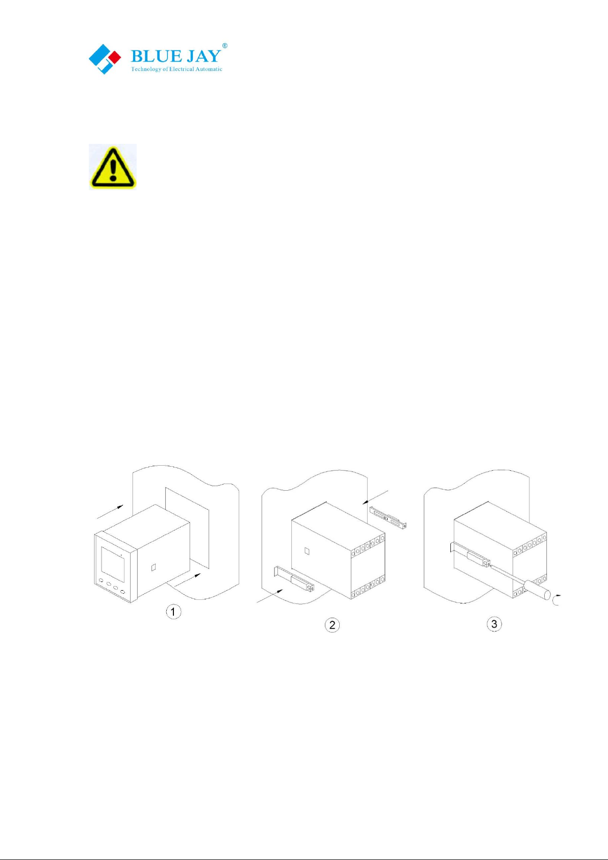
3.1.- Installation
Mounting
Instrument is to be mounted on panel(cut-out 136.5+0.8 x 136.5+0.8 mm). All connections keep
inside the cabinet.
Note:
When the instrument powered on, the terminals could be dangerous to touching and cover
opening actions or elements removal may allow accessing dangerous parts. Therefore, the
instrument must not be used until this is completely installed.

User Manual
Tel: +0086-023-67628702 Email:tech@cqbluejay.com
www.cqbluejay.com
Add: 1802,Building 2,No.88,Jianxin East Road,Chongqing,400020,China - 7 -
Auxiliary power:
BJ-W Series Wireless Temperature Monitor with universal (AC / DC) power input, if not for a
special statement, we provide the 220VAC/DC or 110VAC/DC power interface for standard
products Instruments limit work power supply: AC / DC :80-270V, please ensure that the auxiliary
power can match for BJ-W Series Wireless Temperature Monitor to prevent damage to the
product.
A. Suggest install 1A fuse in the fire line side.
B. For the areas with poor power quality, suggest install lightning surge suppressor and rapid burst
suppressor to prevent lightning strikes
User Manual
Tel: +0086-023-67628702 Email:tech@cqbluejay.com
www.cqbluejay.com
Add: 1802,Building 2,No.88,Jianxin East Road,Chongqing,400020,China - 8 -
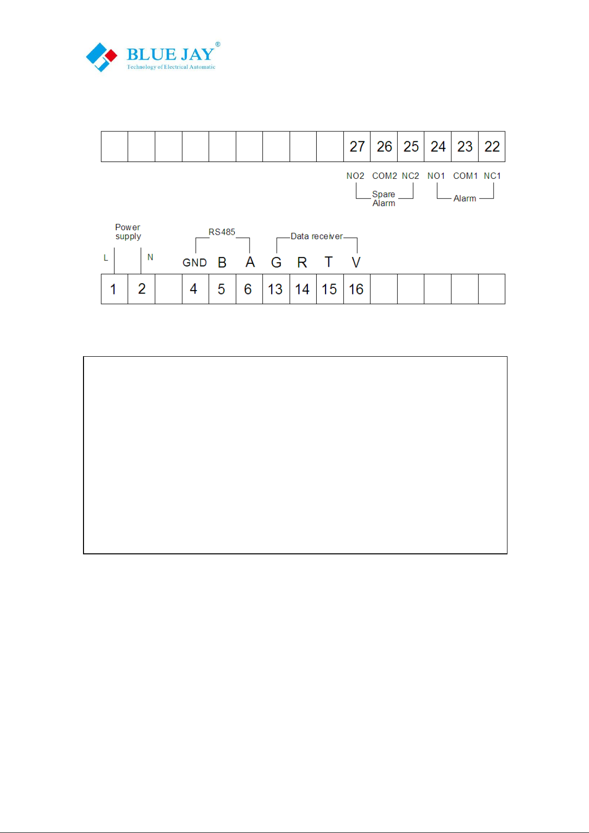
3.2.- Connection terminal (see label on the rear part)
Upper connectionterminal
Lower connection terminal
22 .(NC) Normalclosepin
1. Supplyvoltage input:220 Va.c.
23 .(COM) Ground pin
2. Supplyvoltage input: 0 V
24. (NO) Normal open pin
4. RS-485( GND )
25, 26, 27 for Spare alarm output
5. RS-485( - )
6. RS-485( + )
13(G) 14(R) 15(T) 16(V).connect to data receiver unit
correspondingpin

User Manual
Tel: +0086-023-67628702 Email:tech@cqbluejay.com
www.cqbluejay.com
Add: 1802,Building 2,No.88,Jianxin East Road,Chongqing,400020,China - 9 -
3.3.- Connection drawing for the BJ-W
Warming!!!
If no display on the Base Unit or temperature data is abnormal, please check out following points:
- R485 wiring is correct?
- Sensor is correctlyplaced in the measured surface?
Sensor fixed with close to the
measured surface
For environmental measurement
type, use should set the sensor
case and data sensing unit in a
suitable place
Note: If any special requirement
for the test environment, or
objects, please contact Blue Jay
Technical Support for further
details
User Manual
Tel: +0086-023-67628702 Email:tech@cqbluejay.com
www.cqbluejay.com
Add: 1802,Building 2,No.88,Jianxin East Road,Chongqing,400020,China - 10 -
4. Screen display
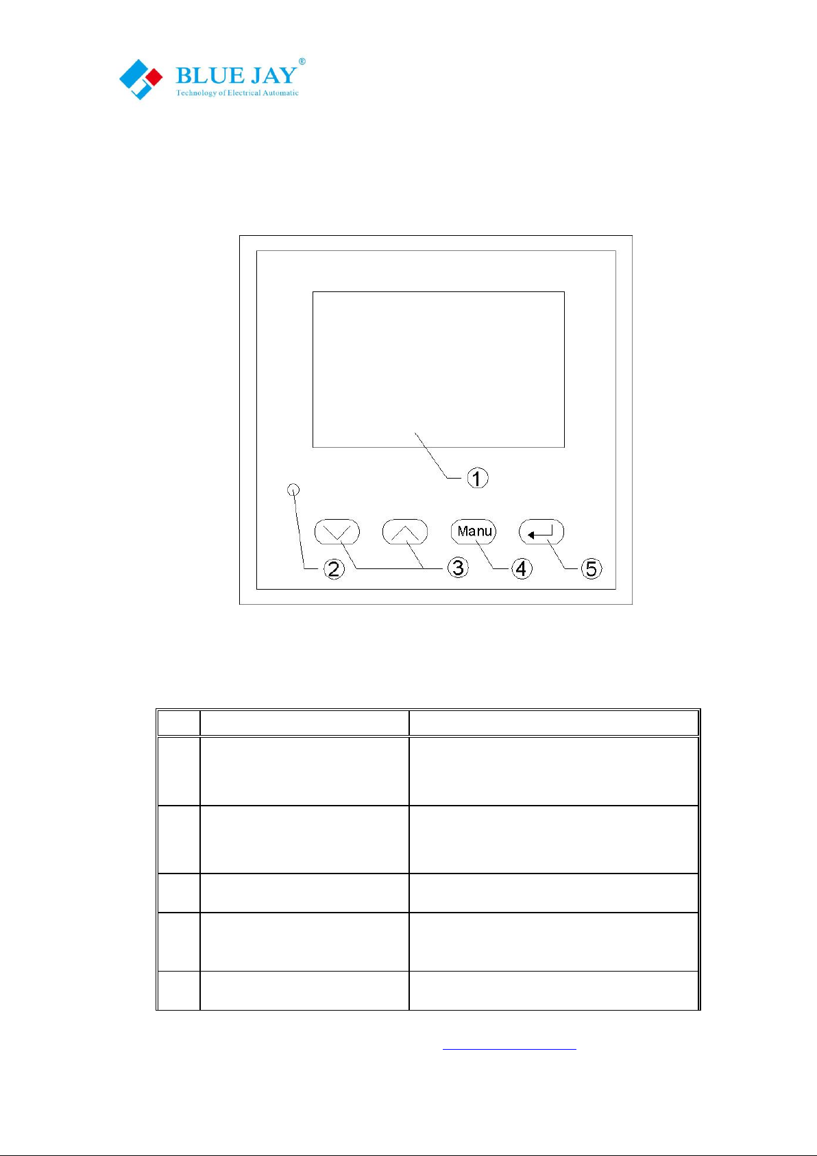
4.1.- Panel diagram
4.2.- Display Summary
No.
Display
Explanation
1
3.3 inch matrix LCD
Show the temperature or humidity data,
Can be customized to different languages
2
Indicator of alarm output
Red LED show the alarm condition, alarm
value can be programmable setting
3*
Up and down key
Set the programming value
4*
Menu key
Used to open the menu and return to
previous menu
5*
Enter key
For menu selection and confirmation
Note:Please see detailinstructions of “*”items at “OPERATION MODE”
User Manual
Tel: +0086-023-67628702 Email:tech@cqbluejay.com
www.cqbluejay.com
Add: 1802,Building 2,No.88,Jianxin East Road,Chongqing,400020,China - 11 -
5.- OPERATION MODE
Notes:
1. If disconnection between the receiver module and the base unit, the display will show
"Broken".
2. If abnormal caused by the temperature transmitter module fault, the display will show
“Error ".
3. If abnormal caused by a broken of thermocouple, the display will show " V broken”
4. If Transmitter battery have low-voltage, the display will show " Under voltage ", in this
case user should replace the batteries immediately
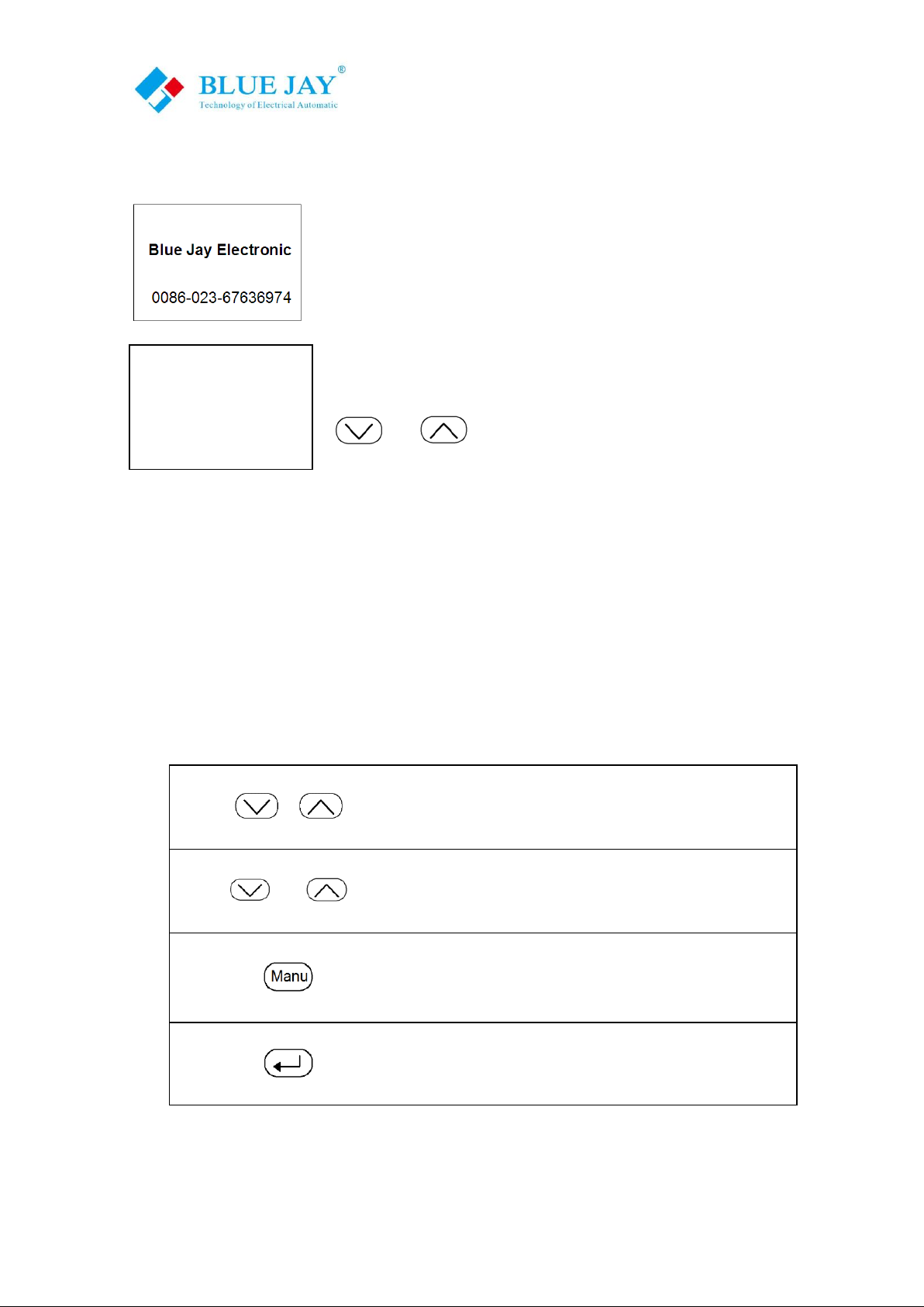
Up or down key to switch the display show
and
At programming display mode,
Toincrease or decrease the value
Open the programming menu
And return to previous menu
Exit it with saving any modification
Or in menu operation to go to the next menu
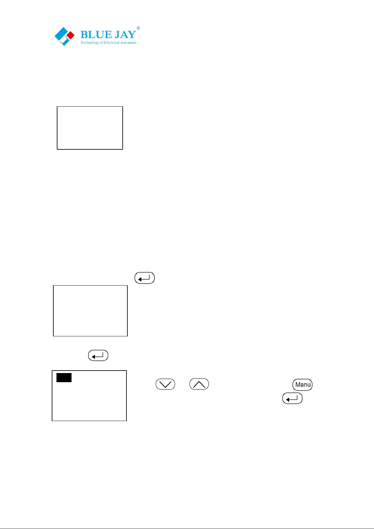
When the power up, the monitor will show the Welcome screen,so
informing about the manufacturer and the Technical servers TEL.
(Accept customized info).
After 2 second, the monitor unit will in to monitor display, show the
page 1 sensor data, current time, month, and year. User can press
and key to switch the data page.
CHANNEL 1=25.3oC
CHANNEL 2=25.8oC
CHANNEL 3=26.1oC
13-06-25 12:22
User Manual
Tel: +0086-023-67628702 Email:tech@cqbluejay.com
www.cqbluejay.com
Add: 1802,Building 2,No.88,Jianxin East Road,Chongqing,400020,China - 12 -
6.- MENU INTRODUCTION
The MENU in BJ-W3000 is performed by several set options.
Once into the MENU, use the keyboard to select different options and enter required variables:
Configuration: free to set systemparameter
SOE: Alarm event, can record last 10 list info
HELP: help info (accept customized info)
6.1.- Setting
In this section, user will set:
1. Time setting
2. Alarm setting
3. COMM setting
4. Note setting
6.1.1.- Set the local time
In setting mode, press key” ”, the monitor will show:
Then press again, the monitor will show:
Use key and to set the value, and press to move
the cursor to set the next parameter, after set, press to save and
escape the local time setting
→Configuration
SOE
HELP
→Time setting
Alarm setting
Comm setting
Note setting
2013—06--23
15:30
[OK]
User Manual
Tel: +0086-023-67628702 Email:tech@cqbluejay.com
www.cqbluejay.com
Add: 1802,Building 2,No.88,Jianxin East Road,Chongqing,400020,China - 13 -
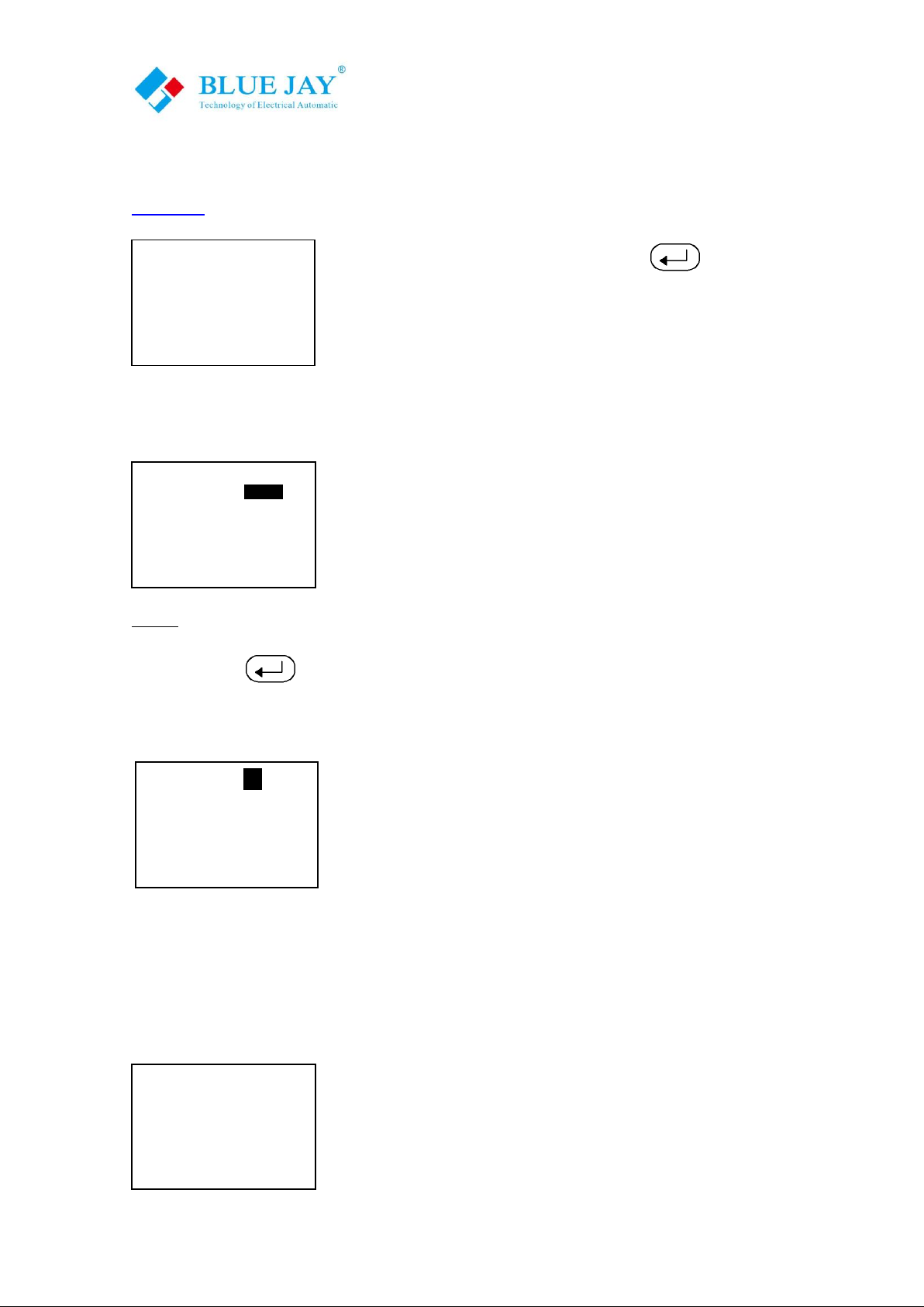
6.1.2.- Set the alarm trig value
The base monitor unit have two relay output for alarm, the connect pin for relay please refer to
chart 3.2.
In setting menu, choose this item, and press to enter the alarm
setting.
The monitor will show:
Monitor can set two alarm output values:
Alarm threshold temperature: for notes onsite person the
temperature change
Trigger threshold temperature: can connect breaker or other
Actuator to forced shutdown circuit, prevent over-temperature damage
Note: Trigger threshold value should be higher than alarm threshold value
After set, press to save and escape the local time setting
6.1.3.- Comm setting
Base monitor unit can be connected to a P.C. With thissystem we
can get all the parameters in one central point of reading. It hasa
serial RS-485 port. If we connect more than one device to the same
communication line (RS-485), we have to assign to each of them a
different code or direction (from 1 to 247), since the P.C. needs the
identification of every measuring point.
Line one means the Communication address, the set value from 1~247
Line two means the “BAUD”, the set value from 4800~38400
6.1.4.- Communication setting
BJ-W Allows customers to define the name of each probe point.
(Default is disabled, accept customized info)
Time setting
→Alarm setting
Comm setting
Note setting
Comm Addr: 05
Baud Ratio: 4800
[OK]
Time setting
Alarm setting
Comm setting
→Note setting
Alarm
Threshold: 50oC
Trigger
Threshold: 60oC
Temperature
HYS : 5oC
[OK]

User Manual
Tel: +0086-023-67628702 Email:tech@cqbluejay.com
www.cqbluejay.com
Add: 1802,Building 2,No.88,Jianxin East Road,Chongqing,400020,China - 14 -
6.2.- Alarm event review
The base monitor unit can record the alarm event, user can easily view the over-temperature
conditions on the unit, without other device
In the setting menu, press and to choose alarm event, the screen will show:
Press the screen show:
If the monitor detects an over-temperature, it will record the alarm type,
data, time, and temperature, the memory standard is 10 items, need
more record capacity, please contact Blue Jay Electronic sales team
Configuration
→SOE
HELP
Event:01 CHANNEL1
Data: 2013-06-25
Time: 14:12
Alarm: T1=27oC

User Manual
Tel: +0086-023-67628702 Email:tech@cqbluejay.com
www.cqbluejay.com
Add: 1802,Building 2,No.88,Jianxin East Road,Chongqing,400020,China - 15 -
7.- COMMUNICATION INTERFACE
7.1.- Connection for the RS485
The composition of the RS-485 cabling must be carried out with a meshed screen cable
(minimum 3 wire), diameter of not less than 0.5mm2, with a maximum distance of 1,200 m
between the BJ… and the master unit. This Bus may connect a maximum of 32 BJ194…
Notes:
1.For communication with the master unit, customers can choose the RS-232 to RS-485 converter
to use
2.Full range of BJ meter RS485 PIN number is 58,59,60
3.Due to product modifications or custom requirements, the interface pin place may be change.
For details, please refer to product label on the rear board

User Manual
Tel: +0086-023-67628702 Email:tech@cqbluejay.com
www.cqbluejay.com
Add: 1802,Building 2,No.88,Jianxin East Road,Chongqing,400020,China - 16 -
7.2.- MODBUS © protocol
Modbus RTU Frame Format:
Address code
1 BYTE
Slave device address 1-247
Function code
1 BYTE
Indicates the function codes like read
coils / inputs
Data code
4 BYTE
Starting address, high byte
Starting address, low byte
Number of registers, high byte
Number of registers, low byte
Error Check code
2 BYTE
Cyclical Redundancy Check ( CRC )
MODBUSFUNCTIONS
Code
Meaning
Description
FUNCTION 03
Reading of n Words
This function permits to read all
the electrical parameters of the
BJ194…series.
FUNCTION 16
Preset Multiple Registers
Write value in to the relevant
register
Note: Blue Jay Default disable the write function, if want change configuration via RS485, please
contact Blue Jay Sales Team before your order.

User Manual
Tel: +0086-023-67628702 Email:tech@cqbluejay.com
www.cqbluejay.com
Add: 1802,Building 2,No.88,Jianxin East Road,Chongqing,400020,China - 17 -
7.3. - Register address table
Host send
Byte
Example
Slave address
Function code
Start register
Data length
CRC code
1
1
2
2
2
01 send to slave "01"
03 read register
00 00 start address 0000
00 04 read 2 register
44 0c CRC code
Slave response
Byte
Example
Slave address
Function code
Data length
register 0
register 1
register 2
register 3
register 4
register 5
register 6
register 7
register 8
register 9
CRC code
1
1
2
2
2
2
2
2
2
2
2
2
2
2
01 data from slave "01"
03 read register
07 7 bytes data followed
00 channel 1 temperature data
00 channel 2 temperature data
00 channel 3 temperature data
00 channel 4 temperature data
00 channel 5 temperature data
00 channel 6 temperature data
00 channel 7 temperature data
00 channel 8 temperature data
00 channel 9 temperature data
00 environment temperature data
00 32 CRC code

User Manual
Tel: +0086-023-67628702 Email:tech@cqbluejay.com
www.cqbluejay.com
Add: 1802,Building 2,No.88,Jianxin East Road,Chongqing,400020,China - 18 -
8.- SAFETY CONSIDERATIONS
All installation specification described at the previous chapters named: INSTALLATION AND
STARTUP, INSTALLATION MODES and PECIFICATIONS.
Note that with the instrument powered on, the terminals could be dangerous to
touching and cover opening actions or elements removal may allow accessing dangerous parts.
This instrument is factory-shipped at proper operation condition.
9.- MAINTENANCE
The product does not require any special maintenance. No adjustment, maintenance or repairing
action should be done when the instrument open and powered on, should those actions are
essential, high-qualified operators must perform them.
Before any adjustment, replacement, maintenance or repairing operation is carried out, the
instrument must be disconnected from any power supply source.
When any protection failure is suspected to exist, the instrument must be immediately put out of
service. The instrument’s design allows a quick replacement in case of any failure.
10.- TECHNICAL SERVICE
For any inquiry about the instrument performance or whether any failure happens, contact to Blue
Jay’s technical service.
Blue Jay - After-sales service
1802,Building 2,No.88,Jianxin East Road,
Chongqing,400020,China
Tel - + 0086 023 67628702
E-mail: tech@cqbluejay.com
Table of contents
Other BLUE JAY Monitor manuals


