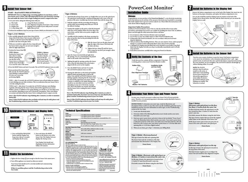
Install Your Sensor Unit
9
START – Read SAFETY PRECAUTIONS first
1. Turn on a high energy-consuming appliance in your house,such as your electric stove or
dryer. This will temporarily increase your electricity consumption and enable the Sensor
Unit to begin reading your meter’s output in less time.
2. Go to your meter, taking the following items with you:
This Guide
1 large Flat Head screwdriver
Sensor Unit
Clear Alignment Template (if you have a Type 4 meter)
Display Unit
Stepping stool or ladder if your utility meter is located
A clean damp cloth higher than eye level
3. Perform the installation steps for your type of meter (which you determined in Step 4).
NOTE: The red STATUS indicator on your Sensor Unit should be lit. If it is flashing
rapidly, press the RESET button.After 10 seconds,it should light up without flashing.
Type 1, 2 & 3 Meters:
1. After carefully wiping the meter dome clean with the
damp cloth, fit the Sensor Unit over your utility meter
as shown, so that the Sensor Head sits as close as
possible to the front of the glass dome.
2. Tighten the hose clamp until the Sensor Unit is snug,
but can move just enough to allow for slight adjustments.
3. Position the Sensor Arm LED:
TYPE 1: The Sensor Arm
must be inline with the
disk (use the line on
the Sensor Arm as a
reference) and the LED
must be centered from
side-to-side.
4.When you have positioned the Sensor head correctly, the red STATUS indicator
starts flashing.
TYPE 1 - The red STATUS indicator starts flashing once per disk revolution.This is
an indication that your Sensor Unit is correctly reading the meter.
TYPES 2 and 3 - The red STATUS indicator starts flashing regularly, indicating that
the Sensor Unit has detected the signal from your meter.Within 1 minute, in addition
to the regular flashing, you should see an extra flash every now and then, depending
on your rate of electricity consumption.These extra flashes are normal, and indicate
that the Sensor Unit is reading the meter’s output correctly.
NOTE: To maximize battery life, the indicator stops flashing after about 2 minutes
in all cases.
Type 4 Meter s:
1. Stand directly in front of your meter, at a height where you can see the optical port.
The optical port itself looks like a small protruding pipe in the center of the top portion
of the meter. Carefully wipe the meter dome clean with the damp cloth.
2. Hold the template with the protruding tab facing you
and the white arrow pointing away from you. Peel off
the adhesive backing.
3. Position the template on the meter so that the horizontal
white line on the template follows the front edge of the
meter dome,and the white arrow points straight to the
optical port.
4. Carefully stick the template to the dome, pressing it in
place on top first, then on the protruding tab down the
front of the dome.
Verify the alignment. If needed, gently remove the template and try again.
5. Slide the Sensor Unit over the glass dome and
align the edges of the Sensor Unit body with the
white side lines.
6. Tighten the hose clamp until the Sensor Unit
is snug, but can move just enough to allow for
adjustments.
7. Open the Sensor Arm latch and sight down the
opening.You see a vertical plastic tab painted white
on the inside of the Sensor body.
8. Sighting through the opening, position the Sensor
Unit so that the white plastic tab on the body is
aligned with the arrow on the template.
9. Keeping the white lines on the body and template
aligned, pull the Sensor Unit towards you gently
and slowly until the red STATUS indicator starts
flashing regularly, indicating that the Sensor Unit
has detected the signal from your meter. Within
1 minute, in addition to the regular flashing, you
should see an extra flash every now and then,
depending on your rate of electricity consump-
tion. These extra flashes are normal, and indicate
that the Sensor Unit is reading the meter’s output
correctly.
If you cannot get the STATUS indicator to react as described within 1 minute, keep
repositioning your Sensor Unit slightly.
NOTE: To maximize battery life, the indicator stops flashing after about 2 minutes.
TYPES 2, 3: The
LED at the end of
the Sensor Arm
must be located
exactly above the
optical port.


