Blue Line Innovations PowerCost Monitor User manual

User Manual
Please read before using this equipment.

1Welcome........................................................................................................................................1
2 Your Powercost Monitor™..........................................................................................................2
2.1 Safety instructions............................................................................................................3
2.2 Care and maintenance......................................................................................................3
3 Determining your utility meter type........................................................................................4
4 Unpacking and verifying basic operation ..............................................................................7
4.1 Powering the display unit ................................................................................................7
4.2 Powering the sensor unit..................................................................................................7
4.3 Verifying the basic operation ..........................................................................................8
5 Sensor unit installation ..............................................................................................................9
5.1 You will need ....................................................................................................................9
5.2 Electromechanical meter................................................................................................10
5.2.1 Preparing your sensor unit..............................................................................10
5.2.2 Installing your sensor unit ..............................................................................10
5.3 Electronic meter (optical port on face)..........................................................................12
5.3.1 Preparing your sensor unit..............................................................................12
5.3.2 Installing your sensor unit ..............................................................................13
5.4 Electronic meter (optical port on face-shims required)................................................14
5.4.1 Preparing your sensor unit..............................................................................14
5.4.2 Installing your sensor unit ..............................................................................15
5.5 Electronic meter (optical port on top) ..........................................................................16
5.5.1 Preparing your sensor unit..............................................................................16
5.5.2 Installing your sensor unit ..............................................................................17
5.6 Re-synchronizing your Display and Sensor Units ........................................................19
6 Setting up your display unit ....................................................................................................20
6.1 Determine your type of billing ......................................................................................20
6.2 Display unit buttons and icons ......................................................................................21
6.3 Setting up for single (flat) rate billing............................................................................24
6.4 Setting up for tiered billing ............................................................................................26
6.5 Setting up for time-of-use billing ..................................................................................29
7 Display unit functions ..............................................................................................................33
7.1 Your display unit ............................................................................................................33
7.1.1 Current Consumption Row..............................................................................33
7.1.2 Total Consumption Row ..................................................................................34
7.1.3 Status Row ......................................................................................................34
7.2 Dollar and cents display mode ......................................................................................35
7.3 Kilowatt and kilowatt-hours mode ................................................................................36
7.4 Temperature display ......................................................................................................37
7.5 Loss of signal display......................................................................................................38
7.6 Resetting the total values................................................................................................39
7.7 Display backlight ............................................................................................................39
8Troubleshooting........................................................................................................................40
Table of Contents

Thank you for purchasing the PowerCost Monitor™ from Blue Line Innovations.
The PowerCost Monitor™ can help you reduce your electricity bill. Our goal is to
empower all households to reduce the amount of electricity they use without having
to dramatically change their lifestyles.At Blueline Innovations Inc., we develop all our
products and services with that goal in mind.
By using this manual and making the PowerCost Monitor™ a regular part of your daily
household management, you can considerably reduce the amount of electricity you
consume without significantly altering the way you live from day to day.
Important: This manual contains important safety and care information, and
provides step-by-step instructions for using this product. Please read this manual
thoroughly, and keep it in a safe place in case you need to refer to it later.
You will find relatively inexpensive and effective tips at www.save-electricity.ca to help
you maximize energy savings.When used in conjunction with the PowerCost Monitor™,
these tips will help you attain your conservation goals.
The PowerCost Monitor™ is straightforward and easy to use. Should you happen to
experience any difficulties with your system, please use the following resources in the
order listed below:
1. The troubleshooting section at the end of this manual.
2. If the problem persists or you have a question that remains unanswered,
additional information is available online at www.bluelineinnovations.com.
3. If none of the above resources contains the solution to your problem, please feel
free to dial our toll free line at 1-866-607-2583. One of our customer support
staff will be happy to assist you. However, we do ask our clients to understand
that this is a last resort to be used only if all else has failed.
1
1
Welcome

2
2
Your PowerCost Monitor™ gives you the advantage of real-time feedback. Tests have
proven that households where real-time feedback is put to good use can reduce their
electricity needs by as much as 5 - 20%.
Real-time feedback means being able to:
• See how much energy your home is using from minute to minute.
• See the effect of turning on or off various electrical devices in your home.
It is important to remember that the PowerCost Monitor™ is just a tool. The amount
of savings is up to you. By striving to keep the values shown on the Display Unit as
low as possible, you will use less electricity - up to 20% less - every month. That will
translate into:
• Real savings on your monthly electricity bill
• Reduced green-house gas emissions
• Reduced demand on the power grid
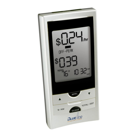
Your PowerCost Monitor™ has an easy to read screen that lights up at the touch
of a button. It can display:
• Your current electricity consumption in dollars and cents per hour
• Your total cost of energy consumed in dollars and cents
• Your current energy consumption in kilowatts
• Your total energy consumed in kilowatt-hours
• The outdoor temperature in Celsius and Fahrenheit
Your PowerCost Monitor™

3
2.1. Safety Instructions
This device does not interfere with your utility meter readings in any way.After the
PowerCost Monitor™ is installed, utility company personnel will still be able to access
your readings normally.
Please read, understand and apply the safety instructions below and read the rest of the User
Manual thoroughly before using this product. These instructions must be followed at all times.
• Do not attempt to repair the PowerCost Monitor™ yourself. If you experience any
difficulties, please refer to the troubleshooting section of this manual or visit
www.bluelineinnovations.com for assistance. If you are still having difficulty please
feel free to call our customer support department toll-free at (866) 607-2583.
• Take precautions when handling batteries. They can cause injuries, burns, and/or
property damage as a result of contact with metal objects, heat, and corrosive materials.
• A damaged LCD display may leak fluids that can be harmful to your health. If any fluid
does leak from the Display Unit after you drop it accidentally, immediately wash it off
with soap and water.
• Do not use this device in aircraft or hospitals. The use of radio frequency devices can
cause malfunctions in the control devices of other sensitive equipment.
2.2. Care and Maintenance
To ensure your PowerCost Monitor™ provides trouble-free service, please read the following
tips and the rest of the User Manual thoroughly before using the system.
• Do not immerse the PowerCost Monitor™ in any liquid.
• Do not use the Display Unit in high moisture areas such as bathrooms.
• Place the Display Unit indoors only. Placing the Display Unit outdoors can result
in damage to the product and will void the warranty.
• Keep this product away from heat sources such as stoves and heaters.
• Do not drop the PowerCost Monitor™ or cause any sudden impact to it.
• If disposing of this product, do so in accordance with your local waste
disposal regulations.

3
4
Your utility meter is most probably located outside your house and it looks like one
of the pictures on the following two pages.
Your PowerCost Monitor™ Sensor Unit has been designed to fit on virtually any
residential meter type, using its built-in clamping strap that goes over the meter dome.
However, the installation procedure varies according to meter types. It is extremely
important that you determine accurately what kind of meter is installed in your home
before proceeding.
Here are a few indications to help you.
There are two families of electrical meters:
• Electromechanical meters (with dials and a spinning disk with a black mark)
• Electronic meters (with a digital readout)
Electronic meters emit an invisible light pulse signal, similar to a remote control
infrared beam, through an optical port. The meter’s optical port can be located:
• On the front of the meter face
• On top of the meter.
The next two pages will help you accurately determine the kind of meter you have
and what it should look like when you complete the installation of your PowerCost
Monitor™ system.
Determining Your Utility Meter Type

5
Electronic Meter
Measure the distance
between the FRONT optical
port and the outer rim of the
dome. It should be NO LESS
THAN 1.5 inches (37 mm).
Use Quick Install Guide
or see section 5.3
>1.5 inches
Optical Port
Find the picture on the left side that looks like your meter. The picture next to it shows how
your sensor should look when properly mounted.
IF YOU DETERMINE THAT YOUR METER IS ONE OF THE TWO FOLLOWING TYPES,YOU CAN FOLLOW
THE PROCEDURES IN THE QUICKSTART GUIDE TO INSTALL YOUR SENSOR UNIT.
Your meter looks like this… … with the Sensor Unit mounted
Electromechanical Meter
Use Quick Install Guide
or see section 5.2

Your meter looks like this… … with the Sensor Unit mounted
6
Electronic Meter
with TOP optical port.
You will need the clear
alignment template.
See section 5.5
Optical Port
Electronic Meter
with FRONT optical port,
LESS THAN 1.5 inches from
outer rim of meter dome.
You will need the rubber
shims. See section 5.4
Electronic Meter
with FRONT optical port,
LESS THAN 1.5 inches from
outer rim of meter dome.
You will need the rubber
shims. See section 5.4
<1.5 inches
Optical Port
<1.5 inches
Optical Port

7
4
Unpacking and Verifying Basic Operation
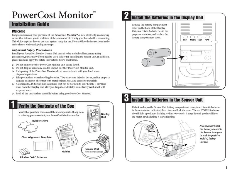
Verify that your box contains all the following components:
• Display Unit
•SensorUnit
• Rubber Shims (2)
• Clear Alignment Template (1)
• Installation Guide, Setup Guide and User Manual
• Alkaline “AA” Batteries (4)
• Installation DVD
After you unpack your PowerCost Monitor™, keep all the packing materials in a safe place.
4.1. Powering the Display Unit
Proceed as follows to power the Display Unit:
1. Remove the Display Unit from the box.
2. Remove the Display Unit battery cover on the back
of the unit, insert two alkaline“AA” batteries in the
orientation indicated and replace the cover.
3. The Display Unit beeps and, after approximately
5 seconds, it displays the start-up screen.
Find an appropriate location for the Display Unit. It must be an indoor location 30 meters
(100 ft.) or less from your home’s utility meter.
Note: To ensure your PowerCost Monitor™ operates at peak performance, you should place
your Display Unit in a room near your utility meter. Ideally, it should be on the same side of
the house where the utility meter is situated. Also, deduct 5 meters for every wall separating
the Sensor Unit from the Display
4.2. Powering the Sensor Unit
1. Open the Sensor Unit battery compartment
by moving the cover latch to the unlocked position.
2. Install two AA alkaline batteries, with the battery
closest to the Sensor Arm going in positive (+) end first.
3. Close the cover and move the cover latch back to the
locked position. The red STATUS indicator lights up.

8
4.3.Verifying the Basic Operation
Your Sensor Unit comes pre-programmed with a unique ID code so it will only work with
your Display Unit. This synchronization step ensures that both the Display Unit and Sensor
Unit operate properly using the same ID code.
1. Press and hold the SYNC button on the front of the Display Unit until you hear a beep
(approx. 3 seconds). The Display Unit displays this screen:
2. Press and release the RESET button on the battery cover of the Sensor Unit.
The display exits ID mode and displays this screen.
If your Display Unit does not react as described above, repeat steps 1 and 2 and,
if you still do not get the expected results, see the Troubleshooting section at the
end of this User Guide.

9
5
5.1.You Will Need…
It is very important to follow the installation instructions for the PowerCost Monitor™
exactly as outlined in this User Guide for the type of meter installed in your home.
Failure to do so will result in incorrect consumption data being displayed and may
void the product warranty.
For best results, install your Sensor Unit on a dry day.Also, to facilitate signal detection,
we recommend you turn on an appliance that uses a lot of energy, like your electric
stove or dryer.
When you are ready, go to your utility meter taking the following items with you:
•ThisUserGuide
• Display Unit
•SensorUnit
• 1 large Flat Head screwdriver
• Stepping stool or ladder if your utility meter is located higher than eye level
•Cleandampcloth
• Supplied Rubber Shims (if needed for your meter type)
• Supplied Clear Alignment Template (if needed for your meter type)
IMPORTANT: Wipe the meter glass dome clean with the damp cloth before proceeding.
WARNING: If your meter is not installed at eye level, please use all the necessary
precautions when on the stepping stool or ladder.
Sensor Unit Installation

10
5.2. Electromechanical Meter
Electromechanical meters have dials on the
face and a spinning disk with a black mark.
The faster the disk spins, the higher your
electricity consumption.
5.2.1. Preparing Your Sensor Unit
Proceed as follows to prepare your Sensor Unit
for mounting on your electromechanical meter.
1. Pull the Sensor Arm latch upward to open it.
2. Extend the Sensor Arm to its full length by
pulling on it. If you accidentally pull it out
completely, push it back into the casing.
3. Close the latch.
5.2.2. Installing Your Sensor Unit
1. Adjust the sensor mounting strap by turning the adjustment screw several turns with
a flat head screwdriver until it is a little wider than the diameter of your meter dome.
2. Fit the Sensor Unit over your utility meter as shown below.
Ensure that the Sensor Arm is as close to the front of the
utility meter glass dome as possible.
3. Tighten the sensor strap adjustment
screw until snug. The Sensor Unit
should still be able to move so
adjustments can be made.
Do not over-tighten!

11
4. Make sure that the Sensor Arm is properly positioned with the disk on the utility meter.
It should be positioned so that the alignment line on the Sensor Arm is inline with the
disk and the sensor head is centered from side-to-side.
NOTE: If the Sensor Arm is not properly positioned, the Sensor Unit may not detect the motion
of the disk and will generate incorrect readings.
5. Press and release the RESET button on the battery cover of the Sensor Unit. The red
indicator on the Sensor Unit lights up and stays on for approximately 45 seconds, until
the Sensor Unit has determined that it is installed on an electromechanical meter. The
red indicator light then turns off and starts flashing every time the black mark on the
disk passes in front of the Sensor Head. The indicator stops flashing after approximately
2 minutes in order to conserve battery power.
6. Tighten the strap adjustment screw until the Sensor Unit cannot be moved easily.
Do not over-tighten!
After a few minutes, if the Sensor Unit indicator does not flash when the black mark
passes, or if it flashes while the black mark is not visible, then the Sensor Arm is not
properly aligned. To re-adjust the Sensor Arm:
1. Open the Sensor Arm latch and gently move the Sensor Arm up or down
a few millimeters to align it with the meter disk.
2. Close the Sensor Arm latch then repeat step 5 above. Continue to do this
until the Sensor Unit consistently and only flashes when the black mark
passes in front of the Sensor Head.
7. Now read section 5.6 to re-synchronise your Display and Sensor Units.

12
5.3. Electronic Meter (Optical Port on Face)
Electronic meters have digital readouts, as well as an optical port which emits light pulses similar
to the infrared light produced by a television remote control.
This section deals with meters where the optical port is located on the face, more specifically,
where the distance between the port and the outer rim of the meter dome is AT LEAST 1½
inches (37 mm). If in doubt, physically measure the distance between your port and the outer
rim of the dome. If it is less than 1½ inches (37 mm), you must follow the instructions in section
5.4 to install your Sensor Unit.
5.3.1. Preparing Your Sensor Unit
Your Sensor Unit is ready to be installed from the box.
However, it is recommended that you do the following:
1. Pull the Sensor Arm latch upward to open it.
2. Ensure that the Sensor Arm is completely pushed
in as far as it will go.
3. Close the latch.
>1.5 inches
Optical Port

13
5.3.2. Installing Your Sensor Unit
1. Adjust the sensor mounting strap by turning the adjustment screw several turns with
a flat head screwdriver until it is a little wider than the diameter of your meter dome.
2. Fit the Sensor Unit over your utility meter by sliding
the clamp around the meter dome. Ensure that the
Sensor Arm is as close to the front of the utility meter
glass dome as possible.
3. Tighten the sensor-strap adjustment screw until
snug.The Sensor Unit should still be able to move
so adjustments can be made. Do not over-tighten!
4. Make sure that the Sensor Arm is properly positioned
on the utility meter. It should be positioned so that the
Sensor Head is located exactly above the optical port.
5. Press and release the RESET button on the
battery cover of the Sensor Unit. The red
indicator on the Sensor Unit lights up and
stays on until the Sensor Unit has determined
that it is installed on an electronic meter. The
red indicator light then begins to flash irregularly.
The indicator stops flashing after approximately
2 minutes in order to conserve battery power.
6. Tighten the strap adjustment screw until
the Sensor Unit cannot be moved easily. Do not over-tighten!
If the Sensor Unit indicator does not begin to flash irregularly after about
5 minutes, the Sensor Arm is not properly positioned over the optical port
or the glass dome is dirty. Clean the dome and repeat step 5 above.
7. Now read section 5.6 to re-synchronise your Display and Sensor Units.

14
5.4. Electronic Meter (Optical Port on Face – Shims Required)
Electronic meters have digital readouts, as well as an optical port which emits light pulses similar
to the infrared light produced by a television remote control.
This section deals with electronic meters that have their optical port on the face, at a distance
LESS THAN 1.5 inches (37 mm) from the outer rim of the meter dome. If in doubt, physically
measure the distance between your port and the outer rim of the dome. If it is equal to or more
than 1.5 inches (37 mm), follow the instructions in section 5.3 to install your Sensor Unit.
Here are two examples of such meters.Although the meter in the photo on the right hand side
appears to have two optical ports, it has only one, and it is the opening located closest to the
meter’s center.
5.4.1. Preparing Your Sensor Unit
Proceed as follows:
1. Pull the Sensor Arm latch upward to open it.
2. Ensure that the Sensor Arm is completely pushed
in as far as it will go.
3. Close the latch.
In these electronic meters, the optical port is too close to the dome’s outer rim for it to be
possible to position the Sensor Head over the port, because the Sensor Arm is too long,
even when fully pushed in.
Optical Port
Optical Port

15
The supplied rubber shims are required to achieve proper installation.
4. Loosen the hose clamp and determine by eye if one or two shims will be required.
5. Remove the adhesive backing from one of the shims and press the shim in place onto
the underside of the Sensor body.
IMPORTANT: DO NOT stick the shim to the glass dome.
6. If required, remove the adhesive backing from the second shim and press the second
shim onto the first.
5.4.2. Installing Your Sensor Unit
7. Fit the Sensor Unit, with the shims installed, over your utility meter by sliding the
assembly around the meter dome. Ensure that the Sensor Arm is as close to the front
of the utility meter glass dome as possible.
8. Tighten the sensor-strap adjustment screw until snug. The Sensor Unit should still be
able to move so adjustments can be made. Do not over-tighten!
9. Make sure that the Sensor Arm is properly positioned
on the utility meter. It should be positioned so that the
Sensor Head is located exactly above the optical port.
10. Press and release the RESET button on the battery
cover of the Sensor Unit. The red indicator on the
Sensor Unit lights up and stays on until the Sensor
Unit has determined that it is installed on an
electronic meter. The red indicator light then begins
to flash irregularly. The indicator stops flashing after
2 minutes in order to conserve battery power.
11. Tighten the strap adjustment screw until the Sensor Unit cannot be moved easily.
Do not over-tighten!
If the Sensor Unit indicator does not begin to flash irregularly after about 5 minutes,
the Sensor Arm is not properly positioned over the optical port or the glass dome
is dirty. Repeat steps 10 and 11 above.
12. Now read section 5.6 to re-synchronise your Display and Sensor Units.

5.5. Electronic Meter (Optical Port on Top)
Electronic meters have digital readouts, as well as an optical port which emits light pulses similar
to the infrared light produced by a television remote control. This section deals with electronic
meters that have their optical port on the top.
These meters require that you reconfigure the Arm in the Sensor Unit.
5.5.1. Preparing Your Sensor Unit
1. Pull the Sensor Arm latch upward to open it.
2. Gently pull the Sensor Arm completely out
of the Sensor Body.
3. Turn the Sensor Arm over.
16
Optical Port

4. Push the smaller end of the Sensor Arm
upwards through the latch opening.
5. Push the Sensor Head behind the strap,
and as far down as it will go into the bottom
cavity of the body.
6. Tuck the wire neatly into the side cavity.
7. Close the latch.
5.5.2. Installing Your Sensor Unit
To help with the positioning of the Sensor Head exactly over the optical port, Blueline
Innovations has supplied you with a clear plastic template that goes on top of the meter dome.
8. Stand directly in front of your meter, at a height where you can see the optical port.
The optical port itself looks like a mall pipe in the center of the top portion of the meter.
9. Hold the template with the protruding tab facing towards you and the white arrow
pointing away from you. Peel off the adhesive backing.
10. Position the template on the meter so that the
horizontal white line on the template follows
the front edge of the meter dome, and the white
arrow points straight to the optical port.
11. Carefully stick the template to the dome. Press on
the template on top of the dome, and then press
on the protruding tab down the front of the dome.
Verify the alignment. If needed, gently remove the
template and try again.
17
Optical Port

12. Slide the Sensor Unit over the glass dome
and align the edges of the Sensor Unit body
with the white sidelines on the template.
13. Tighten the hose clamp so that the Sensor Unit is snug but can still move easily.
14. Push the Sensor Unit back on the glass dome as far as it will go.
15. Open the Sensor Arm latch and sight down the
opening.You see a vertical plastic tab painted
white on the inside of the Sensor body.
16. Align the white plastic tab with the white line on the template.
17. Press and release the RESET Button. The red STATUS indicator lights up.
18. Keeping the white lines on the body and template
aligned, pull the Sensor Unit towards you gently
and slowly until the red STATUS indicator starts
flashing, regularly at first, then irregularly.
19. When the STATUS indicator is flashing irregularly,
your Sensor Unit is properly aligned and is sending
signals to your Display Unit. Tighten the clamp to
secure the Sensor Unit to the meter dome.
20. Now read section 5.6 to re-synchronise your Display and Sensor Units.
18
Other manuals for PowerCost Monitor
2
Table of contents
Other Blue Line Innovations Measuring Instrument manuals
