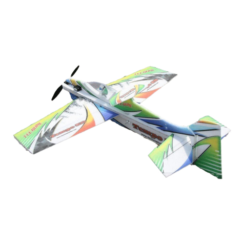
Blue Max Global Arf Operator's manual

1
Instructions for Final Assembly
Version V1.0 4-99 Kit # 232500 All Contents © Copyright 1999
Commemorate the Aviation's beginnings with the new Global Blue Max ARF.
A time when the nose skid was as important as the tail skid to safety minded
pilots landing on unprepared airfields, planes of this style used cutting edge
technology for their day. The Blue Max remembers those years long past. It's
open cockpit, wire spoke wheels and open framework capture a more experi-
mental time in aviation. The high lift wing and generous wing area mean
super slow stall speed and very forgiving flight characteristics. Don't be sur-
prised if you see beginners with this plane. Our test pilots say this plane is
easier to fly than most .40 size trainer planes. And unlike the grossly under-
powered airplanes of yesteryear, the Blue Max is favorably powered using a
.40 size two stroke or a .52 size four stroke. So put on your scarf and your
goggles and get ready to go back into time. Oh, and don't forget to load that
cannon!
40 - 46 Size Almost Ready to Fly

2
TABLE OF CONTENTS
To make your modeling experience totally enjoyable, we recommend that you get experienced, knowledgable help
with assembly and during your first flights. Your local hobby shop has information about flying clubs in your area
whose membership includes qualified instructors. You can also contact the AMA at the address below.
Academy of Model Aeronautics
5151EastMemorialDrive
Muncie,IN. 47302-9252
(800)435-9262
www.modelaircraft.org
Global guarantees this kit to be free from defects in both material and workmanship, at the date of purchase. This does
not cover any components parts damaged by use, misuse or modification. Inno caseshall Global'sliability exceedthe
originalcostof thepurchasedkit.
In that Global has no control over the final assembly or material used for final assembly, no liability shall be assumed for
any damage resulting from the use by the user of the final user-assembled product. By the act of using the final user-
assembled product, the user accepts all resulting liability.
Kit Contents...................................................3
Additional Items Required................................3
Tools and Supplies Needed..............................3
Field Support Equipment Needed......................3
Metric Conversion Chart.................................3
Wing Assembly...............................................4
Install the Dihedral Braces.........................4
Joining the Wing Halves.............................5
Wing Mounting................................................5
Install the Wing Hold Down Dowels...........5
Aligning the Wing to the Fuselage...............6
Install the Wing Struts................................6
Horizontal Stabilizer Mounting..........................6
Align the Horizontal Stabilizer.....................6
Mounting the Horizontal Stabilizer...............7
Vertical Stabilizer Mounting..............................8
Align the Vertical Stabilizer........................8
Mounting the Vertical Stabilizer..................8
Control Surface Installation..............................8
Hinge the Ailerons....................................8
Hinge the Elevator....................................9
Install the Tail Wheel Wire.........................9
Hinge the Rudder......................................9
Mounting the Tail Wheel Bracket.............10
Installing the Tail Wheel...........................10
Main Landing Gear........................................10
Aligning the Main Gear Assembly............10
Installing the Main Gear Assembly...........10
Installing the Main Gear Wheels...............11
Engine Mounting............................................11
Mounting Engine to Motor Mount.............11
Aligning the Motor Mount........................11
Mounting the Engine to Firewall...............12
Nose Skid.....................................................12
Align the Nose Skid.................................12
Installing the Nose Skid............................12
Fuel Tank......................................................13
Fuel Tank Assembly................................13
Fuel Tank Installation...............................13
Throttle Linkage............................................14
Installing the Throttle Linkage..................14
Servo Installation...........................................14
Installing the Fuselage Servo Tray............14
Installing the Aileron Servo Tray...............14
Installing the Aileron Servo......................15
Installing the Fuselage Servos..................15
Throttle Connector........................................15
Installing the Throttle Connector...............15
Rudder Pushrod............................................16
Installing the Rudder Control Horn...........16
Installing the Rudder Pushrod..................16
Elevator Pushrod..........................................17
Installing the Elevator Control Horn..........17
Installing the Elevator Pushrod.................17
Aileron Linkage............................................18
Installing the Aileron Linkage...................18
Pilot and Cannon...........................................19
Barrel Seat Assembly..............................19
Pilot and Cannon Assembly......................19
Barrel Seat Installation.............................20
Pilot Installation.......................................20
Cannon Installation..................................20
Final Assembly..............................................21
Installing the Receiver and Battery...........21
Installing the Switch................................21
Installing the Fuel Lines...........................21
Installing the Propeller.............................21
Balance........................................................21
Lateral Balance......................................22
Control Throws.............................................22
Flight Preparation..........................................22
Preflight Check.......................................23
Basics of Flight.............................................23
Product Evaluation........................................26

3
KIT CONTENTS
Thisinstruction manualis designedto helpyou builda straight,great flyingairplane. Please readthis
manual thoroughly before beginning assembly of your new Blue Max. Use the parts listing below to
identifyand separate all partsbeforebeginningassembly.
**KITCONTENTS**Wehaveorganizedthepartsastheycomeoutoftheboxforbetteridentification
duringassembly. Werecommendyouregroupthepartsinthesamemanner. Thiswillensureyouhaveall
ofthepartsrequiredbeforeyoubeginassemblyandwillalsohelpyoufamiliarizeyourselfwitheachpart.
o{2} NylonClevises w/2mm I.D. Hole
o{2} 2mmx150mm ThreadedRod
o{2} Nylon Snap Keepers
o{2} Nylon Adjustable Control Horns
o{1} 2mmx300mmPushrodWire
o{1} Adjustable Servo Connector Assembly
o{2} Nylon Motor Mount Beams
o{4} 3mmx25mm MachineScrews
o{4} 3mmx20mm MachineScrews
o{4} 3mm Nylon Insert Nuts
o{4} 3mm Blind Nuts
o{12}3mm Flat Washers
o{1} AileronServo Tray (W-39)
o{1} ForwardDihedral Brace (W-40)
o{1} Rear Dihedral Brace (W-41)
o{2} WingHold Down Dowels (W-43)
o{1} Fuselage Servo Tray (D-47)
o{6} 3mmx10mm MachineScrews
o{6} 3mm Flat Washers
o{4} 3mmx12mm WoodScrews
o{2} Wing Halves w/Ailerons and Hinges
o{1} Fuselage
o{1} HorizontalStabilizer w/Elevator and Hinges
o{1} VerticalStabilizer w/Rudder and Hinges
o{2} Wing Struts
o{1} Wire Main Gear Assembly
o{1} Wire Nose Skid
o{2} Nylon Mounting Straps w/4mm Slot
o{5} Nylon Mounting Straps w/3mm Slot
o{2} 127mm Diameter Wire Spoke Wheels
o{2} Nylon Axle Spacers
o{2} Wheel Collars w/3mm x 6mm Machine Screws
o{14}3mm x 12mmWoodScrews
o{1} Tail Wheel Wire w/ Mounting Bracket
o{1} 25mm Diameter Tail Wheel
o{2} Wheel Collars w/3mm x 6mm Machine Screws
o{3} 3mmx12mm WoodScrews
o{1} 990mmNylon Pushrod
o{1} 1.5mm x 50mmThreadedWirew/Z-Bend
o{1} 1.5mm x 45mmWire ThreadedEachEnd
o{1} Nylon Clevis w/1.5mm I.D.Hole
o{1} Nylon Control Horn
o{1} Nylon Control Horn Backplate
o{2} 2mmx15mm MachineScrews
o{1} Molded Fuel Tank
o{1} 20mmFront Squash Plate
o{1} 18mmRear Squash Plate
o{1} Rubber Stopper
o{1} 70mmLength of Fuel Tubing
o{1} Metal Weighted Pick-Up
o{3) Aluminum Tubes
o{1} 3mmx20mm MachineScrew
o{1} 990mmNylon Pushrod
o{1} 1.5mm x 50mmThreadedWirew/Z-Bend
o{1} 1.5mm x 45mm Wire Threaded Both Ends
o{1} Nylon Clevise w/1.5mm I.D. Hole
o{1} Nylon Control Horn
o{1} Nylon Control Horn Backplate
o{2} 2mmx15mm MachineScrews
RUDDERCONTROL SYSTEM
ELEVATORCONTROLSYSTEM
TAILWHEELASSEMBLY
MAINGEARASSEMBLY
AIRFRAMEASSEMBLIES AILERON CONTROLSYSTEM
MOTOR MOUNT ASSEMBLY
MISCELLANEOUSITEMS
FUELTANK
THROTTLECONTROLSYSTEM
PILOTAND CANNON ASSEMBLY
o{1} Prepainted Balsa Cannon Mount
o{2} Plastic Body Halves
o{2} Plastic Cannon Halves
o{2} Plastic Head Halves
o{1} BalsaBarrel Seat Platform
o{1} PlasticBarrel Seat
o{1} PlasticBarrel Seat Back

4
ADDITIONAL ITEMS REQUIRED
o{1}Hitec4 orMore ChannelRadio w/4 Servos
o{1}Dubro Foam Rubber # 513
o{1}GlobalFuel Line# 115923
o{1}Arco # 64 Rubber Bands # 24649
FOR2-STROKE ENGINE
o{1}MagnumXL .40-.46Two Stroke
o{1}Magnum1/4” SpinnerNut# 237310
o{1}PropellerToSuitEngine
o{1}ThunderboltGlowPlug# 115493
FOR4-STROKE ENGINE
o{1}MagnumXL .52RFSFour Stroke
o{1}Magnum1/4” SpinnerNut# 237310
o{1}PropellerToSuitEngine
o{1}ThunderboltGlowPlug# 115490
TOOLS AND SUPPLIES NEEDED
oKwikBond ThinC/A #887500
oKwikBond Thick C/A# 887510
oKwikBond 5Minute Epoxy# 887560
oKwikBond 30Minute Epoxy# 887565
oWilholdSilicon Sealer# 00684
oElectricDrill
oAssortedDrillBits
oModelingKnife
oWireCutters
oMachineOilorVaseline
oStraightEdgeRuler
oDremelToolw/AssortedBits
oPhillipsScrewdriver
oZ-BendPliers
o3mmHexWrench
oBuildersTriangle
o220Grit Sandpaper
oMaskingTape
oPaperTowels
oRubbingAlcohol
FIELD SUPPORT EQUIPMENT NEEDED
oMagnum12VElectricStarter(#361006)
oMagnum12V FuelPump(# 237377)
oMagnumLockingGlowClip (# 237440)
oGlobal12V Battery (# 110171 )
oGlobal 12V Charger (# 110270 )
oMagnumPower Panel(# 237390)
oGlobalFieldBuddyFlightBox(#233072)
oMagnum4-WayWrench(#237420)
TOFINISHPILOT ANDCANNON
oTestors ContourPutty #3511X
o320Grit Sandpaper
oFind&MediumPaintBrushes
o3MFine Line Masking Tape# 218-06300
oCoveriteFlat ClearPaint #COVR1280
oPaintThinner
oTan, White,Brown andOrange -Mix to
makeskincolor andlip color
oFlatBlack - Eyebrows,Mustache, Hair
andCannon
oWhiteandBlue -Eyes
oLightBlue-Body
oGold- SimulateButtonsandStrapsofJacket
oBrass-CannonTrim
oBrown- CannonBarrel Seat
METRIC CONVERSION CHART
Toconvert inches intomillimeters: Inchesx25.4= MM
1/64” = .4mm
1/32” = .8mm
1/16” = 1.6mm
3/32” = 2.4mm
1/8” = 3.2mm
5/32” = 4.0mm
3/16” = 4.8mm
1/4” = 6.4mm
3/8” = 9.5mm
1/2” = 12.7mm
5/8” = 15.9mm
3/4” = 19.0mm
1” = 25.4mm
2” = 50.8mm
3” = 76.2mm
6” = 152.4mm
12” = 304.8mm
18” = 457.2mm
21” = 533.4mm
24” = 609.6mm
30” = 762.0mm
36” = 914.4mm

5
**SUGGESTION** To avoid scratching your new airplane, do not unwrap the pieces until they are
needed for assembly. Cover your workbench with an old towel or brown paper, both to protect the aircraft
and to protect the table. Keep a couple of jars or bowls handy to hold the small parts after you open the
bags.
**NOTE** Please trial fit all the parts. Make sure you have the correct parts and that they fit and are
aligned properly before gluing! This will assure proper assembly. Since the Blue Max is hand made from
natural materials, every plane is unique and minor adjustments may have to be made. However, you
should find the fit superior and assembly simple.
If you should find a part missing or have questions about assembly, please call or write to the address below:
CustomerService Center
18480Bandilier Circle
FountainValley, CA. 92728
Phone:(714) 963-0329
Fax:(714)964-6236
E-Mail:[email protected]
o3) Test fit thedihedral bracesinto their re-
spectiveboxesineach wing half. W-40fitsinto
theforwardbox andW-41fits into therearbox.
Thebracesshouldslideintoeachwinghalfupto
thecenterlines. Iftheydonot, remove themand
lightlysandtheedgesandtipofeachoneuntilthe
proper fit is obtained. Seephoto# 2below.
PARTSREQUIRED
WING ASSEMBLY
INSTALLTHEDIHEDRALBRACES
o{2} Wing Halves w/Ailerons and Hinges
o{1} Forward Dihedral Brace (W-40)
o{1} Rear Dihedral Brace (W-41)
o1) Lookat thefaceof eachrootribon both
winghalves. Noticehowtheexcesscoveringma-
terialoverlapsontothem. Usingamodelingknife,
carefullycutawaythecoveringfrom both ofthe
root ribs. Leave about 1/16” of covering over-
lappingsoitdoes not pullaway.
Itisimportantthatthecoveringberemoved
fromthe rootribs. This willensure an ad-
equate wood-to-wood glue joint and prevent
wingfailureduringflight.
o2) Usinga ruler and a pen, locateandmark
the center section of the forward and reardihe-
dral braces(W-40 and W-41). Draw a vertical
line at this location on both braces. Seephoto
# 1below.
Thedihedral bracesare cut inthe shapeof
a"V". Theyshouldbeinstalledwiththe"V"
shapefacingupright to formtheproperdihedral
anglewhenthewingsarejoined.
o4) Test fitbothof thewinghalves together
withthedihedralbracestemporarilyinstalled. Do
notgluetheminatthistime! Thewing halves
shouldfittogethertightlywithlittleornogapsinthe
centersection joint. If thecentersection jointis
nottight,removethewinghalvesandlightlysand
the edges and tips of each brace. Reinstall the
winghalvesandbracesandtestthefituntilyouare
satisfied thatthecentersectionjointistight.
o5) When satisfied with the fit of the wing
halves,removethe dihedral braces.
Photo # 1
Photo # 2
FORWARD
DIHEDRAL
BRACE
REAR
DIHEDRAL
BRACE
DRAW CENTERLINE
DRAW CENTERLINE
SLIDE IN UP
TOCENTERLINE
SLIDE IN UP
TOCENTERLINE

6
o8) Once the epoxy has cured, trial fit both
winghalvestogethertodoublecheckthatthewing
halvesstillfitcorrectly.
o9) MixagenerousamountofKwikBond30
MinuteEpoxy. Applyathinlayerofepoxytothe
exposedhalvesofbothdihedralbraces,theinside
ofbothdihedral braceboxesinthesecondwing
halfandtheentiresurfaceofbothrootribs. Make
suretouse enough epoxytofillany gaps.
o10) Slidethetwo winghalvestogether and
carefullyalignthemattheleadingandtrailingedges.
Wipeawayanyexcessepoxyusingapapertowel
andrubbingalcohol. Usemaskingtapetoholdthe
winghalves inplace untilthe epoxy cures. See
photo#4 below.
JOININGTHEWINGHALVES
o6) Mix a generous amount of Kwik Bond
30MinuteEpoxy. Working withonlyonewing
half for now, apply a thin layer of epoxy inside
both dihedral brace boxes and on only half of
eachdihedral brace. Make suretocover thetop
andbottom as well as the sides anduse enough
epoxytofillanygaps.
o7) Slidethedihedral bracesinto theboxes
uptothecenterlines. Removeanyexcess epoxy
before it dries using a paper towel and rubbing
alcohol. Allow the epoxy to cure before pro-
ceeding. Seephoto# 3below.
Photo # 4
Photo # 3
PARTSREQUIRED
WING MOUNTING
INSTALLTHEWINGHOLDDOWNDOWELS
o{1} Fuselage
o{2} WingHold Down Dowels (W-43)
o{2} Wing Struts
o{6} 3mmx10mm MachineScrews
o{6} 3mm Flat Washers
o1) Usingamodelingknife,carefullyremove
thecoveringfromoverthefourpredrilledholesin
thefuselagesides. Twoholesarelocatedoneach
side of the fuselage. Seephoto#5below.
Photo # 5
o2) Slideonewingholddowndowelthrough
thetwo forward holesin thefuselage sidesand
thesecond dowel throughthe tworear holesin
the fuselage sides. Adjust the dowels so both
ends of each dowel protrude from the fuselage
sides an equal amount. See photo#6below.
Photo # 6
o3) Whensatisfiedwiththefit,useapenand
place a mark on each dowel at the point where
theyexit the fuselage sides.
o4) Remove the dowels and mix a small
amountofKwikBond30MinuteEpoxy. Apply
athinlayerofepoxytotheinsideedgesofallfour
holesinthefuselage. Carefullyslide the dowels
intoplace upto the marksmade. Double check
thatthey arecentered anduse papertowels and
rubbingalcoholtoremoveanyexcess epoxy be-
foreitcures.
MASKING
TAPE
MASKING
TAPE
REMOVE COVERING
(both sides)
REMOVE COVERING
(both sides)
WINGHOLD
DOWNDOWEL

7
o5) Usingarulerand a pen,locateandmark
thecenterlineofthefuselageatboththefrontand
rear of the wing saddle. Place a mark at both
locations. Seephoto # 7below.
Thesetwomarkswillhelpyoualignthewing
whenyouinstallitonthefuselage. Youmay
wish to make these marks in permanent ink so
youcan align the wing correctly each timeyou
installthewing. Thiswillensurethewingisaligned
properlyeachtimeyouflytheairplane.
o6) Therearetwopreinstalledblindnutsthat
areused to mountthe wing struts to the bottom
of the fuselage. Using a modeling knife, care-
fullyremovethecoveringfromoverthetwoblind
nut holes on the bottom of the fuselage. The
holesarelocated 1/2”infrom the fuselagesides
and 8-1/4” back from the front of the firewall.
See photo # 8 below.
o8) Placethewingintothewingsaddle. Align
thecenterlineofthewingatboththeleading and
trailingedges with thetwo marksyou madeon
thefuselage.
o9) Using a couple of # 64 rubber bands,
temporarilysecurethewinginplacemakingsure
itisaligned. Tocorrectlyinstalltherubberbands,
hookone overone ofthe frontwing holddown
dowels,carefully pull itback over thetop of the
wingandhook itoverthe rear holddowndowel
on the same side. Install two rubber bands on
eachside for now.
o10) Bolt the wing struts to the wing and to
thefuselageusing thesix3mm x 6mmmachine
screws and six 3mm flat washers. It may be
necessaryto move thewing slightly toproperly
align the holes in the struts with the blind nuts.
See photo # 10 below.
ALIGNINGTHEWINGTOTHEFUSELAGE
Photo # 7
INSTALLTHEWINGSTRUTS
Photo # 8
o7) Therearealsotwoblindnutspreinstalledin
eachwinghalf. Theyarelocatedinplywoodgus-
sets,20”outfromthecenterlineofthewing. The
rearblindnutis2-3/4”forwardofthetrailingedge
andthefrontblindnutis3”backfromtheleading
edge. Usingamodelingknife,carefullyremovethe
coveringfromoverthetwoblindnutholesineach
winghalf. Seephoto#9attopright.
Photo # 9
Photo # 10
PARTSREQUIRED
HORIZONTAL STABILIZER
MOUNTING
ALIGNTHEHORIZONTALSTABILIZER
o{1} HorizontalStabilizer w/Elevator and Hinges
o1) Removetheelevatorfromthehorizontal
stabilizerand set it asidefornow. Turnthestabi-
lizerupsidedownonyourworksurface. Thebot-
tomsideistheflatsideandshouldbefacingup.
MARK
CENTERLINE MARK
CENTERLINE
REMOVE
COVERING 8-1/4”
WINGTIP
REMOVE COVERING AILERON
3mm FLAT
WASHER
3mm x
6mm
SCREW
3mm x 6mm
SCREW
3mm FLATWASHER

8
o3) Usingaruleranda pen, locateand place
amarkatthecenterlineofthefuselageatthefront
andrearofthestabilizermountingplatform. These
markswill beused toline upthe stabilizerwith
the fuselage. See photo#12 below.
o2) Usingarulerandapen, locate andmark
the centerline of the horizontal stabilizer at the
trailing edge and place a mark. Use a triangle
andextend this mark,fromback tofront,across
the bottom of the stabilizer. Alsoplace center-
linemarksonthetopofthestabilizerattheleading
andtrailingedges only. Seephoto #11below.
Photo # 11
Photo # 12
o4) Attach the wing to the fuselage and re-
movebothailerons. Setthehorizontalstabilizer
ontothestabilizermountingplatformonthefuse-
lage. Align the centerline marks on top of the
stabilizerwith the centerline marks at the front
andrearofthestabilizermountingplatform. When
themarksarealigned hold thestabilizerinposi-
tionusingacoupleofT-pins.Alignthehorizontal
stabilizerwiththewing. Whenviewedfromthe
rear,thehorizontalstabilizershouldbelevelwith
the wing. If it is not level, use sandpaper and
sanddownthehigh side ofthestabilizermount-
ingplatformuntiltheproperalignmentisachieved.
Thetipsofthestabilizershouldalsobeequaldis-
tancefrom thetips of thewing. Seefigures#1
and# 2 attop right.
Figure# 1
Figure# 2
o5) Whenyouaresatisfiedwiththealignment,
holdthestabilizerinplacewith T- pinsor mask-
ingtape, but donotglue atthistime.
o6) Withthestabilizerheldfirmlyinplace,use
a pen and draw aline on the stabilizerwhere it
and thefuselage sides meet. Do thison both the
rightandleftsidesonthebottomofthestabilizer.
o7)Removethestabilizer. Usingthelinesyou
justdrewasaguide,carefullyremovethecovering
frombetweenthem,usingamodelingknife. See
photo# 13below.
MOUNTINGTHEHORIZONTALSTABILIZER
Photo # 13
When cutting through the covering to re-
moveit, cut withonly enoughpressure to
onlycutthroughthecoveringitself. Cuttinginto
thebalsastructuremayweakenitandcausepos-
siblefailureinflight.
DRAW
CENTERLINE
DRAW
CENTERLINE
DRAW
CENTERLINE
A
BA1 B1
CC1
REMOVE
COVERING

9
Figure# 3
o8) Whenyou are satisfied thateverythingis
alignedcorrectly, mix up agenerous amountof
KwikBond30MinuteEpoxy. Applyathinlayer
tothebottomofthestabilizer mounting areaand
tothetop ofthestabilizer mounting platformon
the fuselage. Set the stabilizer in place and re-
align. Double check all of your measurements
oncemore before theepoxycures. Holdthesta-
bilizerin place withT-pins or maskingtape and
removeanyexcessepoxyusingpapertowelsand
rubbingalcohol.
PARTSREQUIRED
VERTICAL STABILIZER
MOUNTING
ALIGNTHEVERTICALSTABILIZER
o{1} VerticalStabilizer w/Rudder and Hinges
o1) Remove therudder from the stabilizer.
Slidethe stabilizerinto theslot inthe topof the
horizontalstabilizer. Therearedgeofthevertical
stabilizershouldbeevenwiththerearedgeofthe
horizontalstabilizerandfuselage. Itshouldalso
bepusheddowncompletely into theslot.
o2) Usinga pen,draw alineon eachside of
theverticalstabilizerwhereitmeetsthetopofthe
slotonthehorizontalstabilizer.
o3) Removethestabilizer. Usingamodeling
knife,removethecoveringfromjustbelowthelines
youdrew. Alsoremovethecoveringfromthebot-
tomedgeofthestabilizer. Seephoto#14below.
Photo # 14
When cutting through the covering to re-
move it, cut with only enough pressure to
onlycutthroughthecoveringitself. Cuttinginto
the balsa structure may weaken it. There may
alsobe coveringmaterial overlappedon the in-
sideedges oftheverticalstabilizermountingslot
inthehorizontalstabilizer. Usingamodelingknife,
carefullyremovethiscoveringalso. Thiswillhelp
insureagoodgluejoint.
o4) Set the vertical stabilizer back in place.
Usingatriangle,checktoensurethatthevertical
stabilizerisaligned90ºtothehorizontalstabilizer.
See figure # 3 below.
MOUNTINGTHEVERTICALSTABILIZER
o5) Whenyouaresatisfiedthateverythingis
alignedcorrectly, mixup a generousamount of
KwikBond30MinuteEpoxy. Applyathinlayer
tothemountingslotinthetophorizontalstabilizer
andtothe sidesandbottom of theverticalstabi-
lizer mounting area. Set the stabilizer in place
andrealign. Double check allofyour measure-
mentsonce more beforethe epoxycures. Hold
thestabilizerinplacewithT-pinsormaskingtape
andremove anyexcessepoxy usingpapertow-
elsandrubbingalcohol. Allowtheepoxytofully
curebeforeproceeding.
PARTSREQUIRED
CONTROL SURFACE
INSTALLATION
HINGETHEAILERONS
o{2} Ailerons w/Hinges
o{1} Elevator w/Hinges
o{1} Rudder w/Hinges
o{1} Tail Wheel Wire w/Mounting Bracket
o{1} 25mm Diameter Tail Wheel
o{2} Wheel Collars w/3mm x 6mm Machine Screws
o{3} 3mmx12mm Wood Screws
o1) TheC/A hingeshavealreadybeenglued
intothetwo ailerons. Workingwith oneaileron
atatime,slidetheaileronandit'shingesintotheir
precuthingeslotsinthetrailingedgeofthewing,
makingsure the torque rodisfirmlyseatedinthe
precutholeintheleadingedgeoftheaileron. Slide
theaileron in untilit istight against thetrailing
edgeofthewing. Themaximumhingegapshould
beno morethan 1/32”and thetip ofthe aileron
shouldbe flush with thetipofthewing.
REMOVE
COVERING
90º

10
o2) Whensatisfiedwiththefit,removetheai-
leronandslide a smallpieceofwaxed paper be-
tweentheailerontorquerodandthetrailingedge
ofthe wing. See photo#15 below.
Photo # 15
Thewaxed paper willprevent epoxy from
gluingthetorquerodto the trailingedge of
thewing.
o3) MixupasmallamountofKwikBond30
MinuteEpoxy. Applyathinlayerofepoxytothe
ailerontorquerod. Alsouseatoothpickandpack
epoxyintothepredrilledholeintheaileron.
o4) Slidetheaileronandit'shingesintotheir
precuthingeslotsinthetrailingedgeofthewing,
makingsure the torque rodisfirmlyseatedinthe
precutholeintheleadingedgeoftheaileron. With
theailerontightagainstthe wing, rotatethe aile-
ron down about 45º. Apply six drops of Kwik
BondThinC/Atotheexposedareaofeachhinge.
Allow the glue to cure for about ten minutes.
Oncecured,theaileronmaybestiffanddifficult
tomove. Thisisnormal. Gentlymovetheaileron
upanddown about fivetotentimes to freeitup.
o5) Repeat steps # 1 - # 4 for the second
aileron. HINGETHEELEVATOR
o6) TheC/A hingeshavealreadybeenglued
intotheelevator. Slidetheelevatorandit'shinges
intotheir precuthingeslotsinthetrailingedgeof
thehorizontalstabilizer. Slidetheelevatorin until
it is tight against the trailing edge of the stabi-
lizer. Themaximumhingegapshouldbenomore
than 1/32”. See photo # 16 below.
Photo # 16
o7) Withtheelevatortight againstthestabi-
lizer,rotate theelevatordownabout 45º. Apply
sixdrops ofKwikBondThinC/Atotheexposed
area of each hinge. Allow the glue to cure for
aboutten minutes. Once cured, theelevatormay
be stiff and difficult to move. This is normal.
Gentlymovetheelevatorupanddownaboutfive
toten timestofree itup.
INSTALLTHETAILWHEELWIRE
o8) Usingarulerandapen,measureup3/4”
fromthebottomoftherudder,attheleadingedge,
andplace a mark.
o9) Usinga3/32”drillbit,drillaholeintothe
rudderatthemarkmade. Usingamodelingknife,
cutagroovefromthehole,downtothebottomof
therudder. Maketheholedeepenoughforthetail
wheelwiretoset flush in. Seefigure#4 below.
Figure# 4
o10) MixupasmallamountofKwikBond5
Minute Epoxy. Apply the epoxy to only those
partsof thetail wheelwire thatwill beglued to
therudder. Pack epoxyintothehole you drilled
intheleading edge oftherudderalso.
o11) Insertthetailwheel wireintotherudder.
Cleanupanyexcessepoxyusingapapertoweland
rubbing alcohol. See photo # 17 below.
Photo # 17
HINGETHERUDDER
o12) The C/A hinges have already been
glued into the rudder. Slide the rudder and it's
hingesintotheirprecuthinge slots inthe trailing
edge of the vertical stabilizer. Slide the rudder
in untilit istightagainst thetrailingedge ofthe
stabilizer. Themaximumhingegapshouldbeno
morethan 1/32”.
TORQUEROD
WAXED PAPER
1/32” ELEVATOR
STABILIZER
DRILL
HOLE
CUT
GROOVE
TAIL WHEEL
WIRE

11
o13) With the ruddertight againstthe stabi-
lizer,rotatetheruddertoonesideabout45º. Ap-
plysix drops ofKwikBond ThinC/Ato theex-
posedareaofeachhinge. Allowthegluetocure
for about ten minutes. Once cured, the rudder
maybestiffanddifficulttomove. Thisisnormal.
Gentlymovetherudderbackandforthaboutfive
toten times tofree it up.
MOUNTINGTHETAILWHEELBRACKET
o14) Alignthe tailwheel mountingbracket
with the centerline of the fuselage. Use a pen
and mark the three mounting locations on the
fuselage.
o15) Movethe mounting bracketto the side.
Usinga1/16”drillbit,drillthreepilotholesthrough
thebottom ofthe fuselage atthe marksyou just
made.
o16) Securethemountingbracketinplaceus-
ingthree3mmx12mmwoodscrews. Seephoto
#18below.
Photo # 18
o17) Slide the wheel collar that has been
preinstalled onto the tail wheel wire tight up
against the bottom of the bracket. Tighten the
3mm x 6mm machine screw tohold itin place.
o18) Installthe25mmdiametertailwheelonto
thetailwheelwire. Securethetailwheelinplace
usingonewheelcollarandone3mmx6mmma-
chinescrew. Slidethewheelcollaronenough so
itisupagainstthetail wheel, butnot so tightthat
thetail wheelwon't turn. The tailwheel should
rotatewithoutbinding.
PARTSREQUIRED
MAIN LANDING GEAR
ALIGNINGTHEMAINGEARASSEMBLY
o{1} Wire Main Gear Assembly
o{2} Nylon Mounting Straps w/4mm Slot
o{2} Nylon Mounting Straps w/3mm Slot
o{2} Nylon Axle Spacers
o{2} Wheel Collars w/3mmx6mmMachineScrews
o{8} 3mmx12mm Wood Screws
o{2} 127mmDiameter WireSpokeWheels
INSTALLINGTHETAILWHEEL
o1) Inspecteachofthenylonmountingstraps.
Somestrapshave 4mmmoldedslots and others
have3mm moldedslots. To attachthemaingear
assembly you will need two straps with 4mm
moldedslots and two straps with 3mm molded
slots.
o2) Set the main gear assembly in place on
thebottom of thefuselage. The larger diameter
wire(4mm)should faceto therearand the front
edgeofthe forward gearwireshouldbe 4” back
fromthe firewall. Seephoto#19below.
Photo # 19
o4) Withthegearheldfirmlyinposition,place
two3mmnylonmountingstraps, equal distance
apart,overthefrontwire. Place two 4mmnylon
mounting straps, equal distance apart, over the
rearwire.
o5) Using a 1/16” drill bit, drill pilot holes
throughthefuselageforthemountingscrews. Use
thenylonstrapsasa guide forcorrect placement
oftheholes.
o3) Whileholding thegearassembly inthis
position, center it side-to-side on the fuselage.
Whensatisfiedwiththealignmentuseacoupleof
piecesofmaskingtapetoholdthegearinposition.
INSTALLINGTHEMAINGEARASSEMBLY
MOUNTING
BRACKET
3mm x 10mm
WOODSCREWS WHEEL
COLLAR
TAILWHEEL
GEAR
WIRE
FRONT

12
o6) Securethegearassembly in placebyin-
stalling the eight 3mm x 12mm wood screws
through the mounting straps and remove the
masking tape. Seephoto#20 below.
Photo # 20
INSTALLINGTHEMAINGEARWHEELS
o7) Slide one nylon spacer onto each axle.
Slideone127mmdiameterwirespokewheelonto
eachaxle andup against thenylon spacers. Se-
curethewheelsinplacebyslidingonewheelcol-
lar onto each axle and up against the wheels.
Tighten the 3mm x 6mm machine screw in the
wheelcollars. The wheels shouldbe able toro-
tatewithoutbinding.
PARTSREQUIRED
ENGINE MOUNTING
MOUNTINGENGINETOMOTORMOUNT
o{2} Nylon Motor Mount Beams
o{4} 3mmx20mm MachineScrews
o{4} 3mmx25mm MachineScrews
o{12}3mmFlatWashers
o{4} 3mm Lock Nuts
o{4} 3mm Blind Nuts
o1) Usingaclamporavise,alignthetwomotor
mountbeamsandclampthemtogether. Thebeam
halvesareuniversalandthewebbingshouldface
theoutside edges. Seephoto# 21 below.
Photo # 21
o2) Mark the locations of the four engine
mountingholes on the beamsusingapencil. For
theengine toalign properly, it is important that
the front edge of the engine's drive washer be
3-3/4”forwardfromthe rear edgeofthemount-
ingbeams.
o3) Whensatisfied with the alignmentofthe
engine, remove the beams from the clamp and
drill1/8” holes through the mounting beams at
thefour enginemounting hole locations.
o4) Mounttheenginetothemountingbeams
usingthefour3mmx25mmmachinescrews,eight
3mmflatwashersandfour3mmlocknuts. Tighten
thescrewsandnutscompletely.
Ifusing anengineequipped witharemote
needlevalvewerecommendmounting the
needlevalve to theengine prior toinstalling the
engineonthemotormountbeams.
ALIGNINGTHEMOTORMOUNT
o5) Theengineismounteduprightonthefire-
wall. Usingarulerandapen,measureanddraw
averticalcenterlineandahorizontalcenterlineon
thefirewall. See photo# 22below.
Photo # 22
o6) Usinga rulerandapen, measure 1/8”to
therightofthevertical centerline (lookingat the
firewall)anddrawasecondverticalline. Measure
1/2”upfromthehorizontalcenterlineanddrawa
secondhorizontalline. Measure7/8”downfrom
thehorizontalcenterlineanddrawathirdhorizon-
talline. Seephoto #23below.
Photo # 23
MOUNTING
STRAPS
3mm x10mm
WOODSCREWS
ALIGN
EDGES
ALIGN
EDGES
1/2”
7/8”

13
o7) Withyourenginestillinstalledonthemo-
tormountbeams,usearulerandmeasurethewidth
betweenthepredrilledmountingholesinthemotor
mountbeams. Thisdistancewillvarydepending
onthebrandandsizeoftheengineyouhavecho-
sen. See photo # 24 below.
Photo # 24
o8) Divide the measurement found in step
#7 inhalf. Measure thisresulting distanceand
draw one vertical line to the right and one to
the left of the second vertical line. Seephoto
#25below.
Photo # 25
o9) Holdthemotormountassemblyuptothe
firewallanddoublecheckthatthefourintersect-
inglinesline upwith thefourpredrilled holes in
themotormountbeams.
Themotor mountassemblyis offsettothe
airplane'sleftside(lookingfromtherear)to
compensatefor the 2º ofrightthrustbuiltintothe
firewall. Offsettingtheenginewillallowthecrank-
shaftto alignwiththecenterlineofthefuselage.
MOUNTINGTHEENGINETOFIREWALL
o10) Usinga1/8”drillbit,drillthefourmount-
ingholesthroughthefirewallforthemotormount.
o11) Mountthemotormountassemblytothe
firewall using the four 3mm x 20mm machine
screws,four3mmflatwashersandfour3mmblind
nuts. Tightenthescrewscompletelyuntiltheblind
nutshave been completelyseated in theback of
the firewall. See photo#26 attop right.
Photo # 26
PARTSREQUIRED
NOSE SKID
ALIGNTHENOSESKID
o{1} Wire Nose Skid
o{3} Nylon Mounting Straps w/3mm Slot
o{6} 3mmx12mm Wood Screws
o1) Setthenoseskidontothefrontofthefire-
wall. Thevertical wireoftheskidshouldbe1/8”
totheleftofthecenterlineofthefirewall(looking
atthefirewall). Toachievethecorrectheight,the
loweredgeofthehorizontal wire shouldbe 3/8”
upfromthebottomofthefuselage.
o2) Whensatisfiedwiththe alignmentuse a
coupleofpiecesofmaskingtapetoholdtheskid
inposition. See photo# 27below.
Photo # 27
o3) Withthenoseskidheldfirmlyinposition,
placeonenylonmountingstrapoverthehorizon-
tal wire and one over the shorter vertical wire,
next to the motor mount. Place the third nylon
strap over the rear section of the nose skid, on
thefuselage bottom.
o4) Using a 1/16” drill bit, drill pilot holes
throughthefirewall and fuselagebottomforthe
sixmounting screws. Usethe nylonstraps asa
guideforcorrectplacement of theholes.
INSTALLINGTHENOSESKID
D
D = DISTANCE
BETWEEN
MOTOR
MOUNT
BEAMS
NOSE
SKID
3/8”
ENGINE MOUNT
REMOVED FOR
CLARITY. FUSELAGE
SHOWN UPSIDE DOWN.

14
PARTSREQUIRED
FUEL TANK
FUELTANKASSEMBLY
o{1} Molded Fuel Tank
o{1} Rubber Stopper
o{1} 20mmDiameter Front Squash Plate
o{1} 18mmDiameter Rear Squash Plate
o{1} 3mmx20mmMachineScrew
o{1} Weighted Metal Pick-Up
o{3} Aluminum Tubes
o{1} 70mm Silicon Fuel Tube
o1) Thefueltankassemblyincudes3 differ-
entlengthaluminumtubes. Discardthe shortest
ofthe three. Itwill notbe used.
The40mm length tube is used for thefuel
linepickup andthe 70mmtube isused for
thevent/pressure line.
o2) Using 220 grit sandpaper carefully
smootheachendofthetwo tubes. This willpre-
ventthefuellinefrombeingcut.
o3) Pushthetwoaluminumtubesthroughthe
rubberstopperuntil1/2”protrudesfromthefront
of the stopper. Slide the 20mm diameter front
squash plate over the tubes at the front of the
stopperand slidethe18mmdiameterrearsquash
plate over the tubes at the rear of the stopper.
Insertthe3mm x20mmmachine screw intothe
centerholeinthefrontsquashplate,thenscrewit
throughthestopperandintotherearsquashplate.
Donotcompletelytightenthescrewatthistime.
Photo # 29
o6) Testfitthestopperassemblyintothetank.
Itmaybe necessaryto removesomeof the plas-
ticflashingaroundthetankopeningusingamod-
elingknife. Ifflashingispresent,makesurenone
fallsintothetankwhenyouremoveit.
o7) With the stopper assembly in place the
weightedpickupshouldbeabout3/8”awayfrom
the rear of the tank and move freely inside the
tank. Theventtubeshould be justbelowthetop
ofthe tank,but notrub against thetank. Adjust
thetubesaccordingly.
o8) Whensatisfiedwiththealignmentofthe
stopperassemblytighten the3mmx 20mm ma-
chinescrew until the rubberstopperexpandsand
seals the tank opening. Do not overtighten the
assemblyasthis couldcausethe tank tosplit.
FUELTANKINSTALLATION
o9) Slidethefueltankintothefueltankcom-
partmentin thefront ofthe airplane. The topof
the tank should face the top of the fuselage and
thestopperassemblyshouldalsoengagethepre-
drilledholeinthefirewall.
o5) Securethenose skidin place byinstall-
ingthe six3mm x12mm woodscrews through
themountingstrapsandremovethemaskingtape.
See photo # 28 below.
Photo # 28
o4) Carefullybendthelongerofthetwotubes
up at a 45º angle. This tube is the vent tube.
Whenthestopperassemblyisinstalledinthetank,
thetopoftheventtubeshouldrestjustbelowthe
topof thetank.
You can determine the top of the tank by
looking at the front of it. Notice that the
holein the frontof the tankis not centered. The
tallside isthetop ofthetank.
o5) Slide the silicon fuel tubing, with the
weighted pickup attached to one end, onto the
fuel pickup tube. See photo#29 below.
MOUNTING
STRAPS
3mm x 10mm
WOODSCREWS
VENTTUBE
PICKUP
TUBE
RUBBER
STOPPER
SILICON
TUBING
WEIGHTED
PICKUP
REARSQUASH
PLATE
FRONT
SQUASH
PLATE

15
o10) Securethefuel tank inplaceusingsev-
eral pieces of foam rubber. Seal any gaps be-
tweenthe stopper assemblyand the firewallus-
ingsilicon sealer. Becarefulnot togetanysealer
insidethealuminumtubing.
PARTSREQUIRED
THROTTLE LINKAGE
INSTALLINGTHETHROTTLELINKAGE
o{1} 1.5mm x 300mmWireThreadedOneEnd
o1) Locateanddrilla3/32”holethroughthe
firewall for the throttle pushrod wire to pass
through(youmayneedtotemporarilyremovethe
engine). Theholeshouldbelevelwiththethrottle
arm,but may needto be movedslightly to clear
thefueltankdependingontheengineused.
o2) Slide the plain end of the pushrod wire
throughthehole andinto thefuselage. Remove
the throttle arm from the carburetor and attach
theZ-bend totheouter holeinthe arm.
o3) Reattachthe throttlearmtothe carbure-
toranduseapairofplierstomakeanynecessary
bends in the wire so it does not bind when the
carburetorismoved fromidleto the fullthrottle
position. Seephoto# 30below.
Photo # 30
PARTSREQUIRED
SERVO INSTALLATION
INSTALLINGTHEFUSELAGESERVOTRAY
o{1} AileronServo Tray (W-39)
o{1} Fuselage Servo Tray (D-47)
o{4} 3mmx12mm Wood Screws
o1) Install the rubber grommets and brass
colletsontothree servos. Testfit theservosinto
the precut servo holes in the servo tray.
Becausethe sizeof servos differ,you may
need to adjust the size of the precut open-
ings. Youmayalsoneed to use a modeling knife
andcutagroovetoallowroomfortheservowires.
o2) Removetheservos fromthe servotray.
Usinga ruler anda pen, locateand mark thepo-
sitionofthefourservotraymountingholesonthe
topof thetray. Two holes arelocated 3/8”back
fromthe frontedge ofthe trayand 1/8”in from
each side. Two holes are also located 3/8” for-
wardofthe rearedgeand 1/8” infromthe sides.
See photo # 31 below.
Photo # 31
o3) Using a 1/16” drill bit, drill pilot holes
throughtheservo trayat thefourmounting hole
locations.
o4) Set the servo tray onto the preinstalled
supportrailsjust tothe rearofthe forward bulk-
head. The front of the tray should be pushed
firmlyupagainsttheforwardbulkhead.
o5) Usinga1/16”drillbitandthepilotholes
intheservotrayasaguide,drillfourholesthrough
thesupportrails.
o6) Securethetrayinplaceusingfour3mmx
12mm wood screws. See photo # 32 below.
Photo # 32
INSTALLINGTHEAILERONSERVOTRAY
o7) Install the rubber grommets and brass
collets onto the fourth servo. Test fit the servo
intothe aileron servotray(W-39).
Becausethe sizeof servos differ,you may
need to adjust the size of the precut open-
ings. Youmayalsoneed to use a modeling knife
andcutagroovetoallowroomfortheservowire.
PUSHROD
WIRE
THROTTLE
ARM
3/8”
1/8”
3/8”
1/8”
MAKE
MARKS
MAKE
MARKS
SERVO TRAY
3mm x 12mm
WOOD
SCREWS

16
o8) Placetheservotray,withtheaileronservo,
intotheprecutopeninginthebottomofthewing.
Theservoshouldbeorientatedwiththeoutputshaft
towardsthetrailingedgeofthewing.
o9) Removetheservotrayandusingamodel-
ingknife,carefullycutanotchinthewingtoallow
roomfortheservowire. Seephoto#33below.
Photo # 33
o10) Set the tray back in place and trace
arounditusingapen. Removethetrayandusing
amodelingknife,removethecoveringfromjust
insidethelines.
o11) Mix a small amount of Kwik Bond 5
MinuteEpoxyandgluethetrayinplace. Becare-
fulnotto getanyepoxy on theservo. Allowthe
epoxytocurecompletely.
There will be some gaps around the outer
edgesofthetray. Useenoughepoxytocom-
pletelyfillanygapsbetweenthetrayandwing.
INSTALLINGTHEAILERONSERVO
o12) Install the servousing thewood screws
providedwithyourradiosystem. Drill1/16” pi-
lot holes through the tray before installing the
screws. This will help prevent the wood from
splitting. Seephoto #34 below.
Photo # 34
INSTALLINGTHEFUSELAGESERVOS
o13) Install the three fuselage servos using
thewood screws provided with your radio sys-
tem. Drill1/16” pilot holesthrough the traybe-
foreinstallingthescrews. Thiswillhelpprevent
thewood fromsplitting. Install theservos with
the output shafts in the orientation shown. See
photo # 35 below.
Photo # 35
PARTSREQUIRED
THROTTLE CONNECTOR
INSTALLINGTHETHROTTLECONNECTOR
o{1} Adjustable Servo Connector Assembly
o1) Install one adjustable servo connector
throughthesecondholeoutfromthecenterofone
servoarm. Youmayhavetoenlargetheholeinthe
servoarmto accommodate theservoconnector.
Removetheexcess materialfrom theservoarm
usingwirecutters. Seefigure#5below.
Figure# 5
Afterinstallingtheadjustableservoconnec-
torapply asmall dropof Kwik BondThin
C/Ato thenut. This willprevent theconnector
fromlooseningduringflight.
o2) Turn onthe radiosystem. Check toen-
surethatthethrottleservooutputshaftismoving
inthecorrectdirection.
CUT NOTCH
PRECUT SERVO
OPENING
SERVO TRAY
TRAILING
EDGE
TRAILING
EDGE
T
R
E
E = ELEVATOR
T = THROTTLE
R = RUDDER
SERVO ARM NUT
SET SCREW
CONNECTOR
FRONT

17
o3) Slide the adjustable servo connector/
throttlearmassemblyovertheendofthethrottle
pushrodwire. Positionthe throttlestickand the
throttletrimattheirlowestpositions.
o4) Manuallypushthecarburetorbarrelfully
closed. Angletheservoarmforwardabout30ºfrom
centerandattachittotheservo. Thearmshouldface
therightsideoftheairplane(lookingfromtherear).
Withthecarburetorbarrelfullyclosed,tightentheset
screwintheadjustableservoconnector.
o5) Removetheexcessthrottlepushrodwire
usingwire cutters. Seephoto #36 below.
Photo # 36
o6) Test the movementof thethrottle push-
rod. Fullforwardstickandfullforwardtrimshould
resultinthecarburetorbarrelopeningcompletely.
Fullbackstickandfullforwardtrimshouldresult
inthe approximate idle setting. Full back stick
andfulldowntrimshouldresultinthecarburetor
barrelclosingfully.
o7) Whensatisfied thatthepushrod linkage
is adjusted correctly and no binding is present,
installtheservoarm set screw.
PARTSREQUIRED
RUDDER PUSHROD
INSTALLINGTHERUDDERCONTROLHORN
o{1} Nylon Control Horn w/Nylon Back Plate
o{2} 2mmx15mm MachineScrews
o{1} 990mmNylon Pushrod
o{1} 1.5mm x 45mm Wire Threaded Both Ends
o{1} 1.5mm x 50mmThreadedWirew/Z-Bend
o{1} Nylon Clevis w/1.5mm I.D.Hole
o1) Thecenterline of the ruddercontrolhorn
islocated onthe leftside ofthe rudder(looking
from behind) 1-3/8” up from the bottom of the
rudder. Position the control horn so the clevis
attachmentholesaredirectlyin-linewiththehinge
line. Thecontrolhornshouldalsobeparallelwith
thehinge line. Seefigure #6attopright.
Figure# 6
o2) Whensatisfiedwiththealignment,usea
3/32”drillbitandthecontrolhornasaguideand
drillthemountingholesthroughtherudder.
o3) Mountthe controlhorn to therudderby
inserting the 2mm x 15mm machine screws
throughthe control horn mountingbase,through
the rudder and into the backplate. Tighten the
screws,butdonotovertightenthem. Youdonot
wantto crushthe wood.
o4) Threadthe1.5mmx45mmthreadedwire
into one end of one nylon pushrod. For safety,
threadthewirenolessthan5/16”intothepushrod.
o5) Thread the nylon clevis onto the oppo-
siteendof the1.5mmx 45mm threadedwire. It
should be threaded no less than 5/16” onto the
wirealso.
o6) Usingamodelingkniferemovethecov-
ering from over the rudder pushrod exit slot.
Lookingfromthebackoftheairplane,theslot is
located on the left side of the fuselage, 1-7/8”
forwardofthe rudderhingeline and 3/4”below
thehorizontalstabilizer.
o7) Inserttheplainendofthenylonpushrod
intothefuselage fromtheback. Snap the clevis
onto the rudder control horn. Move the rudder
backandforthtoensurethereisnobinding. See
photo# 37below.
INSTALLINGTHERUDDERPUSHROD
Photo # 37
PUSHROD
WIRE
SERVO
ARM
SERVO
CONNECTOR
NYLON
PUSHROD
NYLON
CLEVIS
NYLON
CONTROL
HORN
PUSHROD
WIRE
CONTROL HORN
BACKPLATE
MACHINE
SCREW
RUDDER

18
o8) Usea couple ofpieces ofmasking tape
toholdtherudderin neutral.
o9) Locatealongservoarm. Usingwirecut-
ters,remove all butone ofthe arms. Installthe
Z-bendin the 1.5mm x50mmwireintotheouter
holeintheservoarm.
o10) Withtherudderandrudderservoinneu-
tral,installtheservoarmontotheservo. Thearm
shouldbe positionedperpendicular tothe fuse-
lageside and pointout towards theside.
o11) Usinga pen,placeamark onthenylon
rudderpushrodwherethetipofthethreadedwire
overlapsit. Useamodelingknifeand cut offthe
nylonpushrod5/16”infrontofthemark. This
willleaveenoughspacesothethreaded wirecan
threadintothepushrodatleast5/16”.
o12) Remove the servo arm from the servo
and thread the wire into the pushrod. You can
thread it in further or back it out to achieve the
correctlength.
o13) Whensatisfiedwiththealignment,install
theservoarmsetscrewandremovethemasking
tape from the rudder. Seephoto #38 below.
Photo # 38
PARTSREQUIRED
ELEVATOR PUSHROD
INSTALLINGTHEELEVATORCONTROLHORN
o{1} Nylon Control Horn w/Nylon Back Plate
o{2} 2mmx15mm MachineScrews
o{1} 990mmNylon Pushrod
o{1} 1.5mm x 45mm Wire Threaded Both Ends
o{1} 1.5mm x 50mmThreadedWirew/Z-Bend
o{1} Nylon Clevis w/1.5mm I.D.Hole
o1) The centerline of the elevator control
horn is located on the bottom right side of the
elevator,3/4” outfrom thefuselage side. Posi-
tion the control horn so the clevis attachment
holesare directlyin-linewiththehingeline. The
control horn should also be angled slightly
Figure# 7
o2) Whensatisfiedwiththealignment,usea
3/32”drillbitandthecontrolhornasaguideand
drillthemountingholesthroughtheelevator.
o3) Mount the control horn to the elevator
byinserting the 2mm x 15mm machine screws
throughthe controlhornmountingbase,through
theelevator andintothe backplate. Tightenthe
screws,butdonotovertightenthem. Youdonot
wantto crushthe wood.
o4) Threadthe1.5mmx45mmthreadedwire
into one end of the second nylon pushrod. For
safety, threadthe wire noless than 5/16”into the
pushrod.
o5) Thread the nylon clevis onto the oppo-
siteendof the1.5mm x45mmthreaded wire. It
should be threaded no less than 5/16” onto the
wirealso.
o6) Usingamodelingkniferemovethecov-
ering from over the elevator pushrod exit slot.
Lookingfromthebackoftheairplane,theslot is
locatedon the right side of the fuselage,1-7/8”
forwardofthe rudderhingeline and 1/2”below
thehorizontalstabilizer.
o7) Inserttheplainendofthenylonpushrod
intothefuselage fromtheback. Snap the clevis
ontotheelevator controlhorn. Movethe eleva-
tor up and down to ensure there is no binding.
See photo # 39 below.
INSTALLINGTHEELEVATORPUSHROD
Photo # 39
PUSHROD
WIRE NYLON
PUSHROD
PUSHROD
TUBE
towardsthepushrodexitinthefuselageside. See
figure # 7 below.
NYLON
CLEVIS
PUSHROD
WIRE
NYLON
PUSHROD
CONTROL
HORN
CONTROL HORN
BACKPLATE
MACHINE
SCREW
ELEVATOR

19
o8) Usea couple ofpieces ofmasking tape
toholdtheelevatorinneutral.
o9) Locatea longservo armand using wire
cutters, remove all but one of the arms. Install
theZ-bend in the1.5mm x50mm wireinto the
outerholein the servoarm.
o10) With the elevatorandelevator servo in
neutral,installtheservoarmontotheservo. The
armshouldbepositionedperpendiculartothefu-
selageside and pointout towards theside.
o11) Usinga pen,placeamark onthenylon
elevatorpushrod where thetipof thewireover-
lapsit. Useamodelingknifeandcutoffthenylon
pushrod 5/16” infront ofthe mark. This will
leave enough space so the threaded wire can
threadintothepushrodatleast5/16”.
o12) Remove the servo arm from the servo
and thread the wire into the pushrod. You can
thread it in further or back it out to achieve the
correctlength.
o13) Whensatisfiedwiththealignment,install
theservoarmsetscrewandremovethemasking
tape from the elevator. Seephoto# 40below.
Photo # 40
PARTSREQUIRED
AILERON LINKAGE
o{2} 2mmx150mm ThreadedWire
o{2} NylonClevises w/2mm I.D. Hole
o{2} Nylon Snap Keepers
o{2} Nylon Adjustable Control Horns
INSTALLINGTHEAILERONLINKAGE
o1) Threadonenylonadjustablecontrolhorn
onto each aileron torque rod. Thread them on
until they are 7/8” above the bottom surface of
the wing. See figure #8at top right.
Figure# 8
o2) Threadonenylonclevisatleast5/16”onto
eachof thetwo 2mmx 150mm threadedrods.
o3) Withtheservo centered, installonedual
takeoffservoarmontotheservo. Thearmshould
beinstalledso it isparallelwiththe trailing edge
ofthewing.
o4) Useacouple ofpiecesof maskingtape,
tapedbetween the aileronsandthe trailingedge
ofthewing,tohold the twoailerons inneutral.
o5) Snaptheclevisesontotheadjustablecon-
trolhorns. Withthe servo armandaileronscen-
tered, use a pen and mark on the wires where
theycross over theouter holes inthe servo arm.
o6) Usingpliers,makeanL-bendineachwire
atthe marksmade. Use wire cuttersand cutoff
allbut 1/4” oftheexcess wire.
o7) PushtheL-bendsdownthroughtheholes
inthe servoarm. Adjust thelength ofthe wires
by turning the nylon clevises in or out until the
correct length is achieved. Hold the wires in
placeusing two nylonsnap keepers. See photo
# 41 below.
Photo # 41
PUSHROD
WIRE
NYLON
PUSHROD
PUSHROD
TUBE
7/8”
PUSHROD
WIRE
NYLON
CLEVIS
ADJUSTABLE
CONTROL
HORN
SNAPKEEPER
ADJUSTABLE
CONTROL HORN
WING
TORQUE
ROD

20
PARTSREQUIRED
PILOT AND CANNON
BARRELSEATASSEMBLY
o{1} Prepainted Balsa Cannon Mount
o{2} Plastic Body Halves
o{2} Plastic Cannon Halves
o{2} Plastic Head Halves
o{1} BalsaBarrel Seat Platform
o{1} PlasticBarrel Seat
o{1} PlasticBarrel Seat Back
o1) Using a modeling knife or Lexan
Canopy Scissors, trim off the upper section of
the barrel seat at the molded scribe line. Using
220 grit sandpaper with a sanding block, care-
fullysandtheedgessmooth,beingcarefultokeep
theradiusflat.
o2) Gluethebalsabarrelseatplatformintoplace
inthetopofthebarrelseatusingKwikBondThick
C/A. Theprecoveredsideshouldfaceupandthe
topoftheplatformshouldbeflushwiththetopsides
ofthebarrel seat. Seephoto#42below.
Photo # 42
o3) Test fit the barrel seat into the fuselage.
Theseatrestsontopofthetwoangledbalsastand-
offspregluedtothefuselagefloor. Itisorientated
withthesmalldiameterportionfacingdown.
o4) UsingamodelingknifeorLexanCanopy
Scissors cut out the barrel seat back along the
moldedscribelines. Leaveabouta1/8”liparound
thebottom of theseat fora gluingsurface. See
photo# 43below.
Photo # 43
o5) Test fitthe seat backonto the barrelseat,
insidethefuselage. Using apenplace marks on
the seat back where the pushrod tubes contact
it on either side. Remove the seat back and cut
outonlythose areas thatinterferewiththe push-
rod tubes. Test fit the seat back once more and
makeany furtheradjustments untilyou aresat-
isfiedwiththefit.
o6) Removetheseat back andthe seat from
the fuselage. If you wish to detail the cockpit
areainthe fuselage,doso at thistime.
o7) Paintthebarrelseat and barrelseatback
totasteusingTestorspaints. We painted theout-
sideof thebarrelseat andtheoutside ofthe seat
back brown. The inside of the seat back was
paintedblack.
PILOTANDCANNONASSEMBLY
o8) UsingamodelingknifeorLexanCanopy
Scissors, trim off the rounded edges on the re-
mainingplasticparts. Theseincludethe cannon
halves, body halves and head halves. Use 220
gritsandpaperwith a sandingblockandsand all
oftheedgessmooth,flat and straight.
Pay careful attention to keeping all of the
edgesstraight. This willmake joining the
halvesmucheasier.
o9) Usingscissors, cutout smalltabs about
1/8”wide and1/4”long fromtheexcess plastic
thatwas trimmed off intheprevioussteps. Bend
eachofthe tabsat themiddleinto a shallow"V"
shape.
o10) Usingthin C/Agluetabs intoonlyone
half of each shape (head, body and cannon) at
several locations along the edges. See photo
# 44 below.
Photo # 44
BARREL
SEAT
BARRELSEAT
PLATFORM
MAKE
FLUSH
BARREL
SEATBACK
LEAVE
1/8”LIP
TABS
TABS
Table of contents
Popular Toy manuals by other brands
Hot Wheels
Hot Wheels TRACK BUILDER UNLIMITED instructions
LaserPegs
LaserPegs Speed record PB216OB Assembly instruction
guide craft
guide craft G97249 Assembly instructions
Range Video
Range Video RVJET Airframe Assembly instruction

V-tech
V-tech Create-A-Story: Cars user manual
Hobby King
Hobby King HD Wing Camera quick start guide
