manuals.online logo
Brands
  1. Home
  2. •
  3. Brands
  4. •
  5. Aeronaut
  6. •
  7. Toy
  8. •
  9. Aeronaut Rambotator User manual

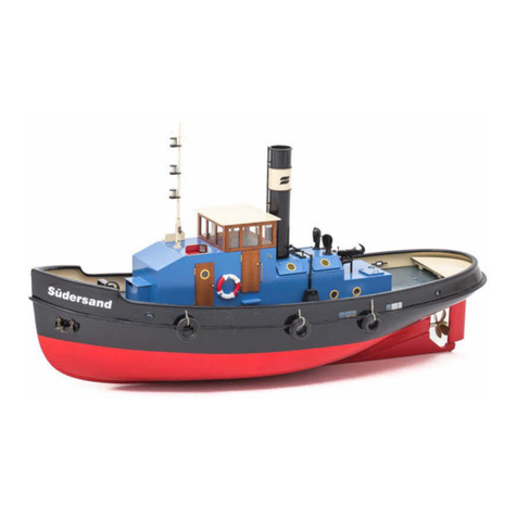
Aeronaut Rambotator User manual

Order No. 3048/00
This model is not a toy. If a young
person under 14 years is to build and
operate it, a responsible adult must
supervise the activity.
Introduction:
The model should be assembled following the sequence of the part numbers. These instructions are arranged by
stages in the correct order.
You may need to use a thin modelling knife to release the laser-cut parts from the sheets by cutting through on the
reverse side. The dark edges of the laser-cut parts should also be rubbed off using abrasive paper or a sanding pad
in order to obtain sound glued joints.
Check that all components fit accurately before reaching for the glue, and carry out any minor trimming required.
Allow all glued joints to dry out fully before starting the next stage of construction. We recommend a fast-setting
waterproof white glue for all joints.
We recommend that you apply a coat of sanding sealer (Order No. 7666/02) to all the wooden components and
sand the surfaces smooth before painting them.
We recommend our aero-pick
modelling pins, Order No. 7855/02, to
hold parts together when building the
model.
Tip: the laser-cut sheets include a large quantity of excess
material which is not required for building the model. It is a
good idea to place this material to one side, as it can be
used later to make handles, latches, fuel filler stubs and
similar, which help to give your model a livelier
appearance.
RC functions Rudder
Forward / reverse
Optional Lighting system
Specification
Length 455 mm
Beam 200 mm
Overall height 395 mm
RC Min. two channels
Motor Race 600 (7124/21)
Servo Standard
Battery 6 V lead-acid, 7.2 V NiXX
or 7.4 V LiXX
7
2
1
33
1
5
6
4
8
5
17 mm
22 mm
1
1
11
8
3
7
1
33
1
2
3
4
5
Glue the deck beams (1) to the deck
reinforcement (2).
Glue the hull sides (3) to the
deck reinforcement.
Glue all the hull bottom beams (1) in
place as shown.
Check that all the parts are at right-
angles to each other before leaving the
glue to set hard.
Caution:
The slots for the servo plate are
located 22 mm below deck level.
Glue the corner fillets (5 + 6) in place.
Glue the transom (4) and the bow plate (8) to the corner
fillets (5 + 6) and the hull sides (3).
Sand the front edge of the hull bottom (7) to a chamfer so that it fits in the
angle between the bow plate (8) and the bottom beam (1) as shown. Starting
at the bow (8), glue the hull bottom (7) to the hull sides and the bottom
beams. Round off the edges of the hull sides with abrasive paper.
11
13 12
10
9
7
11
14
15 16
7
17 18
18
18.1
18.2
6
7
8
9
Use the shaft coupling to connect the propeller shaft to the motor shaft.
Attach your preferred connectors to the power wires, then solder the
wires and capacitors to the motor terminals. Screw the motor plate (11)
to the motor.
Glue the wedge (10) to the underside of the hull bottom (7). Fit the prepared motor assembly through the slot in the
hull bottom (7) from the inside, then fit the shaft support (9) through the bottom (7) from the outside, sliding it into
the slot in the motor mount (11). You may need to trim the shaft opening slightly.
Caution: check that the motor and shaft rotate freely and smoothly, and make any adjustments required to the
openings in the hull bottom and the bottom edge of the motor mount.
Glue the servo mount (14 + 15) to the hull
bottom and the transom. Lightly sand the
joint surfaces of the rudder bush (16) to
provide a key for the glue, then insert the
bush through the holes in the hull bottom (7)
and the servo mount (14). Leave about 1
mm of the bush protruding on the underside
to allow a fillet of resin to be applied, and
glue it in place permanently. It is also
possible to apply glue from above through
the annular openings in the servo mount
(14).
Roughen one end of the rudder shaft (17) over a length of 40 mm,
and glue parts (18, 18.1 + 18.2) to the shaft using two-pack
adhesive. Sand the rudder to a streamlined profile when the glue
has set hard.
22
84
83
83
26
25
25
21
20
23
23
24
85
85
10
11
12
Glue three strips of adhesive tape to the outside edges of the top face
of the deck (22), overlapping all round as shown. Lay the deck on a flat
surface with the adhesive tape on the underside, and glue the three
rubbing strakes (83 + 84) to the edges. The top surface of the deck
should be completely flat, with the strakes projecting on the underside
by 1 mm, forming a shoulder for the glued joints. Round off the corners
of the rubbing strakes.
Glue the coaming components (25 + 26) which form the
wheelhouse base to the inside edges of the doubler (21);
repeat the procedure with the hatch coaming (23 + 24) and
the hatch doubler (20).
Caution: the hatch coaming is designed to be a very tight fit,
as it has to support the superstructure. It is a good idea to
sand the top of the coaming to a slight taper once the glue
has set hard.
Insert the prepared assemblies through the deck from the underside, and glue the
doublers in place over their full area.
The two bollards (85) can now be glued to the deck, applying adhesive to the
underside; the bollards should project through the deck by about 4 - 5 mm.
Reinforce the joints with a fillet of glue round each one on the underside, as this
area is subject to severe stress during towing operations.
1
11
13
14
Now glue the three remaining deck beams (1) in the notches in the hull.
At this stage the whole of the hull and deck should be given two coats of sanding sealer.
Install the motor in the hull, and cover it to protect it from soiling.
The deck can now be attached to the hull: apply plenty of glue to all the joint surfaces of the hull and deck beams,
and place the deck in position. Fix the parts together temporarily using strips of adhesive tape. Turn the hull over
and leave it inverted until the glue has set hard; you will need to use packing pieces to provide clearance for the
bollards.
When the glue is dry, give the outside of the hull two or three coats of sanding sealer, rubbing down between coats.
30
30.2
31
31
32
32
30.1
89
29
28
28
27
27
33
33
33
33
33
33
35
15
16
17
34
34
36
37
Assemble the rear hatch components (27, 28, 29)
and glue the joints.
Assemble the parts of the engine room (30, 31,
32, 30.1) and glue the joints, taking care to
position the roof (32) correctly; note the location
of the holes (see arrows).
Remove any rough edges from the inside edges
of the engine room side panels (30, 31), as this
guarantees a firm seating, and makes it easier to
fit and remove the whole wheelhouse. Glue the
portholes (88) in place as shown.
Prime and paint this assembly.
Bulwark
Insert the bulwark stanchions (33) in the slots in the deck, but do not glue them. Glue the stern bulwark 35 to the
bulwark stanchions. Glue the side bulwarks (34) to part (35) at the stern as well as to the side stanchions (33). Sand
the corner fillets to fit, and glue them in place as shown. When the glue is dry, sand the corners of the bulwark to a
rounded shape. Finally glue the handrail on top.
The bulwark can now be painted.
38
39
40
88
87
44
46
41
45
45.1
43
43.1
42 42
47
49R
48
53
50L
52
51
59
60
61
61
62
63
64
65
59
66
67
68
70
76
77
78
18
19
20
21
22
90 57
55
56
53
54
58
Assemble the return pulleys as shown in the picture.
Allow the glue to dry and paint them before gluing
them in the holes in the deck.
Assemble the dolphin posts as shown
in the picture, then prime and paint
the surfaces before gluing them in the
slots in the deck.
Assemble the wheelhouse side walls (48 -
51) and the window (52) around the
wheelhouse floor (47), installing the
instrument board (53) at the same time.
Prime and paint this assembly.
Assemble the instruments as shown in the drawing, paint them,
and install them once the wheelhouse has been painted.
After painting the wheelhouse, glue the door in place; the door
hinges can be cut from lengths of brass rod. Trim the roof
reinforcement (59) to fit, but do not glue it in place.
Glue the side fairings (61 - 63) round the roof (60), and glue the
reinforcement (59) to the underside of the roof.
Assemble the navigation lamp brackets
from parts 64 and 65; they should be
glued together before they are fixed to
the roof. Note that the lamp brackets are
handed (different right and left).
Paint the roof at this stage: note that the
inside of the lamp brackets should be
black.
Assemble the lamps from parts (76 - 78),
and glue them to the lamp brackets (64
+ 65).
76
77
78
74
75
72
73
69
70
71+67
79
81
80
46
93
124
248
23
24
Thread the railing stanchions (79) onto the lower rails (80) and the handrail
(81), bending all three rails at the same time. Insert the railing stanchions in
the holes in the engine room roof. Position the railing components carefully
before gluing the rails to the stanchions.
Allow these assemblies to dry before removing and painting them
The mast (72)
If you wish to fit working lights, drill 2 mm Ø holes in the mast below the lamp brackets for
the wires to pass through.
Glue the platform supports (75) and the lamp platforms (74) to the mast at the locations
shown in the illustration.
The mast can now be painted.
Paint the upper and lower parts of the lamps (76 + 77) black.
When the paint is dry, glue the clear lenses (78) between them.
When the mast is complete, slip it through the holes in the wheelhouse roof, the floor and
the engine room deck, and secure it by fitting the collet (73) at the bottom.
The wheelhouse as a whole is prevented from rotating by the railings, and is held in position
by the mast collet. If you wish, the wheelhouse can be secured with a small woodscrew
fitted from the underside.
25
94
86
All the windows (95) can now be
installed, and the screen wiper (94)
fitted.
30
17
82
26
82
16 27
16
82
19
9
28
29 19
92
93
Install the steering servo. Push a piece of silicone tubing (82)
about 10 mm long onto the rudder bush (16) where it projects
at the top.
Push a piece of silicone tubing
(82) about 10 mm long onto the
rudder shaft (17).
Fit the propeller (not included in the kit) on the propeller shaft, and secure it by tightening the locknut. Slip the rudder
into the rudder bush (16), carefully pushing the shaft support (9) to one side to allow this. Fit the tiller (19) on the top
end of the rudder shaft. Push the parts together so that they are under light tension, then tighten the screw which
fixes the tiller (19) to the shaft. This holds the rudder in the correct position and at the same time provides a
waterproof seal.
Bend the rudder pushrod (93) to
shape and connect it to the servo
output arm and the tiller. Push the
plastic keepers (92) onto the pushrod
(93) to hold it in place.
The receiver and speed controller can be fixed to the inside of the hull using Velcro (hook-and-loop) tape. The
position of the battery varies according to the type of use you envisage for the boat.
Stick the strip of Velcro tape to the hull floor forward of the motor to secure the battery.
If you wish to use the model as a pusher (springer) tug, you will need to add ballast to trim the vessel correctly.
Ensure that the shaft tube is always lubricated with oil or grease.
Remove the battery from the model when it is not in use.
Have fun running your model!
Nr. Bezeichnung Anzahl Platte Nr. Material/ Abmessung
1 Deck- und Bodenbalken 12 Kieferleiste 5 x 5 x 200mm
2 Deckverstärkung vorne 1 3 Laserteil, Sperrholz. 2mm
3 Seitenteile 2 2 Laserteil, Sperrholz. 2mm
4 Heckspiegel 1 3 Laserteil, Sperrholz. 2mm
5 Eckverstärkung hinten 2 6 x 6 x 33mm Dreikantleiste
6 Eckverstärkung vorn 2 6 x 6 x 20mm Dreikantleiste
7 Bodenplatte 1 4 Laserteil, Sperrholz. 1,5mm
8 Bugplatte 1 3 Laserteil, Sperrholz. 2mm
9 Wellenträger 1 5 Laserteil, Sperrholz. 4,0mm
10 Wellenkeil 1 5 Laserteil, Sperrholz. 4,0mm
11 Motorträger 1 5 Laserteil, Sperrholz. 4,0mm
12 Stevenwelle 1 1 Fertigteil
13 Kupplung 1 1 3,17 x 4mm Fertigteil
14 Servoträger 1 2 Laserteil, Sperrholz. 2mm
15 Halteplatte 1 2 Laserteil, Sperrholz. 2mm
16 Ruderkoker 1 MS-Rohr 4,0 x 3,2 x 30mm
17 Ruderwelle 1 MS-Draht 3 x 95mm
18 Ruder 2 4 Laserteil, Sperrholz. 1,5mm
18.1 Ruder 2 4 Laserteil, Sperrholz. 2mm
18.2 Ruder 2 4 Laserteil, Sperrholz. 2mm
19 Ruderhebel 1 Fertigteil
20 Deckverstärkung Luke 1 3 Laserteil, Sperrholz. 2mm
21 Deckverstärkung Steuerhaus 1 2 Laserteil, Sperrholz. 2mm
22 Deck 1 1 Laserteil, Sperrholz. 2mm
23 Lukensüll seitlich 2 3 Laserteil, Sperrholz. 2mm
24 Lukensüll vorn/hinten 2 3 Laserteil, Sperrholz. 2mm
25 Maschinenhaussüll Seite 2 3 Laserteil, Sperrholz. 2mm
26 Maschinenhaussüll vorn/hinten 2 3 Laserteil, Sperrholz. 2mm
27 Luke vorn/hinten 2 3 Laserteil, Sperrholz. 2mm
28 Luke seitlich 2 3 Laserteil, Sperrholz. 2mm
29 Deckel 1 3 Laserteil, Sperrholz. 2mm
30 Maschinenhaus vorn 1 1 Laserteil, Sperrholz. 2mm
30.1 Stufe 1 1 Laserteil, Sperrholz. 2mm
30.2 Maschinenhaus hinten 1 3 Laserteil, Sperrholz, 2mm
31 Maschinenhaus seitlich 2 1 Laserteil, Sperrholz. 2mm
32 Deckel 1 1 Laserteil, Sperrholz. 2mm
33 Schanzkleidstützen 12 2, 3 Laserteil, Sperrholz. 2mm
34 Schanzkleid Seite 2 4 Laserteil, Sperrholz. 1,5mm
35 Schanzkleid hinten 1 4 Laserteil, Sperrholz. 1,5mm
36 Eckverstärkungen 2 6 x 6 x 30 Dreikantleiste
37 Handlauf 1 4 Laserteil, Sperrholz. 1,5mm
38 Rollenhalter unten 2 5 Laserteil, Sperrholz. 4,0mm
39 Bügel 4 4 Laserteil, Sperrholz. 1,5mm
40 Rollenhalter oben 2 5 Laserteil, Sperrholz. 4,0mm
41 Schubdalben Seite 4 1 Laserteil, Sperrholz. 2mm
42 Schubdalben Verstärkung 4 4 Laserteil, Sperrholz. 1,5mm
43 Schubdalben innen 2 4 Laserteil, Sperrholz. 1,5mm
43.1 Schubdalben innen 2 4 Laserteil, Sperrholz. 1,5mm
44 Schubdalben hinten 2 1 Laserteil, Sperrholz. 2mm
45 Schubdalben oben 2 1 Laserteil, Sperrholz. 2mm
45.1 Schubdalben unten 2 1 Laserteil, Sperrholz, 2mm
46 Schubdalben Lager 2 1 MS Rohr 4,0 x 3.2 x 21, ablängen
47 Steuerhausboden 1 3 Laserteil, Sperrholz. 2mm
48 Steuerhaus hinten 1 3 Laserteil, Sperrholz. 2mm
49 Steuerhausseite rechts 1 3 Laserteil, Sperrholz. 2mm
50 Steuerhausseite links 1 3 Laserteil, Sperrholz. 2mm
Nr,. Bezeichnung Anzahl Platte Nr. Material/ Abmessung
51 Steuerhausseite vorn 1 3 Laserteil, Sperrholz. 2mm
52 Steuerhaus Frontfenster 1 2 Laserteil, Sperrholz. 2mm
53 Armaturenträger 1 3 Laserteil, Sperrholz. 2mm
54 Steuerradhalter 1 Rundholz Buche Ø 10 x 15mm
55 Fahrhebelgehäuse 1 Rundholz Buche Ø 10 x 10mm
56 Fahrhebel 1 MS-Draht Ø 1,2 x 25mm
57 Bildschirm 2tlg. 4 Laserteil, Sperrholz. 1,5mm
58 Kontrollleuchten 4 3mm LED, nicht im Bausatz enthalten.
59 Steuerhaus Dachverstärkung 1 3 Laserteil, Sperrholz. 2mm
60 Steuerhaus Dach 1 3 Laserteil, Sperrholz. 2mm
61 Dachverkleidung seite 2 3 Laserteil, Sperrholz. 2mm
62 Dachverkleidung vorn 1 3 Laserteil, Sperrholz. 2mm
63 Dachverkleidung hinten 1 3 Laserteil, Sperrholz. 2mm
64 Lampenbord rechts 3tlg. 4 Laserteil, Sperrholz. 1,5mm
65 Lampenbord links 3tlg. 4 Laserteil, Sperrholz. 1,5mm
66 Tür 1 3 Laserteil, Sperrholz. 2mm
67 Bolzen 2 MS-Rohr, 3,0 x 0,7 x 8mm, ablängen
68 Türdrücker 2 4 Laserteil, Sperrholz. 1,5mm
69 Maschinenraumluke 1 2 Laserteil, Sperrholz. 2mm
70 Scharnier 2 MS-Rohr, 3,0 x 0,7 x 8mm, ablängen
71 Hebel 2 4 Laserteil, Sperrholz. 1,5mm
72 Mast 1 MS-Rohr, 5,0 x 0,7 x 280mm, ablängen
73 Stellring 1 Ø 5,1mm
74 Lampenträger 4 4 Laserteil, Sperrholz. 1,5mm
75 Stütze 4 4 Laserteil, Sperrholz. 1,5mm
76 Lampenunterteil 6 3 Laserteil, Sperrholz 2mm
77 Lampenoberteil 6 3 Laserteil, Sperrholz 2mm
78 Lampenglas 6 Plexiglas 5mmm
79 Relingstützen 9 3 Laserteil, Sperrholz 2mm
80 Relingdurchzug 2 MS-Draht Ø 1,0 x 500mm, ablängen, biegen
81 Relinghandlauf 1 MS-Draht Ø 1,2 x 500mm, ablängen, biegen
82 Silikonschauch 1 3x7x50mm (7274/57)
83 Scheuerleiste seitlich 2 3x3x650, Kiefer
84 Scheuerleiste hinten 1 3x3x200, Kiefer
85 Einzelpoller 1 Fertigteil 5440/55
86 Doppelpoller 4 Fertigteil, 5441/43
87 Rolle 2 Fertigteil (aus 5847/11)
88 Welle 2 MS-Draht Ø 1,5 x 30mm, ablängen
89 Bullaugen 4 Fertigteil, 5760/14
90 Steuerrad 1 Fertigteil, 30mm 5654/30
91 Bauanleitung 1
92 Sicherungsclip 1 Fertigteil, 7489/07
93 Schubstange 1 1,5 x 100mm Eisendraht verz,
94 Scheibenwischer 2tlg. 4 Laserteil, Sperrholz. 1,5mm
95 Fenster

Other Aeronaut Toy manuals
Aeronaut Manta A 02 User manual

Aeronaut

Aeronaut Manta A 02 User manual

Aeronaut 3033/00 User manual

Aeronaut

Aeronaut 3033/00 User manual

Aeronaut Kalle 2 User manual

Aeronaut

Aeronaut Kalle 2 User manual

Aeronaut Scarlet Instruction Manual

Aeronaut

Aeronaut Scarlet Instruction Manual

Aeronaut Lilienthal 40 R User manual

Aeronaut

Aeronaut Lilienthal 40 R User manual

Aeronaut Luscombe Silvaire 8 User manual

Aeronaut

Aeronaut Luscombe Silvaire 8 User manual

Aeronaut Ramboline User manual

Aeronaut

Aeronaut Ramboline User manual

Aeronaut LT 200 Flex User manual

Aeronaut

Aeronaut LT 200 Flex User manual

Aeronaut Bellissima User manual

Aeronaut

Aeronaut Bellissima User manual

Aeronaut Twinspeedy User manual

Aeronaut

Aeronaut Twinspeedy User manual

Aeronaut SkyMAXX User manual

Aeronaut

Aeronaut SkyMAXX User manual

Aeronaut Quido User manual

Aeronaut

Aeronaut Quido User manual

Aeronaut Premiant II Instruction Manual

Aeronaut

Aeronaut Premiant II Instruction Manual

Aeronaut Turbo-fan 4000 Product information sheet

Aeronaut

Aeronaut Turbo-fan 4000 Product information sheet

Aeronaut Clipper Instruction Manual

Aeronaut

Aeronaut Clipper Instruction Manual

Aeronaut Dassault Breguet Rafale C 01 Instruction Manual

Aeronaut

Aeronaut Dassault Breguet Rafale C 01 Instruction Manual

Aeronaut Galaxy Instruction Manual

Aeronaut

Aeronaut Galaxy Instruction Manual

Aeronaut Foxx User manual

Aeronaut

Aeronaut Foxx User manual

Aeronaut 3092/00 Instruction Manual

Aeronaut

Aeronaut 3092/00 Instruction Manual

Aeronaut Xenon RC Instruction Manual

Aeronaut

Aeronaut Xenon RC Instruction Manual

Aeronaut TRIPLE SPEED R.E.S. THERMIC User manual
Aeronaut

Aeronaut TRIPLE SPEED R.E.S. THERMIC User manual

Aeronaut Grumman F7 F-3 Tigercat Instruction Manual

Aeronaut

Aeronaut Grumman F7 F-3 Tigercat Instruction Manual

Aeronaut PEPPER User manual

Aeronaut

Aeronaut PEPPER User manual

Aeronaut Victoria User manual

Aeronaut

Aeronaut Victoria User manual

Popular Toy manuals by other brands
PLAYTIVE JUNIOR AROUND THE WORLD ADVENTURE Instructions for use

PLAYTIVE JUNIOR

PLAYTIVE JUNIOR AROUND THE WORLD ADVENTURE Instructions for use

V-tech KidiCom Advance 3.0 Parents' guide

V-tech

V-tech KidiCom Advance 3.0 Parents' guide

Sebart Avanti S XXL instruction manual

Sebart

Sebart Avanti S XXL instruction manual

Step 2 LIVING Pioneer Patio Rocker 5217 quick start guide

Step 2

Step 2 LIVING Pioneer Patio Rocker 5217 quick start guide

esky Honey Bee King II instruction manual

esky

esky Honey Bee King II instruction manual

Spinmaster AIR HOGS The Amazing Spider-Man Striker 3 Assembly Instructions & Flight Manual

Spinmaster

Spinmaster AIR HOGS The Amazing Spider-Man Striker 3 Assembly Instructions & Flight Manual

V-tech Go! Go! Smart Wheels Ramp It Up Dump Truck Parents' guide

V-tech

V-tech Go! Go! Smart Wheels Ramp It Up Dump Truck Parents' guide

KNEX Vertical Vengeance Coaster Bonus Ride instruction manual

KNEX

KNEX Vertical Vengeance Coaster Bonus Ride instruction manual

Techone MXS-HCF instruction manual

Techone

Techone MXS-HCF instruction manual

V-tech Switch & Go Dino - Blister the Velociraptor user manual

V-tech

V-tech Switch & Go Dino - Blister the Velociraptor user manual

V-tech Switch & Go Dinos - Torr the Therizinosaurus user manual

V-tech

V-tech Switch & Go Dinos - Torr the Therizinosaurus user manual

V-tech Winnie The Pooh Play  n Learn Spinning Top user manual

V-tech

V-tech Winnie The Pooh Play n Learn Spinning Top user manual

AUTO GYRO MTO SPORT Pilot operating handbook

AUTO GYRO

AUTO GYRO MTO SPORT Pilot operating handbook

Techone Sukhoi EPP instruction manual

Techone

Techone Sukhoi EPP instruction manual

Sky Master F-14 Tomcat PRO ARF Plus Assembly and operation manual

Sky Master

Sky Master F-14 Tomcat PRO ARF Plus Assembly and operation manual

V-tech Switch & Go Dinos Seeker the T-Rex Parents' guide

V-tech

V-tech Switch & Go Dinos Seeker the T-Rex Parents' guide

Air Hogs Havoc Stinger user manual

Air Hogs

Air Hogs Havoc Stinger user manual

KID Trax S owner's manual

KID Trax

KID Trax S owner's manual

manuals.online logo
manuals.online logoBrands
  • About & Mission
  • Contact us
  • Privacy Policy
  • Terms and Conditions

Copyright 2025 Manuals.Online. All Rights Reserved.