BLUE MOUNTAIN FANS 52 Azure User manual

1
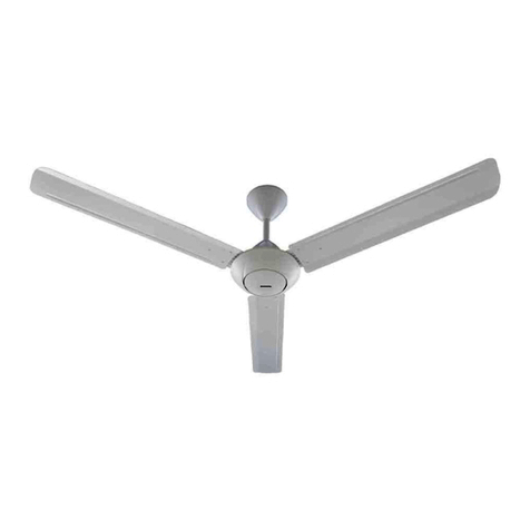
52” Azure
Ceiling Fan
Owner’s Manual
Model #21901/21902

SAFETY INSTRUCTIONS
1
WARNING:
•To avoid risk of electrical shock, be sure to shut off power at the main fuse or circuit breaker
panel box before installing or servicing this fixture. Turning off the electrical power by using the
light switch only is not sufficient to prevent electrical shock hazard.
•To reduce the risk of injury, install the fan so that the blades are at least 7 feet (2.1 meters)
above the floor and at least 20 inches (0.5 meters) from the tip of the blades to the wall.
•To reduce the risk of fire, electric shock, or personal injury, mount to outlet box marked
“acceptable for fan support up to 35 lbs. (16 kg)” and use mounting screws provided with the
outlet box.
•All wiring must be in accordance with the National Electrical Code ANSI/NFPA 70 and any
applicable local codes. Electrical installation should be performed by a qualified licensed
electrician.
•To reduce the risk of fire or electric shock, do not use this fan with any solid-state speed control
device.
CAUTION:
•Check and retighten all screws, nuts, and bolts to insure they are secured prior to operating the
fan.
•Do not bend the blade iron brackets when installing the brackets, balancing the blades, or
cleaning the fan. Do not insert foreign objects in between rotating fan blades.
•Be sure outlet box is properly grounded and that a ground wire (green or bare) is present.
•When changing (reversing) the blade direction, turn off the fan and wait for the fan blades to
stop completely.
•To reduce the risk of serious bodily injury, do not use power tools to assemble any part of the
fan, including the blades.
•To reduce the risk of personal injury, use only parts provided with this fan. The use of parts
other than those provided with this fan will void the warranty.
•Do not use water or detergents when cleaning the fan or fan blades. A dry dust cloth or lightly
dampened cloth is recommended to prevent scratching and will be suitable for most cleaning.
•In case this fan needs to be returned to the factory for repairs, it must be shipped in its original
carton and foam inserts to insure proper protection against shipping damage that may exceed
the initial cause for return.
•Please read and understand these safety instructions and the installation guide before
attempting to assemble, install, or operate the fan.

2
PACKAGE CONTENTS
PART
DESCRIPTION
QUANTITY
PART
DESCRIPTION
QUANTITY
A
Downrod
1
H
Hardware Kit
1
B
Canopy
1
I
Installation Manual
1
C
Mounting Bracket
1
J
Pin (preassembled)
1
D
Motor Housing
1
K
Clip (preassembled)
1
E
Blade
5
L
Switch Housing Cover
1
F
Blade Arm
5
M
Blade Screw
15
G
Motor Screw (preassembled)
10
N
Fiber Blade Washer
15
O
Canopy Mounting Screw
(preassembled)
2
IMPORTANT REMINDER: You must use the parts provided
with this fan for proper installation and safety.
HARDWARE KIT
OWNER’S MANUAL
A
E
G
I
B
H
D
C
K
L
J
F
M
N
B
O

3
HARDWARE KIT CONTENTS
NOTE: For your convenience some extra hardware may be included. The quantity listed
above is the number required for installation.
Tools required for assembly: Step Ladder, Phillips Screwdriver, Wire Strippers, Safety
Glasses, Pliers, and Electrical Tape.
Helpful Tools: AC Tester Light/Multimeter, Tape Measure, and Wiring Handbook
PART
DESCRIPTION
QUANTITY
AA
Wire Connector
3
BB
Blade Screws
15
CC
Fiber Blade Washers
15
DD
Pull Chain Extension
1
EE
Balance Kit
1
FF
Machine Screws
2
GG
Wood Screws
2
TOOLS REQUIRED (not included)
AA
BB
CC
EE
DD
FF
GG

4
DIMENSION REFERENCE
A: 12.2 in. B: 10.9 in. C: 11.1 in. D: 5.8 in.
Choose one of the following mounting options:
Downrod Mount is best suited for ceilings 8 ft. or higher. For taller ceilings you may
want to use a longer downrod (sold separately).
Angled Ceiling Mount is best suited for angled or vaulted ceilings. A longer downrod is
sometimes necessary to ensure proper blade clearance from the ceiling. If using the
angled mount, check to ensure that the ceiling angle is not steeper than 15 degrees.
NOTE: Make sure blades are at least 30 inches from any wall or obstruction and at least
7 feet above the floor.
A
B
N
C
Downrod Mount
Angled Mount
D
15⁰Max.

5
ASSEMBLY INSTRUCTIONS
1. Turn OFF the electrical power at the
main fuse or circuit breakers.
NOTE: Before continuing installation,
confirm that the power is still turned off
at the main circuit breaker or by
removing the correct fuse. Turning the
power off using a wall switch is not
sufficient to prevent electrical shock.
2. Secure the mounting bracket to the
outlet box (not included) using the
screws and washers provided with the
outlet box.
WARNING: To reduce the risk of fire
electrical shock, or personal injury,
mount to the outlet box marked
“acceptable for fan support” using the
mounting screws and washers provided
with the outlet box.
3. DOWNROD MOUNT –Remove the
downrod pin and downrod clip from
the downrod. Then loosen but do not
remove the two set screws in the
yoke. Set screws need to be loosened
enough to fully insert the downrod.
1
2
3
Downrod Clip
Yoke
Downrod Pin
Downrod
Set Screw

6
ASSEMBLY INSTRUCTIONS
4. Feed the wires coming from the yoke
through the canopy and downrod.
5. Insert the downrod into the yoke and
reinstall the downrod pin and
downrod clip. Then re-tighten the
two set screws.
NOTE: With wiring extending out of the
downrod, measure 8 inches of lead wire
and cut the excess wire with wire cutters.
Then strip ½” of insulation from the end
of each wire.
6. Lift the downrod into the mounting
bracket. Rotate the downrod until
the tab in the mounting bracket is
seated in the slot in the downrod ball.
WARNING: The fan and/or downrod
should not rotate in the mounting
bracket if installed correctly. Failure to
align the slot in the downrod ball with
the tab may result in fan falling causing
serious injury or death.
4
5
6
Slot
Tab

7
ASSEMBLY INSTRUCTIONS
Black
7. Use the supplied wire connectors to
connect the fan wires to the power
supply wires according to the wiring
diagram and following instructions:
•Connect the white wire from the fan
to the white (neutral) supply wire.
•Connect the black and blue wires
from the fan to the black (hot) supply
wire.
•Connect the green wire from the
downrod and the mounting bracket to
bare/green (ground) supply wire.
IMPORTANT: After the connections have
been made, the wire should be turned
upward and pushed carefully up into the
outlet box. Place the black and white
wire connections on opposite sides of
the outlet box.
8. Locate the (2) screws on underside of
hanging bracket and loosen screws.
Place rounded part of slotted hole in
canopy over the loosened screws in
hanging bracket and push up. Twist
canopy to lock. Tighten screws
securely.
8
White
Green
7
Blue

8
ASSEMBLY INSTRUCTIONS
9. Remove the five motor blocks and
five motor screws from the underside
of the motor. Discard the motor
blocks but keep the motor screws for
installation of the blade arms.
NOTE: Use the cut-out in the switch
housing plate for easy accessibility to
motor screws.
10.Partially insert three blade screws,
along with the blade washers,
through the blade and into the blade
arm, tighten each screw blade screw,
starting with the one in the middle.
Repeat this step for the remaining
blades and blade arms.
11.Secure the blade arm to the
underside of the motor using the
motor screws removed in Step 10.
Secure each blade arm to motor
before moving to the next.
NOTE: Use the cut-out in the switch
housing plate for easy accessibility to
motor screw holes.
10
11
Blade Screw
Blade Washer
Motor Screw
9

9
ASSEMBLY INSTRUCTIONS
12. While holding the switch housing
cover under your ceiling fan, be sure
all wires and switch housing
components are safely tucked inside
the housing and will not be pinched
by the switch housing cover. Attach
the switch housing cover using the (3)
screws pre-installed in the switch
housing. Make sure each screw is
secure.
13.Attach the pull chain extension to the
pull chain.
14.Restore the power to the main fuse or
circuit breaker.
14
12
13
Pull Chain Extension

10
OPERATING INSTRUCTIONS
Use the fan reverse switch, located on
the switch housing to optimize your
fan for seasonal performance. Using
a ceiling fan will allow you to raise
your thermostat setting in summer
and lower your thermostat setting in
winter without feeling a difference in
your comfort.
In warmer weather, move the reverse
switch to the left which will result in
downward airflow creating a wind
chill effect.
In cooler weather, move the reverse
switch to the right which will result in
upward flow that can help move
stagnant, hot air off the ceiling area.
IMPORTANT: Wait for fan to stop
before moving the reverse switch.
The reverse switch must be set either
completely to the left or right for the
fan to function correctly. If the
reverse switch is set in the middle
position, the fan will not operate.
Reverse Switch

11
TROUBLESHOOTING
FAN DOES NOT START:
•Check the circuit breaker and confirm the power is ON.
•Make sure wall switch is ON.
•Pull the pull chain to make sure it is on. Typical pull chain operation is 1st pull –high speed, 2nd
pull –medium speed, 3rd pull –low speed, 4th pull OFF.
•Check that the motor reversing switch is correctly engaged and set to left or right position. Fan
will not run if switch is in the middle.
•Confirm that the blades spin freely and that there are no obstructions between the blades or
into the motor housing. Turn off power at circuit breaker and at wall switch, loosen the canopy,
and check that all wiring connections from the household supply wires to the fan wires are
secure.
FAN IS NOISY:
•Make sure all screws are snug and secure including blade screws into the blade irons, blade
irons onto the motor, and screws on canopy and switch housing cover.
•Make sure all blades and blade irons are properly installed.
•Some ceiling fan motors are sensitive to solid state variable speed controls. If the fan is
controlled by these types of controls remove the control and replace with a control specifically
designed for use with ceiling fans.
FAN WOBBLES:
•Make sure fan mounting bracket is securely tightened to the ceiling outlet box and the ceiling
box is securely fastened to the ceiling joist or other adequate support structure.
•Confirm that the hanger ball is properly seated in the mounting bracket. The tab in the
mounting bracket should be seated in the slot in the downrod ball.
•Make sure all blades are installed correctly and all screws are secure. Also confirm that the two
set screws in the downrod are tight in the yoke.
•Balance the fan blades using the blade balancing kit included with the fan.
WARNING: Before beginning any troubleshooting or maintenance work always shut off the
power supply to avoid electrical shock hazard.

LIMITED LIFETIME WARRANTY
12
This limited lifetime warranty covers the ceiling fan from the date of purchase, for residential use by
the original purchaser, against defects in material and/or workmanship as follows:
Motor Limited Lifetime Warranty: If the ceiling fan motor fails during the ownership of the fan due to a
defect in material or workmanship, as determined solely by Blue Mountain Fans, a replacement fan will
be provided at no charge. If no replacement product or part can be provided, then we will provide a
comparable fan or part at the sole discretion of Blue Mountain Fans. This limited lifetime motor
warranty applies only to the motor itself and does not apply to electronic controls (remote control
transmitters, remote control receivers, or capacitors) used in conjunction with the motor. The
aforementioned electronic items are covered under the one-year warranty below.
One Year Warranty on all other parts: Except as otherwise indicated throughout this warranty, if any
part of your Blue Mountain ceiling fan fails at any time within one year of the date of purchase due to a
defect in material or workmanship and as solely determined by Blue Mountain Fans, a replacement
part will be provided at no charge.
Glass globes, light bulbs, remote control batteries, ordinary wear and tear, and fans that are damaged
by improper installation, mishandling, modifications, or damage to the fan while in your possession, or
unreasonable use including failure to provide necessary maintenance are not covered under this
warranty. This warranty does not cover any costs or fees associated with the labor required to install,
remove, or replace a fan or any fan parts, including electrician fees or labor charges.
Any replacement of defective parts for the ceiling fan must be reported within the first year from date
of purchase. Original purchaser must present a sales receipt or other document that establishes proof
of purchase. To obtain service please contact Blue Mountain Fans Customer Service online or by phone
as noted below. Do not attempt to ship your fan or any parts to Blue Mountain Fans without prior
written approval as otherwise your delivery will be refused. Blue Mountain Fans shall not be liable for
any incidental, consequential or special damages arising at or in connection with product use or
performance except as may otherwise be accorded by law. This warranty gives you specific legal rights
and you may also have other rights which vary from state to state. This warranty supersedes all prior
warranties.
Blue Mountain Fans Customer Service:
1-770-486-2000 [email protected]

13
This manual suits for next models
2
Table of contents
Other BLUE MOUNTAIN FANS Fan manuals


