Blue point EEBC100A User manual

0099001760-01
EEBC100A-Z
AUTOMATIC BATTERY CHARGER
EEBC100A
Voltage: 6, 12
Amperage: 6<>2, 40, 200

•2 •
EEBC100A-Z
INTRODUCTION
Thank you for purchasing your new Blue-Point
Battery Charger.
The EEBC100A is an advanced, full featured automatic
wheeled battery charger.
Charges 6 and 12 volt batteries.
Features:
• 6-inch diameter wheels –
allow for easy movement around the shop and lot.
• Retractable handle – for easy storage.
• 200 amp 12 volt Engine Start – for emergency starting
• 40 amp Booster, 6<>2 amp Charger/Maintainer
• Function selector/
ON/OFF switch
• Digital display and push button controls
• 300 amp sure-grip clamps – for top and side mount
battery posts.

•3 •
EEBC100A-Z
Safety Notice
For your safety, read this manual thoroughly before
operating your charger. Your charger is intended for
use by properly trained, skilled professional automotive
technicians. The safety messages presented below
and throughout this user’s manual are reminders to the
operator to exercise care when using this charger.
There are many variations in procedures, techniques,
tools and parts for servicing vehicles, as well as in the
skill of the individual doing the work. Because of the vast
number of applications and variations in the products
that can be tested with this instrument, Snap-on cannot
possibly anticipate or provide advice or safety messages
to cover every situation. It is the automotive technician’s
responsibility to be knowledgeable of the system that
is to be charged. It is essential to use proper service
methods and procedures and to perform charging in
an appropriate and acceptable manner that does not
endanger your safety, the safety of others in the work
area, the vehicle or equipment being charged.
It is assumed that the operator has a thorough
understanding of vehicle battery, charging, and starting
systems before using this charger. This understanding
of principles and operating theories is necessary for
competent, safe and accurate use of this charger.
Before using your charger, always refer to and follow
the safety messages and applicable test procedures
provided by the manufacturer of the vehicle or equipment
being charged.
For Indoor Use.
Read All Instructions
Read, understand and follow all safety messages and
instructions in this manual. Safety messages in this
section of the manual contain a signal word with a three-
part message and, in some instances, an icon.
The signal word indicates the level of the hazard in
a situation.
Indicates an imminently hazardous situation which,
if not avoided, will result in death or serious injury to
the operator or bystanders.
Indicates a potentially hazardous situation which, if
not avoided, could result in death or serious injury to
the operator or bystanders.
Indicates a potentially hazardous situation which, if
not avoided, may result in moderate or minor injury
to the operator or bystanders.
IMPORTANT
Indicates a situation which, if not avoided, may result
in damage to the test equipment or vehicle.
SAVE THESE INSTRUCTIONS

•4 •
EEBC100A-Z
1. IMPORTANT SAFETY INSTRUCTIONS
IMPORTANT: READ AND SAVE THIS SAFETY AND INSTRUCTION MANUAL.
1.1 SAVE THESE INSTRUCTIONS –
This manual contains important safety and operating
instructions for battery charger Model EEBC100A.
RISK OF ELECTRIC SHOCK AND FIRE.
1.2 This charger is not intended for use by children.
1.3 Do not expose the charger to rain or snow.
1.4 Use of an attachment not recommended or sold by the
battery charger manufacturer may result in a risk of re,
electric shock or injury to persons.
1.5 To reduce the risk of damage to electric plug and cord,
pull by the plug rather than the cord when disconnecting
charger.
1.6 An extension cord should not be used unless absolutely
necessary. Use of improper extension cord could result
in a risk of re and electric shock. If an extension cord
must be used, make sure:
• The pins on plug of extension cord are the same
number, size and shape as those of plug on charger.
• The extension cord is properly wired and in good
electrical condition
• The wire size is large enough for AC ampere rating of
charger as specied in section 8.
1.7 Do not operate charger with damaged cord or plug –
replace the cord or plug immediately.
1.8 Do not operate charger if it has received a sharp blow,
been dropped, or otherwise damaged in any way; take it
to a qualied serviceman.
1.9 Do not disassemble charger; take it to a qualied
serviceman when service or repair is required. Incorrect
reassembly may result in a risk of electric shock or re.
1.10 To reduce risk of electric shock, unplug charger from
outlet before attempting any maintenance or cleaning.
Turning off controls will not reduce this risk.
1.11 RISK OF EXPLOSIVE GASES.
a. WORKING IN VICINITY OF A LEAD-ACID
BATTERY IS DANGEROUS. BATTERIES
GENERATE EXPLOSIVE GASES DURING
NORMAL BATTERY OPERATION. FOR THIS
REASON, IT IS OF UTMOST IMPORTANCE THAT
YOU FOLLOW THE INSTRUCTIONS EACH TIME
YOU USE THE CHARGER.
b. To reduce risk of battery explosion, follow these
instructions and those published by battery
manufacturer and manufacturer of any equipment you
intend to use in vicinity of battery. Review cautionary
markings on these products and on engine.
2. PERSONAL SAFETY PRECAUTIONS
RISK OF EXPLOSIVE GASES.
2.1 Consider having someone close enough by to come to
your aid when you work near a lead-acid battery.
2.2 Have plenty of fresh water and soap nearby in case
battery acid contacts skin, clothing, or eyes.
2.3 Wear complete eye protection and clothing protection.
Avoid touching eyes while working near battery.
2.4 If battery acid contacts skin or clothing, wash
immediately with soap and water. If acid enters eye,
immediately ood eye with running cold water for at
least 10 minutes and get medical attention immediately.
2.5 NEVER smoke or allow a spark or ame in vicinity of
battery or engine.
2.6 Be extra cautious to reduce risk of dropping a metal tool
onto battery. It might spark or short-circuit battery or
other electrical part that may cause explosion.
2.7 Remove personal metal items such as rings, bracelets,
necklaces, and watches when working with a lead-acid
battery. A lead-acid battery can produce a short-circuit
current high enough to weld a ring or the like to metal,
causing a severe burn.
2.8 Use charger for charging 6V and 12V LEAD-ACID and
AGM-type rechargeable batteries. It is not intended to
supply power to a low voltage electrical system other
than in a starter-motor application. Do not use battery
charger for charging dry-cell batteries that are commonly
used with home appliances. These batteries may burst
and cause injury to persons and damage to property.
2.9 NEVER charge a frozen battery.

•5 •
EEBC100A-Z
3. PREPARING TO CHARGE
RISK OF CONTACT WITH BATTERY ACID. BATTERY
ACID IS A HIGHLY CORROSIVE SULFURIC ACID.
3.1 If necessary to remove battery from vehicle to charge,
always remove grounded terminal from battery rst.
Make sure all accessories in the vehicle are off, so as
not to cause an arc.
3.2 Be sure area around battery is well ventilated while
battery is being charged.
3.3 Clean battery terminals. Be careful to keep corrosion
from coming in contact with eyes.
3.4 Add distilled water in each cell until battery acid reaches
level specied by battery manufacturer. Do not overll.
For a battery without removable cell caps, such as
valve regulated lead acid batteries, carefully follow
manufacturer’s recharging instructions.
3.5 Study all battery manufacturer’s specic precautions
while charging and recommended rates of charge.
3.6 Determine voltage of battery by refering to the owners
manual and make sure it matches the output rating of
the charger.
4. CHARGER LOCATION
RISK OF EXPLOSION AND CONTACT
WITH BATTERY ACID.
4.1 Locate charger as far away from battery as DC
cables permit.
4.2 Never place charger directly above battery being charged;
gases from battery will corrode and damage charger.
4.3 Never allow battery acid to drip on charger when
reading electrolyte specic gravity or lling battery.
4.4 Do not operate charger in a closed-in area or restrict
ventilation in any way.
4.5 Do not set a battery on top of charger.
5. DC CONNECTION PRECAUTIONS
5.1 Connect and disconnect DC output clips only after setting
any charger switches to “off” position and removing AC
cord from electric outlet. Never allow clips to touch each
other. Clips may be energized and they may spark.
5.2 Attach clips to battery and chassis, as indicated in
sections 6 and 7.
6. FOLLOW THESE STEPS WHEN BATTERY IS INSTALLED IN VEHICLE
A SPARK NEAR THE BATTERY MAY CAUSE A
BATTERY EXPLOSION. TO REDUCE THE RISK OF A
SPARK NEAR THE BATTERY:
6.1 Position AC and DC cords to reduce risk of damage by
hood, door, or moving engine part.
6.2 Stay clear of fan blades, belts, pulleys, and other parts
that can cause injury to persons.
6.3 Check polarity of battery posts. POSITIVE (POS,
P, +) battery post usually has larger diameter than
NEGATIVE (NEG, N,–) post.
6.4 Determine which post of battery is grounded
(connected) to the chassis. If negative post is grounded
to chassis (as in most vehicles), see (6.5). If positive
post is grounded to the chassis, see (6.6).
6.5 For negative-grounded vehicle, connect POSITIVE
(RED) clip from battery charger to POSITIVE (POS, P, +)
ungrounded post of battery. Connect NEGATIVE (BLACK)
clip to vehicle chassis or engine block away from battery.
Do not connect clip to carburetor, fuel lines, or sheet-metal
body parts. Connect to a heavy gauge metal part of the
frame or engine block.
6.6 For positive-grounded vehicle, connect NEGATIVE
(BLACK) clip from battery charger to NEGATIVE (NEG,
N, –) ungrounded post of battery. Connect POSITIVE
(RED) clip to vehicle chassis or engine block away from
battery. Do not connect clip to carburetor, fuel lines,
or sheet-metal body parts. Connect to a heavy gauge
metal part of the frame or engine block.
6.7 When disconnecting charger, turn switches to off,
disconnect AC cord, remove clip from vehicle chassis,
and then remove clip from battery terminal.
6.8 See CALCULATING CHARGE TIMES for length of
charge information.

•6 •
EEBC100A-Z
7. FOLLOW THESE STEPS WHEN BATTERY IS OUTSIDE VEHICLE
A SPARK NEAR THE BATTERY MAY CAUSE A
BATTERY EXPLOSION. TO REDUCE THE RISK OF A
SPARK NEAR THE BATTERY:
7.1 Check polarity of battery posts. POSITIVE (POS, P,
+) battery post usually has a larger diameter than
NEGATIVE (NEG, N, –) post.
7.2 Attach at least a 24-inch-long 6-gauge (AWG) insulated
battery cable to NEGATIVE (NEG, N, –) battery post.
7.3 Connect POSITIVE (RED) charger clip to POSITIVE
(POS, P, +) post of battery.
7.4 Position yourself and free end of cable as far away from
battery as possible – then connect NEGATIVE (BLACK)
charger clip to free end of cable.
7.5 Do not face battery when making nal connection.
7.6 When disconnecting charger, always do so in reverse
sequence of connecting procedure and break rst
connection while as far away from battery as practical.
7.7 A marine (boat) battery must be removed and charged
on shore. To charge it on board requires equipment
specially designed for marine use.
8. GROUNDING AND AC POWER CORD CONNECTIONS
RISK OF ELECTRIC SHOCK AND FIRE.
8.1 This battery charger is for use on a nominal 120 volt
circuit and has a grounded plug. The charger must be
grounded, to reduce the risk of electric shock. The plug
must be plugged into an outlet that is properly installed
and grounded in accordance with all local codes and
ordinances. The plug pins must t the receptacle
(outlet). Do not use with an ungrounded system.
8.2 Never alter the AC cord or plug provided – if it does not
t the outlet, have a proper grounded outlet installed
by a qualied electrician. An improper connection can
result in a risk of an electric shock or electrocution.
8.3 NOTE: Pursuant to Canadian Regulations, use of
an adapter plug is not allowed in Canada. Use of an
adapter plug in the United States is not recommended
and should not be used.
8.4 USING AN EXTENSION CORD
The use of an extension cord is not recommended.
If you must use an extension cord, follow these
guidelines:
• Pins on plug of extension cord must be the same
number, size, and shape as those of plug on charger.
• Ensure that the extension cord is properly wired and
in good electrical condition.
• Wire size must be large enough for the AC ampere
rating of charger, as specied:
Length of cord (feet) 25 50 100 150
AWG* size of cord 14 12 8 8
*AWG-American Wire Gauge

•7 •
EEBC100A-Z
9. FEATURES
1. Charge/Boost-OFF-
Engine Start switch
2. Control panel
3. Battery clamps
4. Retractable handle
5. 6-inch diameter wheels
6. Heavy-duty steel foot
1
3
2
4
5
6
• 8 •
EEBC100A-Z
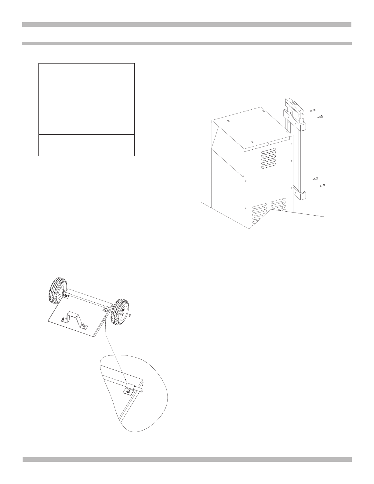
10. ASSEMBLING YOUR CHARGER
It is important to fully assemble your charger before
use. Follow these instructions for easy assembly.
PARTS:
(6) #10-32, thread-cutting screws
(4) ¼-20, thread-cutting screws
(2) wheels
(1) axle
(2) axle E-clips
(2) axle brackets
(1) handle assembly
(1) foot
(2) at washers
TOOLS NEEDED:
3/8˝ wrench (for mounting foot)
5/16˝ wrench (for mounting axle)
10.1 ATTACH THE FOOT: Remove the charger from the
packing materials and place upside down on a at
surface. Attach the foot and secure it with the four ¼-20
thread-cutting screws provided.
10.2 ASSEMBLE THE WHEELS AND AXLE: Install an E-clip
to one end of the axle. Slide one wheel onto the axle with
the recessed hub facing down. Slide both at washers
onto the axle. Slide the other wheel onto the axle with the
recessed hub facing up. Install the other E-clip.
10.3 MOUNT THE AXLE TO THE CHARGER: Place one end
of each axle bracket into the slot on the bottom of the
charger. Separate the wheels and at washers on the
axle so that there is one wheel and one at washer on
each end of the axle assembly. Place the axle assembly
under each axle bracket. Attach the axle brackets, using
the two #10-32 thread-cutting screws provided.
10.4 ATTACH THE HANDLE ASSEMBLY:
Turn the charger right side up onto its foot and wheels.
Attach the handle assembly using four #10-32 thread-
cutting screws provided.
NOTE: To retract or extend the handle assembly, push
in the button on the top of the handle.

•9 •
EEBC100A-Z
11. BATTERY CHARGER CONTROLS
On/Off Switch
Use this switch to select between the Maintain/Charge rate,
Boost rate or the Engine Start mode.
OFF – When the switch is in this position (middle), the
charger is turned off.
Boost or Maintain/Charge – When the switch
is in this position, the Rate Selection button can be set to
either the 6A<>2A Maintain/Charge rate or the 40 amp Boost
setting.
Engine Start – When the switch is in this position, the
Engine Start LED will illuminate and the unit will be in the
200A Engine Start mode.
Digital Display
The Digital Display gives a digital indication of voltage or
amperage. It always starts in Voltage mode, but can be
switched to other mode by pressing the Display button as
shown below:
• Boost mode:
Voltage ˃ Amperes ˃ Voltage…
• Maintain/Charge mode:
Voltage ˃ Amperes ˃ OFF ˃ Voltage…
• Engine Start mode:
Voltage (No Amperes mode)
If the process is stopped on any mode (by pressing the
START/STOP button), the display will show “OFF”.
NOTE: When in Maintain/Charge mode, the display will
automatically go into sleep mode (shut-off) after 2 minutes.
To turn the display back on, press any push-button.
Display Button
Use this button to set the function of the digital display to one
of the following:
A–The display shows the output current, in amps.
V – The display shows the battery voltage.
Start Stop Button
Use this button to start or stop the charging or boosting
process, after the battery is properly connected and an
output or Boost rate has been selected.
Rate Selection Button
When in Maintain/Charge mode, use this button to select one
of the following rates:
Boost 40A – For quickly adding energy to a severely
discharged or large capacity battery.
NOTE: We recommend using BOOST mode prior to ENGINE
START for several minutes.
Maintain/Charge 6A<>2A – For charging small and large
batteries. Not recommended for industrial applications.
LED Indicators
Boost/Charge (yellow/orange) LED lit: The charger
has detected that a battery is connected, and is performing
the selected operation – either Boost or Charge.
Boost/Charge (yellow/orange) LED ashing:
The charger is in abort mode.
Maintaining/Charged (green) LED pulsing: The battery
is fully charged and the charger is in maintain mode.
Reversed (red) LED ashing: The connections
are reversed.
NOTE: See OPERATING INSTRUCTIONS for a complete
description of the charger modes.

•10 •
EEBC100A-Z
12. OPERATING INSTRUCTIONS
Charging the battery
An important fact to keep in mind when charging a battery
is that, the more a battery is discharged, the faster it
absorbs charge from the charger. In other words, it takes
longer for the battery to absorb the last few percents of
charge than the rst several percents.
WARNING: When the START button is pressed in either
Boost mode, Maintain/Charge mode or Engine Start mode,
the clamps are energized and will spark if touched together.
A spark near the battery may cause an explosion.
NOTE: A marine (boat) battery must be removed and
charged on shore.
Boost or Maintain/Charge Mode
1. Set the ON/OFF switch to the OFF center position.
2. Connect the charger to the battery and AC power as
explained in sections 6 and 7.
3. With the charger plugged in and connected to the
battery of the vehicle, set the ON/OFF switch UP to the
Boost or Maintain/Charge position. The display will
show the current voltage of battery.
4. BOOST mode will be selected by default. In case the
yellow/orange 40A LED does not light, press the RATE
SELECTION button until the 40A LED lights solid. To start
boosting the battery in this mode, just press the START
button. The yellow/orange Boost/Charge LED will light
solid if battery is properly connected, and the boosting
process will start. The display will show the Voltage of the
battery. To change the mode of display to Amperes, press
the Display switch. If a bad battery is detected, the yellow/
orange Boost/Charge LED will ash.
NOTE: Boost mode will remain energized until the STOP
button is pressed or the main ON/OFF switch is set to
OFF position.
5. MAINTAIN/CHARGE mode: to select this mode, press
the RATE SELECTION button until the yellow/orange
2A-6A LED lights and then press the START button.
The yellow/orange Boost/Charge LED will light solid if
battery is properly connected and the charging process
will start. The display will show the Voltage of the battery.
To change the mode of display to Amperes, press the
Display switch. When the battery is fully charged, the
green Maintaining/Charged LED will pulse. If charging
cannot be completed, the yellow/orange Boost/Charge
LED will ash. The battery may be bad; have it checked.
NOTE: If voltage of battery is under 12.7V, charger will
automatically go into BOOST mode to quickly add energy
to the battery. To abort/skip the temporary Boost, and
force the charger into the Maintain/Charge mode, press
the RATE SELECTION button again (while still boosting).
NOTE: When the charger is in Maintain/Charge mode, the
display will automatically go into sleep mode (auto shut
off) after 2 minutes. To turn the display back on, press any
of the push-buttons. The display won’t auto shut off again.
To manually turn off the display on this mode, press the
display button until the display turns off.
6. To stop the charging process, press the STOP button,
set the ON/OFF switch to the (OFF) center position
and disconnect the charger from the AC outlet and
battery as explained in sections 6 and 7.
Using the Engine Start Feature
Your battery charger can be used to jumpstart your car if
the battery is low.
IMPORTANT: Follow the same safety instructions and
precautions as when charging the battery. Wear complete
eye protection and clothing protection. Charge your
battery in a well-ventilated area.
WARNING: Using the ENGINE START feature
WITHOUT a battery installed in the vehicle could cause
damage to the vehicle’s electrical system.
NOTE: If the engine turns over, but never starts, there
is not a problem with the battery or the starting system;
there is a problem somewhere else in your vehicle. STOP
cranking the engine until the other problem has been
diagnosed and resolved.
NOTE: During extremely cold weather, or if the battery is un-
der two volts, rst boost the battery in 40A Boost mode for at
least several minutes before using the Engine Start feature.
NOTE: If you have already charged the battery and
it still does not start your car, do not use the ENGINE
START feature, as it could cause damage to the vehicle’s
electrical system. Have the battery checked.
1. Set the ON/OFF switch to the OFF center position.
2. Connect the charger to the battery and AC power, as
explained in sections 6 and 7.
3. With the charger plugged in and connected to the
battery of the vehicle, set the ON/OFF switch DOWN
to the Engine Start position. If the battery is properly

•11 •
EEBC100A-Z
connected, the yellow/orange Engine Start LED will
light solid and the display will show the current voltage
of battery. If display shows “0.0”, check the battery
connections.
4. Press the START button to enable the Engine Start
output. The display will show “Rdy”. If the yellow/
orange Engine Start LED blinks fast, check the battery
connections.
5. Crank the engine until it starts or 5 seconds pass. If the
engine does not start within 5 seconds, wait 45 seconds
before attempting to crank the engine again. NOTE:
After 3 minutes in Engine Start mode, the charger will
enter into a COOL-DOWN period of 180 seconds, to
allow the charger and the battery to cool down.
6. If the engine fails to start, use the 40A Boost mode to
put energy into the battery for several minutes before
attempting to crank the engine again.
7. After the engine starts, press the STOP button, set the
ON/OFF switch to the (OFF) center position, unplug the
AC power cord and nally disconnect the battery clamps
from the vehicle as explained in sections 6 and 7.
8. Clean and store the charger in a dry location.
Aborted Charge
If charging cannot be completed normally, charging will
abort. When charging aborts, the charger’s output will
shut off and the yellow/orange Boost/Charge LED will
ash. The digital display will show an error code (see
TROUBLESHOOTING section for a description of the
error codes). To reset after an aborted charge, set the ON/
OFF switch to the (OFF) center position and unplug the
charger from AC power, wait a few moments and plug it
back in.
Desulfation Mode
The display will show “SUL” when a sulfated battery is
detected, and the charger will go into desulfation mode.
If the desulfation is not successful after 10 hours, the
charger will go into abort mode. The display will show
“bad/bat/F02”.
Completion of Charge
Charge completion is indicated by the green Maintaining/
Charged LED. When this green LED is pulsing, the
charger has nished charging and switched to its maintain
mode of operation.
Maintain Mode (Float Mode Monitoring)
When the green Maintaining/Charged LED is pulsing,
the charger has started the Maintain mode. In this mode,
the charger keeps the battery fully charged by delivering
a small current when necessary. If the charger has to
provide its maximum maintain current for a continuous
12 hour period, it will go into Abort mode (see ABORTED
CHARGE). This is usually caused by a drain on the
battery, or the battery could be bad. Make sure there are
no loads on the battery. If there are, remove them. If there
are none, have the battery checked or replaced.
NOTE: The maintain mode technology allows you to
safely charge and maintain a healthy battery for extended
periods of time. However, problems with the battery,
electrical problems in the vehicle, improper connections
or other unanticipated conditions could cause excessive
current draws. As such, occasionally monitoring your
battery and the charging process is required.
General Charging Notes
Fan
It is normal for the fan to be ON all the time. Keep the
area near the charger clear of obstructions, to allow the
fan to operate efciently.
Charging Tips:
Read this entire manual before using your battery charger.
The following tips serve only as a guide for specic
situations.
• If your vehicle won’t start – You do not need to fully
charge a battery to start your vehicle. If the charger
will not start your vehicle using the 200A Engine Start
rate, try boosting the battery using the 40A rate for 10
or 15 minutes. This should give the battery enough
energy to allow the 200A Engine Start rate to start the
vehicle. If operating the vehicle continuously for an
extended period (such as a long drive), the vehicle’s
charging system should charge the battery back to
normal during that period. If the vehicle will only be
operated for a short period (short drive), the battery
might need to be charged again before it could start
the vehicle again.
• Reviving your battery – If you only wish to charge
your battery enough to operate the vehicle, you do
not need to wait for the entire charging process.
When the battery has a charge of 77% or more, the
battery has usually been charged enough for the
vehicle to start and operate normally.

•12 •
EEBC100A-Z
13. CALCULATING CHARGE TIMES
The Chart Method
Use the following table to more accurately determine the
time it will take to bring a battery to full charge.
First, identify where your battery ts into the chart.
• Small batteries – motorcycle, garden tractors, etc. –
are usually rated in Ampere Hours (AH). For example:
6, 12, 32 AH, etc.
• Batteries in cars and smaller trucks are usually rated
in Reserve Capacity (RC), Cold-Cranking Amps
(CCA), or both.
• Marine or deep-cycle batteries are usually rated in
Reserve Capacity (RC).
Find your battery’s rating on the chart below and note the
charge time given for each charger setting. The times given
are for batteries with a 50% charge prior to recharging.
Add more time for severely discharged batteries.
BATTERY SIZE/RATING CHARGE RATE/TIME
6<>2 AMP
SMALL BATTERIES Motorcycle, garden tractor, etc. 6-12 AH 1½-2½ h
12-32 AH 2½-7 h
CARS/TRUCKS
200 - 315 CCA 40-60 RC 7½-9½ h
315 - 550 CCA 60-85 RC 9½-12 h
550 - 1000 CCA 85-190 RC MAINTAIN ONLY
MARINE/DEEP CYCLE
80 RC 12 h
140 RC MAINTAIN ONLY
160 RC MAINTAIN ONLY
180 RC MAINTAIN ONLY
The Hydrometer or Electronic Method
To nd the time needed to fully charge your battery,
determine the battery’s charge level with a hydrometer or
electronic Percent-of-Charge Tester. The following table
will help you convert hydrometer readings to percent of
charge values.
SPECIFIC
GRAVITY
PERCENT OF
CHARGE
PERCENT OF CHARGE
NEEDED
1.265 100% 0%
1.225 75% 25%
1.155 25% 75%
1.120 0% 100%
When you know the percent of charge and the Amp Hour
(AH) rating of your battery, you can calculate the approximate
time needed to bring your battery to a full charge.
To convert Reserve Capacity to Amp Hours,
multiply Reserve Capacity by 0.42:
Example:
Amp Hour Rating = Reserve Capacity x 0.42
NOTE: The Reserve Capacity can be obtained from the
battery specication sheet or the owner’s manual.
To calculate time needed for a charge:
• Find the percent of charge needed. (A battery at 50%
charge that will be charged to 100% needs another
50% [.50]).
• Multiply the Amp Hour rating by the charge needed (.50)
and divide by the charger setting (4, 15, or 60 amps).
• Multiply the results by 1.25 and you will have the
total time needed, in hours, to bring the battery to full
charge.
• Add one additional hour for a deep-cycle battery.
Example:
Amp Hour Rating x % of charge needed x 1.25 = hours of charge
Charger Setting
100 (AH Rating) x .50 (charge needed) x 1.25 = 3.125 hours
20 (Charger Setting)
100 x .50 x 1.25 = 3.125
20
You would need to charge your 100-Ampere Hour Battery
for a little more than three hours at the 20-Amp charge
rate, using the above example.

•13 •
EEBC100A-Z
14. MAINTENANCE, CARE AND STORAGE
A minimal amount of care can keep your battery charger
working properly for years.
1. After each use, unplug unit, wipe all battery corrosion and
other dirt or oil from clamps, cables and the charger case.
Use a dry cloth.
2. Coil the charger cables to prevent damage. This will
prevent accidental damage to the cables and charger.
3. Have any cracked or frayed cables replaced by an
authorized Snap-on representative.
4. Store the unplugged battery charger in a clean, dry area.
15. TROUBLESHOOTING AND ERROR CODES
Performance problems often result from little things that you can x yourself. Please read through these tables for a
possible solution if a problem occurs.
Error Codes
CODE DESCRIPTION REASON/SOLUTION
F01 The battery voltage is still under 10V (for a 12V battery) or
5V (for a 6V battery) after 2 hours of charging. The battery could be bad. Have it checked or replaced.
SUL The charger has detected a sulfated battery. The charger will go into desulfation mode. If the desulfation is not
successful after 10 hours, the charger will go into abort mode.
F02 The charger cannot desulfate the battery. The battery could not be desulfated; have it checked or replaced.
F03 The battery was unable to reach the “full charge” voltage. May be caused by trying to charge a large battery or bank of batteries on
too low of a current setting. Try again with a higher current setting or have
the battery checked or replaced.
F04 The connections to the battery are reversed. The battery is connected backwards. Unplug the charger and reverse the
connections to the battery.
F05 The charger was unable to keep the battery fully
charged in maintain mode.
The battery won’t hold a charge. May be caused by a drain on the battery or
the battery could be bad. Make sure there are no loads on the battery. If there
are remove them. If there are none, have the battery checked or replaced.
F06 The charger detected that the battery may be getting
too hot (thermal runaway). The charger automatically shuts the current off if it detects the battery may
be getting too hot. Have the battery checked or replaced.
If you get an error code, check the connections and settings and/or replace the battery.
Troubleshooting
PROBLEM POSSIBLE CAUSE SOLUTION
Charger will not turn on
when properly connected. AC outlet is dead.
Poor electrical connection.
Battery is defective.
Check for open fuse or circuit breaker supplying AC outlet.
Check power cord and extension cord for loose tting plug.
Have the battery checked.
The Boost/Charge LED is
ashing. The charger has stopped in Boost or
Charge mode.
The battery is bad.
The charger cannot complete the boost or charge. Have the battery
checked and replace, if necessary.
Disconnect charger from the AC outlet and then remove the clamps. Do
not continue to try to charge the battery. Have the battery checked and
replace, if necessary.
The Boost/Charge LED
does not turn off. The charger is still in Boost or Charge
mode. This is normal. The Boost/Charge LED will not turn off until the battery
is disconnected from the charger.
Charger does not detect a
low voltage battery. The charger was on for more than 5
minutes before it was connected to the
battery.
The clamps are active for only the rst 5 minutes. Switch to the OFF
position and connect the charger to the battery. Set the switch to the
Boost/Charge/Maintain position. Then push the rate selection button to
turn on the charger.
Engine start does
not work. Drawing more than 200 amps.
Failure to wait 3 minutes (180 seconds)
between cranks.
The charger may be overheated.
Battery may be severely discharged.
Push the rate selection button to choose boost or charge modes, then press
the Start button to start the charging process.
When the Engine Start LED blinks, wait 3 minutes of rest time before
the next crank.
The thermal protector may have tripped and needs a little longer to reset.
Make sure the charger vents are not blocked. Wait and try again.
On a severely discharged battery, use the Boost rate for several minutes,
to help assist in cranking.
•14 •
EEBC100A-Z
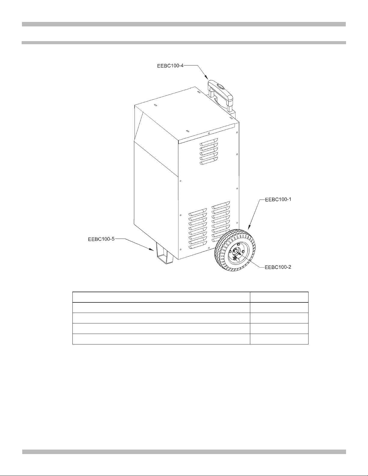
16. REPLACEMENT PARTS LIST – DIAGRAM
Description Stock Number
Replacement Wheel with Snap Ring EEBC100-1
Axle EEBC100-2
Replacement Handle Assembly with Hardware EEBC100-4
Foot with Hardware EEBC100-5

•15 •
EEBC100A-Z
17. WARRANTY
Snap-on Tools Company
Limited Two (2) Year Warranty
Snap-on Tools Company (the “Seller”) warrants only to original purchasers who use the Equipment in their business
that under normal use, care and service, the Equipment (except as otherwise provided herein) shall be free from defects
in material and workmanship for two years from the date of original invoice. Seller does not provide any warranty for
accessories used with the Equipment that are not manufactured by Seller.
SELLER’S OBLIGATIONS UNDER THIS WARRANTY ARE LIMITED SOLELY TO THE REPAIR OR, AT SELLER’S
OPTION, REPLACEMENT OF EQUIPMENT OR PARTS WHICH TO SELLER’S SATISFACTION ARE DETERMINED
TO BE DEFECTIVE AND WHICH ARE NECESSARY, IN SELLER’S JUDGMENT, TO RETURN THIS EQUIPMENT TO
GOOD OPERATING CONDITION. NO OTHER WARRANTIES, EXPRESS OR IMPLIED OR STATUTORY, INCLUDING
WITHOUT LIMITATION ANY IMPLIED WARRANTY OF MERCHANTABILITY OR FITNESS FOR A PARTICULAR
PURPOSE, SHALL APPLY AND ALL SUCH WARRANTIES ARE HEREBY EXPRESSLY DISCLAIMED.
SELLER SHALL NOT BE LIABLE FOR ANY INCIDENTAL, SPECIAL OR CONSEQUENTIAL COSTS OR DAMAGES
INCURRED BY PURCHASERS OR OTHERS (including, without limitations, lost prots, revenues, and anticipated
sales, business opportunities or goodwill, or interruption of business and any other injury or damage).
This Warranty does not cover (and separate charges for parts, labor and related expenses shall apply to) any damage
to, malfunctioning, inoperability or improper operation of the Equipment caused by, resulting from or attributable to
(A) abuse, misuse or tampering; (B) alteration, modication or adjustment of the Equipment by other than Seller’s
authorized representatives; (C) installation, repair or maintenance (other than specied operator maintenance) of
the Equipment or related equipment, attachments, peripherals or optional features by other than Seller’s authorized
representatives; (D) improper or negligent use, application, operation, care, cleaning, storage or handling; (E) re, water,
wind, lightning or other natural causes; (F) adverse environmental conditions, including, without limitation, excessive
heat, moisture, corrosive elements, dust or other air contaminants, radio frequency interference, electric power failure,
power line voltages beyond those specied for the Equipment, unusual physical, electrical or electromagnetic stress
and/or any other condition outside of Seller’s environmental specications; (G) use of the Equipment in combination or
connection with other equipment, attachments, supplies or consumables not manufactured or supplied by Seller; or (H)
failure to comply with any applicable federal, state or local regulation, requirement or specication governing emission
analyzers and related supplies or consumables.
Repairs or replacements qualifying under this Warranty will be performed on regular business days during Seller’s
normal working hours within a reasonable time following purchaser’s request. All requests for Warranty service must be
made during the stated Warranty period. Proof of purchase date is required to make a Warranty request. This Warranty
is nontransferable.
©2019 Snap-on Incorporated.
Snap-on®and BluePoint®are registered trademarks of Snap-on Incorporated.
All Rights Reserved.
Snap-on, 2801 80th St., Kenosha, WI 53143
www.snapon.com
For service, please contact your Snap-on Repair Center.

•16 •
EEBC100A-Z
CARGADOR DE BATERÍAS AUTOMÁTICO
EEBC100A
Voltaje: 6, 12
Amperaje: 6<>2, 40, 200

•17 •
EEBC100A-Z
INTRODUCCIÓN
Gracias por comprar su nuevo Cargador de baterías de
Blue-Point.
El EEBC100A es un cargador avanzado de baterías muy
completo, automático y provisto de ruedas.
Carga baterías de 6 y 12 voltios.
Características:
• Ruedas de 6 pulgadas de diámetro – permiten el
fácil desplazamiento por los talleres y lugares de
estacionamiento.
• Manija retráctil – para fácil almacenamiento
• Arranque de motor de 200 amperes 12 voltios –
para arranques de emergencia
• 40 amperes impulsar, 6<>2 amperes cargador/
mantenedor
• Selector de funciones /
Interruptor ENCENDIDO / APAGADO
• Pantalla digital y botones de control
• Pinzas Sure-Grip de 300 amperios – para polos de
batería superiores y laterales

• 18 •
EEBC100A-Z
Lea todas las instrucciones
Lea, comprenda y siga todos los mensajes de seguridad
y las instrucciones de este manual. Los mensajes
de seguridad incluidos en esta sección del manual
contienen un término indicativo junto a un mensaje de
tres partes y, en algunos casos, un icono.
El término indicativo informa el nivel de peligro de la
situación descrita.
Indica una situación peligrosa inminente que, de no
evitarse, provocará lesiones graves o la muerte del
operador o a personas próximas al área de trabajo.
Indica una situación potencialmente peligrosa que,
de no evitarse, puede causar lesiones graves o la
muerte al operador o a personas próximas al área
de trabajo.
Indica una situación potencialmente peligrosa que,
de no evitarse, podría provocar lesiones moderadas
o menores al operador o a personas próximas al área
de trabajo.
IMPORTANTE
Indica una situación que, de no evitarse, podría
provocar daños en el equipo de prueba o el vehículo.
CONSERVE ESTAS INSTRUCCIONES
Aviso de seguridad
Para su seguridad, le recomendamos leer este manual
atentamente antes de operar su cargador. El cargador
está previsto para ser utilizado por técnicos automotrices
profesionales y adecuadamente capacitados. Los mensajes
de seguridad detallados a continuación y en todo este
manual del usuario cumplen la función de instar al operador
a tener cuidado al utilizar este cargador.
Existen muchas variantes en cuanto a procedimientos,
técnicas, herramientas y piezas en el mantenimiento de
vehículos, así como también en la habilidad de las personas
que realizan los trabajos. Debido a la gran cantidad de
aplicaciones y variantes de productos que pueden probarse
con este equipo, es imposible para Snap-on anticiparse o
brindar recomendaciones o mensajes de seguridad para
cubrir todas las situaciones que podrían presentarse. Queda
bajo responsabilidad del técnico automotriz el conocer en
detalle el sistema a cargar. Es esencial emplear métodos y
procedimientos de mantenimiento adecuados y realizar la
carga de manera apropiada y correcta para evitar poner en
peligro su seguridad, la seguridad de otras personas que
se encuentren en el área de trabajo, el vehículo o el equipo
a cargar.
Se considera que el operador comprende en detalle los
sistemas de batería, carga y arranque de vehículos antes de
comenzar a utilizar el cargador. Es necesario comprender
los principios y las teorías operativas para el uso seguro y
preciso de este cargador.
Previo al uso de este cargador y en todo momento, consulte
y siga los mensajes de seguridad y los procedimientos de
prueba aplicables provistos por el fabricante del vehículo o
equipo a cargar.
Para uso en interiores.

•19 •
EEBC100A-Z
1. INSTRUCCIONES IMPORTANTES DE SEGURIDAD
IMPORTANTE: LEA Y CONSERVE ESTE MANUAL DE INSTRUCCIONES Y SEGURIDAD.
1.1 CONSERVE ESTAS INSTRUCCIONES –
Este manual contiene instrucciones de seguridad
y operación importantes del cargador de baterías
modelo EEBC100A.
RIESGO DE DESCARGA ELÉCTRICA O FUEGO.
1.2 Este cargador no está destinado para ser usado por niños.
1.3 No exponga el cargador a la lluvia o a la nieve.
1.4 El uso de un accesorio no recomendado o suministrado
por el fabricante del cargador de baterías puede
provocar riesgo de incendio, descarga eléctrica o
lesiones a personas.
1.5 Para reducir el riesgo de daños al enchufe o cable
eléctrico, jale del enchufe en lugar de jalar del cable al
desconectar el cargador.
1.6 No se debe utilizar un alargador a menos que resulte
absolutamente necesario. El uso de un alargador
inadecuado puede provocar riesgo de incendio o
descarga eléctrica. En caso de que deba utilizarse un
alargador, asegúrese de que:
• Los pasadores en el enchufe del alargador posean
el mismo número, tamaño y forma que aquellos
presentes en el enchufe del cargador.
• El alargador se encuentre correctamente conectado y
en buenas condiciones eléctricas
• El tamaño del cable sea lo sucientemente extenso
para el amperaje en CA del cargador como se
especica en la sección 8.
1.7 No utilice el cargador si el mismo posee un enchufe
o cable dañado; substituya el cable o el enchufe
inmediatamente por una persona calicada en el ramo.
1.8 No utilice el cargador si el mismo recibió un golpe
fuerte, si se cayó o si sufrió daños de cualquier otra
forma; hágalo revisar por una persona capacitada que
efectúe reparaciones.
1.9 No desarme el cargador; hágalo revisar por una
persona capacitada que efectúe reparaciones cuando
necesite servicio de mantenimiento o una reparación.
Volver a ensamblar el cargador en forma incorrecta
puede provocar riesgo de incendio o descarga eléctrica.
1.10 Para reducir el riesgo de descarga eléctrica, desenchufe
el cargador del tomacorriente antes de intentar llevar a
cabo cualquier actividad de mantenimiento o limpieza. El
simple apagado de los controles no reducirá este riesgo.
1.11 RIESGO DE GASES EXPLOSIVOS.
a. RESULTA PELIGROSO TRABAJAR EN FORMA
CERCANA A UNA BATERÍA DE PLOMO. LAS
BATERÍAS GENERAN GASES EXPLOSIVOS
DURANTE SU NORMAL FUNCIONAMIENTO. POR
ESTE MOTIVO, RESULTA DE SUMA IMPORTANCIA
QUE SIGA LAS INSTRUCCIONES CADA VEZ QUE
UTILIZA EL CARGADOR.
b. Para reducir el riesgo de explosión de una batería,
siga estas instrucciones y aquellas publicadas por
el fabricante de la batería y por el fabricante de
cualquier equipo que intente utilizar en la proximidad
de la batería. Revise las pautas de precaución en
estos productos y en el motor.
2. PRECAUCIONES DE SEGURIDAD PERSONAL
RIESGO DE GASES EXPLOSIVOS.
2.1 Considere la idea de que alguna persona se encuentre
cerca suyo para poder ayudarlo cuando trabaje en
forma cercana a una batería de plomo-ácido.
2.2 Cuente con una gran cantidad de agua potable y jabón
a mano en caso de que el ácido de la batería tenga
contacto con su piel, ropa u ojos.
2.3 Utilice protección visual y corporal completa, incluyendo
gafas de seguridad y prendas de protección. Evite tocar
sus ojos mientras trabaje en forma cercana a la batería.
2.4 Si el ácido de la batería tiene contacto con su piel o su
ropa, lave de inmediato el área afectada con agua y
jabón. En caso de que ingrese ácido en un ojo, sumerja
el mismo de inmediato bajo agua potable corriente por
al menos 10 minutos y obtenga atención médica en
forma inmediata.
2.5 NUNCA fume o permita la presencia de chispas o
llamas en la proximidad de una batería o motor.
2.6 Tenga especial cuidado para reducir el riesgo de dejar
caer una herramienta de metal sobre la batería. Esto
podría provocar chispas o un cortocircuito en la batería
o en cualquier otra pieza eléctrica que podría provocar
una explosión.
2.7 No utilice elementos personales de metal tales como
anillos, pulseras, collares y relojes al trabajar con
una batería de plomo-ácido. Una batería de plomo-
ácido puede producir una corriente de cortocircuito lo
sucientemente elevada como para soldar un anillo o
provocar efectos similares sobre el metal, causando
una quemadura de gravedad.

•20 •
EEBC100A-Z
2.8 Utilice este cargador solamente para cargar baterías
de 6V y 12V de tipo plomo-ácido y AGM-recargables.
Este cargador no está destinado a suministrar energía
a sistemas eléctricos de baja tensión más que en
una aplicación de un motor de arranque. No utilice
este cargador de batería para cargar baterías de pila
seca que por lo general se utilizan con artefactos
domésticos. Estas baterías podrían explotar y provocar
lesiones a personas o daño a la propiedad.
2.9 NUNCA cargue una batería congelada.
3. PREPARACIÓN PARA LA CARGA
RIESGO DE ENTRAR EN CONTACTO CON EL ÁCIDO
DE LA BATERÍA. EL ÁCIDO DE LA BATERÍA ES UN
ÁCIDO SULFÚRICO ALTAMENTE CORROSIVO.
3.1 Si resulta necesario extraer la batería del vehículo para
cargarla, siempre retire el terminal con descarga a tierra
en primer lugar. Asegúrese de que todos los accesorios
en el vehículo se encuentren apagados para evitar la
formación de arcos eléctricos.
3.2 Asegúrese de que el área que rodea a la batería se
encuentre bien ventilada mientras se carga la batería.
3.3 Limpie los terminales de la batería antes de cargar
la batería. Durante la limpieza, evite que la corrosión
producida por aire tenga contacto con sus ojos.
3.4 Agregue agua destilada a cada pila hasta que el
ácido de la batería alcance el nivel especicado por
el fabricante de la batería. No provoque derrames. En
lo que concierne a baterías que no cuentan con tapas
extraíbles para pilas, tales como baterías de plomo-
ácido reguladas por válvulas (VRLA, por sus siglas
en inglés), siga cuidadosamente las instrucciones de
recarga del fabricante.
3.5 Lea, comprenda y siga todas las instrucciones para el
cargador, la batería, el vehículo y cualquier equipo que
se utilice cerca de la batería y el cargador. Controle
todas las precauciones especícas establecidas por el
fabricante de la batería al realizar la carga, así también
como los índices de carga recomendados.
3.6 Determine la tensión de la batería al consultar el manual
del usuario del vehículo y asegúrese de que coincide con
las calicaciones de salida del cargador.
4. UBICACIÓN DEL CARGADOR
RIESGO DE EXPLOSIÓN Y DE ENTRAR EN
CONTACTO CON EL ÁCIDO DE LA BATERÍA.
4.1 Ubique el cargador a la mayor distancia posible de la
batería como lo permitan los cables de CC.
4.2 Nunca ubique el cargador directamente por encima
de la batería que se carga; los gases de la batería
corroerán y dañarán el cargador.
4.3 Nunca permita que el ácido de la batería gotee sobre
el cargador al leer el peso especíco del electrolito o al
cargar la batería.
4.4 No utilice el cargador en un área cerrada o restrinja la
ventilación en cualquier forma.
4.5 No ubique la batería encima del cargador.
5. PRECAUCIONES DE CONEXIÓN EN CC
5.1 Conecte y desconecte las pinzas de salida CC. sólo
después de haber establecido todos los interruptores
del cargador a la posición de “apagado” (si es aplicable)
y de haber desconectado el enchufe de C.A. del
tomacorriente eléctrico. Nunca permita que las pinzas
tengan contacto entre sí. Las pinzas pueden estar
energizadas y pueden producir chispas.
5.2 Sujete las pinzas a la batería y al chasis, como se
indica en en las secciones 6 y 7.
Table of contents
Languages:


